Page 50 of 2490
Date of
Manufacture
T
h
e date of manufacture (Build Date) of a vehicle is define
d as the calendar month and year in which the bodyshell and
powertrain are combined and the completed vehicle leaves the production line. For certain markets, VIN labels carry the
month and year of manufacture. For other markets, the vehicle Build Date is also displayed on a metal plate located at the
top of the battery tray in the trunk.
ANTI-T
HEFT LABELS
F
or
some markets, anti-theft labels bearing the VIN printed on
a special anti-forgery background are positioned on certain
body components. An additional anti-theft label is positioned on the LH side of the engine/automatic transmission casing.
Anti-theft labels must not be removed from a vehicle unless necessitated by component renewal.
ItemDe scrip
tion
1Gross Vehic
l
e Weight
2Gross Trai
n W
eight
3Maxim
u
m Permitted Front Axle Loading
4Maxim
u
m Permitted Rear Axle Loading
Page 273 of 2490

The
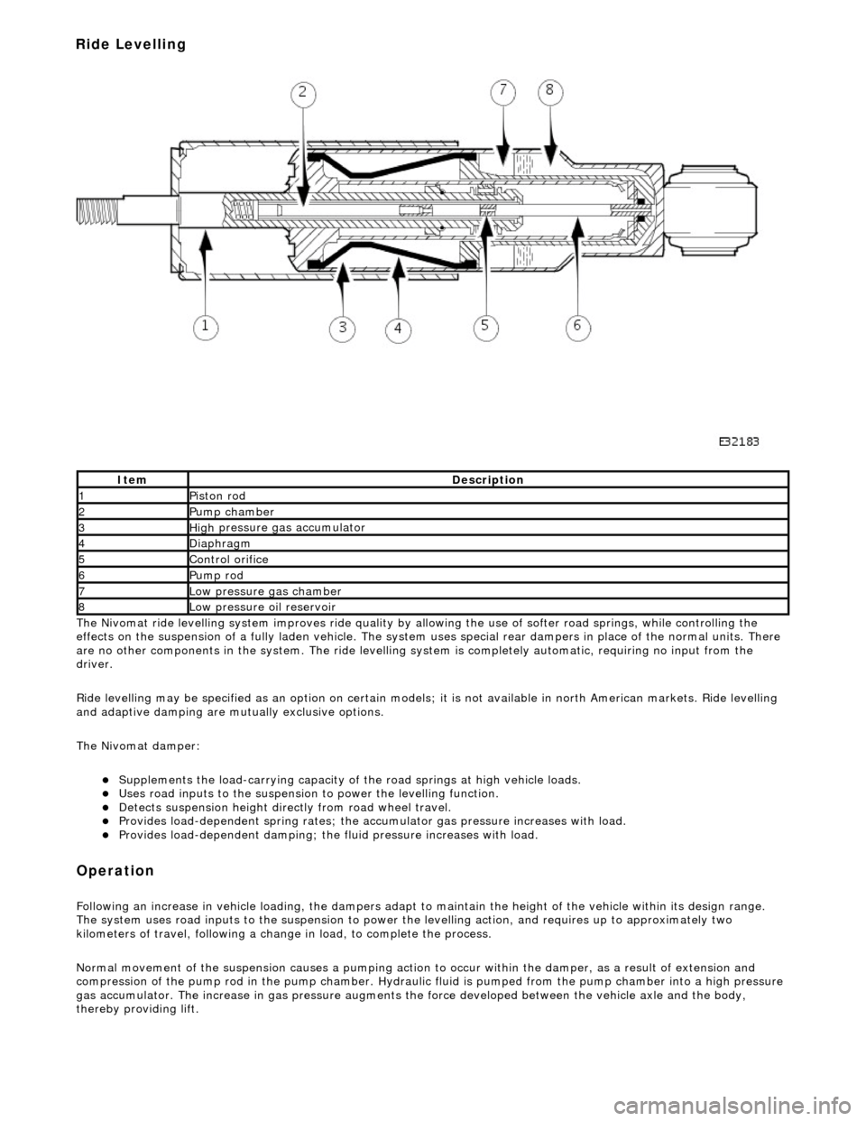
Nivomat ride levelling system improves ride quality by al
lowing the use of softer road springs, while controlling the
effects on the suspension of a fully laden vehicle. The system uses special rear dampers in place of the normal units. There
are no other components in th e system. The ride levelling system is comple tely automatic, requiring no input from the
driver.
Ride levelling may be specified as an opti on on certain models; it is not available in north American markets. Ride levelling
and adaptive damping are mu tually exclusive options.
The Nivomat damper:
Su
pplements the load-carrying capacity of th
e road springs at high vehicle loads.
Uses road inputs to the
suspension to power the levelling function.
De
tects suspension height dire
ctly from road wheel travel.
Provi
des load-dependent spring rates; the ac
cumulator gas pressure increases with load.
Pr
ovides load-dependent damping; the fluid pressure increases with load.
Op
eration
F
ollowing an increase in vehicle loading,
the dampers adapt to maintain the height of the vehicle within its design range.
The system uses road inputs to the suspension to power the levelling action, and requires up to approximately two
kilometers of travel, following a change in load, to complete the process.
Normal movement of the suspension caus es a pumping action to occur within the damper, as a result of extension and
compression of the pump rod in the pump chamber. Hydraulic fluid is pumped from the pump cham ber into a high pressure
gas accumulator. The increase in gas pressure augments the force developed between th e vehicle axle and the body,
thereby providing lift.
It
em
De
scription
1Pi
ston rod
2Pum
p chamber
3High
pressure
gas accumulator
4Diaphragm
5Co
ntrol orifice
6Pump rod
7Low pressure gas ch
amber
8Low pressure oil
reservoir
Ride Levelling
Page 274 of 2490

A c
ontrol orifice in the pump rod determines the levelling height. When the damper is compressed, this orifice is covered.
When the damper extends, the control orif ice is uncovered, pressure is released to the low pressure oil reservoir and the
system ceases to rise. When the vehicle is high after unloading, the opened control or ifice allows fluid to be returned to the
low pressure oil reservoir, and the suspensi on returns to its normal unladen height.
Ad
aptive Damping
•
NOTE: Items 2 and 5 are ALWAYS located
on the passenger side of the vehicle
Adaptive damping enhances vehicle handli ng by the use of special dampers which are controlled by a dedicated control
module.
Adaptive damping may be specified as an option on certai n models. Adaptive damping and ride levelling are mutually
exclusive options. The adaptive damping system is completely automatic, requiring no input from the driver.
A d
aptive Dampers
The adaptiv
e dampers:
Are inst
alled in place of the normal dampers.
Can be identified
by the cable and connector at the top of the unit.
Have two settings; fi
rm and so
ft.
It
e
m
De
scr
iption
1Dam
p
er, front right-hand
2Accel
e
rometer, lateral
3Accel
e
rometer,
front vertical
4D
a
mper, rear right-hand
5Adaptive dampin
g control module (A
DCM)
6Accel
e
rometer, rear vertical
7D
amper, rear l
eft-hand
8Dam
p
er, front left-hand
Page 297 of 2490
I
nstallation
10
.
Clean the seal counterbore.
1. Installation is the re verse of the removal procedure, noting the
following;
2. Lightly lubricate the seal O/D.
3. Chec
k for the correct assembly condition.
E
nsure that the seal, Ryton
ring and backing are aligned
and in contact with each other.
4. NOTE: Correct pinion seal location is automatic.
`Pull' the pinion flan ge / seal assembly down with the pinion
nut - do not hammer the flange.
5. R
efer to the illustration.
R
otate the pinion prior to final tightening.
St
ake the nut to the pinion.
6. Check the pinion drive flange axial run-out.
0,
08 mm MAX TIR.
If t
his specification is exceeded, renew the flange / seal
assembly.
Page 507 of 2490

The driver air bag is moun
ted below the horn operat
ing pad area, adjacent to the steering wheel hub.
For air bag safety and service information, refer to Section 501
-20A Safety Belt
System
Sectio
n
501
-2
0B Supplemental
Re
straint System
.
Upper Steering Column
Motorized Upper Colu
mn Assembly
The motorized upper steering column:
Is adjustable for both til
t and reach.
Has a col
umn adjustment switch installed on
the left-hand side of the lower cowl.
W
ill automatically move to the uppermost tilt and innermost reach position, when the automatic driver entry and exit
function is selected.
Has an instrument li
ghti
ng dimmer switch installed on the left-hand side of the lower cowl.
The steering column adjustment switch:
Controls steeri
ng column reach by
movement of the switch towards an d away from the steering wheel.
Controls steeri
ng column tilt by mo
vement of the switch up and down.
Has two
rotary positions, AUTO and OFF, for selecting the
automatic entry and exit steering column tilt function.
It
em
Par
t Number
De
scription
1-Upper
cowl
2-Lower cowl
3-Ste
ering column adjustment switch
4-Di
mmer switch
Page 508 of 2490
The te
lescopic slider provides driver crash
protection by retracting automatically in the event of an accident; it is clamped in
position to a preset torque.
The motorized upper steering column has the following serviceable parts:
Igniti
on switch assembly.
Igni
ti
on key interlock solenoid.
Ti
lt
motor assembly.
Reach motor assembly.
Manu al Upper Column Assembly
Ite
m
Par
t
Number
De
scr
iption
1-L
o
wer mounting bracket
2-Crash tube
3-Harnes
s c
onnector bracket
4-Tilt motor
5-Reach m
otor
6-Upper
moun
ting bracket
7-Ignition switc
h
(hidden)
8-Igni
ti
on key interlock solenoid
9-S
t
eering wheel mounting shaft
It
e
m
Par
t
Number
De
scr
iption
1-Upper
cowl
2-Lower cowl
3-Colu
mn tilt adjustment lever
4-Col
u
mn reach adjustment lever
5-Di
mm
er switch
Motorized Upper Co
lumn Components
Page 509 of 2490

Is adjustable for both til
t and reach.
Has ca
ble operated reach adjustment, using a rack an
d wedge, with approximately 16 latched positions.
Has si
x latched tilt positions steppe
d at approximately 3° intervals.
Has an u
nlatched top tilt position, allowing the column to be
pulled down to engage the first detent without using the
tilt lever.
Has an instrument li
ghti
ng dimmer switch installed on the left-hand side of the lower cowl.
Manual Upper Column Components
The telescopic slider provides driver crash protection by retracting automatically in the event of an accident; it is clamped in
position to a preset torque.
The manual upper steering column has the following serviceable parts:
Igni
tion switch assembly.
Igni
tion key interlock solenoid.
Bowden
cable and lever assembly.
It
em
Par
t Number
De
scription
1-L
ower mounting bracket
2-Crash tube
3-Harnes
s connector bracket
4-Upper
mounting bracket
5-Ignition switc
h (hidden)
6-Igni
tion key interlock solenoid
7-S
teering wheel mounting shaft
The manu
al upper
steering column:
Page 516 of 2490

IGNITION.
All circuits, except the star
ter motor, are activated. The key rema ins in this position when driving.
Position 'III'
START. The starter operates for as long as the key is held in this position, ag ainst spring pressure. If the engine fails to
start, the key must be returned to position 'I' befo re another start is attempted.
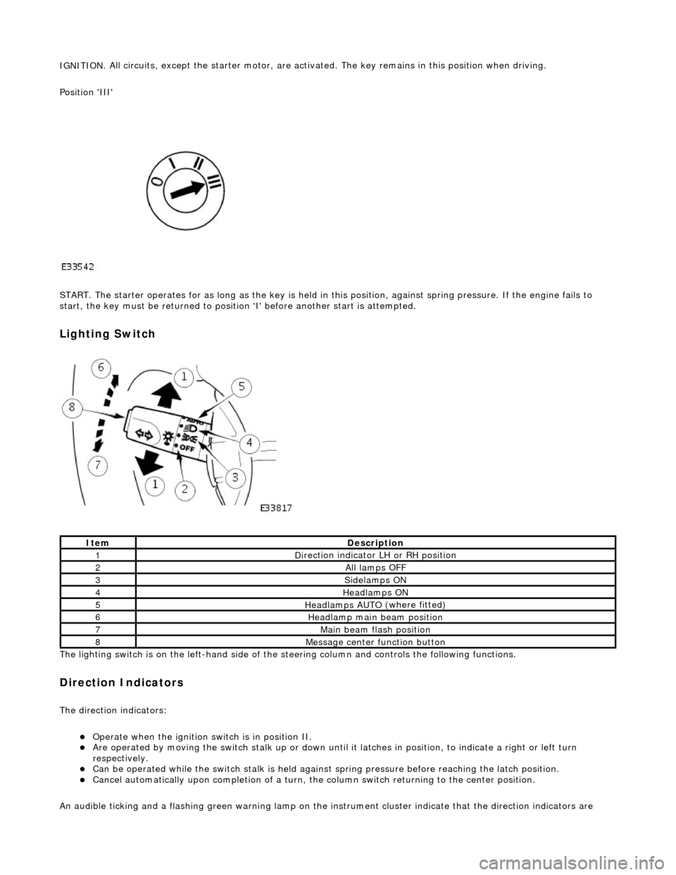
Lighting Switch
The li
ghting switch is on the left-h
and side of the steering column and controls the following functions.
Direction Indicators
The direction in
dicators:
Operate
when the ignition switch is in position II.
Are operat
ed by movi
ng the switch stalk up or down until it latches in position, to in
dicate a right or left turn
respectively.
Can be o p
erated while the switch stalk is held against
spring pressure before reaching the latch position.
Cancel
automatically upon completion of a turn, the
column switch returning to the center position.
An audible ticking and a flashing green warning lamp on the in strument cluster indicate that the direction indicators are
Ite
m
De
scr
iption
1D
i
rection indicator LH or RH position
2All lamps OFF
3Side
lamps ON
4Headlamps ON
5Headlamps AUT O
(where fitted)
6He
adlam
p main beam position
7Mai
n
beam flash position
8M
e
ssage center function button