Page 1111 of 2490

the
intake elbow provide connections for vacuum actuators and are also used to redirect emissions into the engine.
On the right-hand side of the elbow a la rge diameter pipe connects to the brake servo. The smaller pipe provides a vacuum
feed to the fuel rail pressure regulator and throttle cruise control system. On the le ft-hand side of the elbow the front pipe
supplies vacuum control for the evaporative emissions system valves.
Emissions from the engine part load breather (bank 2) and pu rged fuel vapor from the EVAP valve are drawn via a common
T piece into the left-hand side of the intake elbow. Re-cir culated exhaust gas enters the intake elbow via the EGR valve
which is mounted directly on the rear of the elbow : where the EGR system is not used, a blanking plate is fitted.
The fuel system, throttle and emission control system s are described more fully in the relevant sections.
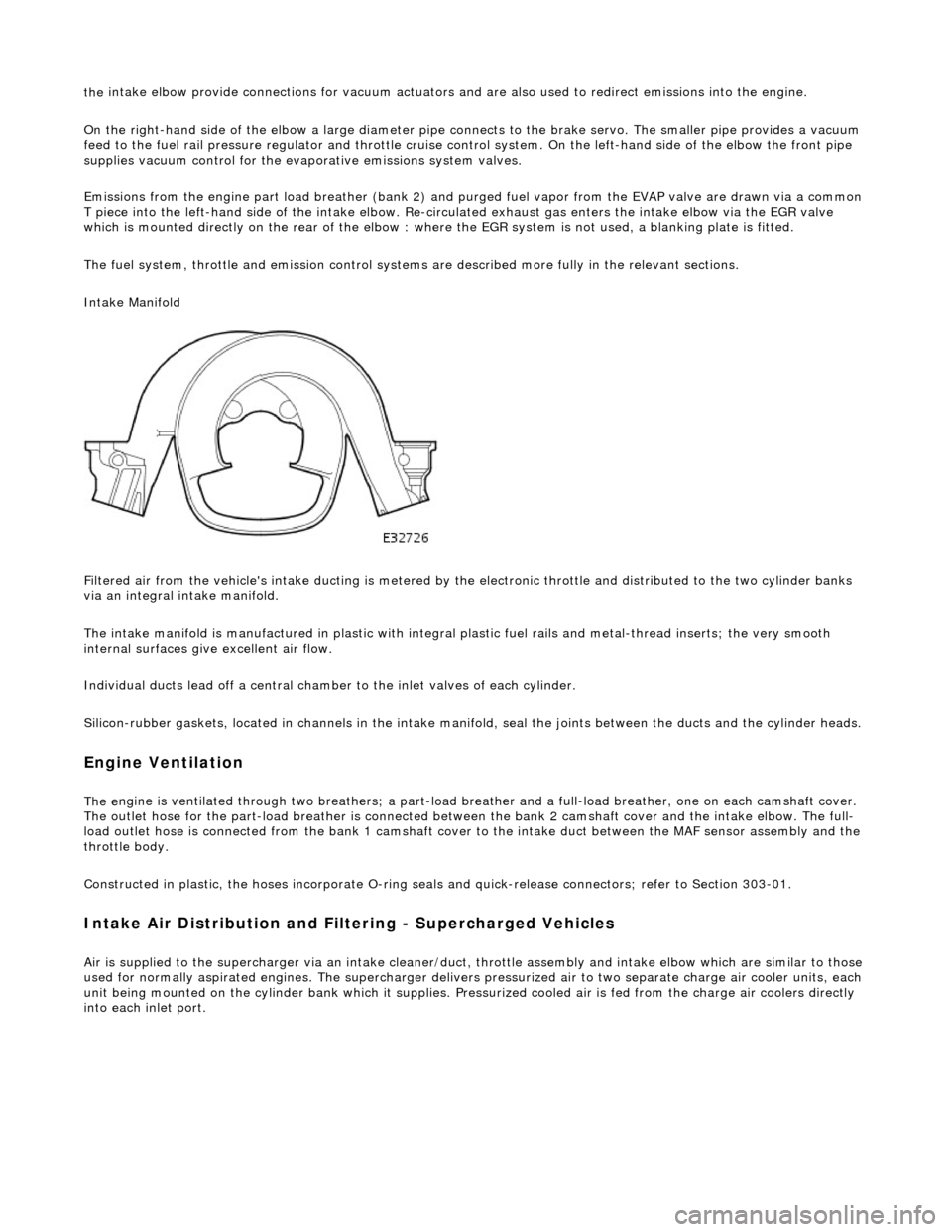
Intake Manifold
Filtered air from the vehicle's intake ducting is metered by th e electronic throttle and distributed to the two cylinder banks
via an integral intake manifold.
The intake manifold is manufactured in plastic with integral plastic fuel rails and metal-thread inserts; the very smooth
internal surfaces give excellent air flow.
Individual ducts lead off a central chamber to the inlet valves of each cylinder.
Silicon-rubber gaskets, loca ted in channels in the intake manifold, seal th e joints between the ducts and the cylinder heads.
Engine Ventilation
The e
ngine is ventilated through two brea
thers; a part-load breather and a full-load breather, one on each camshaft cover.
The outlet hose for the part-load breather is connected between the bank 2 camshaft cover and the intake elbow. The full-
load outlet hose is connected from the bank 1 camshaft cover to the intake duct between the MAF sensor assembly and the
throttle body.
Constructed in plastic, the hoses incorporate O-ring seal s and quick-release connectors; refer to Section 303-01.
I
ntake Air Distribution and Filtering - Supercharged Vehicles
Ai
r is supplied to the supercharger via an
intake cleaner/duct, throttle assembly and intake elbow which are similar to those
used for normally aspirated engines. The su percharger delivers pressurized air to two separate charge air cooler units, each
unit being mounted on the cy linder bank which it supplies. Pr essurized cooled air is fed from the charge air coolers directly
into each inlet port.
Page 1179 of 2490

generates a signal when th
e dr
ive plate passes the sensor
sen
ds the ECM signals indicating crankshaft position and engine speed
is e
ssential for calculating spark timing
En
gine Coolant Temperature (ECT) Sensor
sen
ds the ECM a signal indicating the temperature of the engine coolant
is a t
emperature dependent resistor with a negative temperature coefficient (resistance changes inversely with
respect to temperature) and is constantly monitored by the ECM
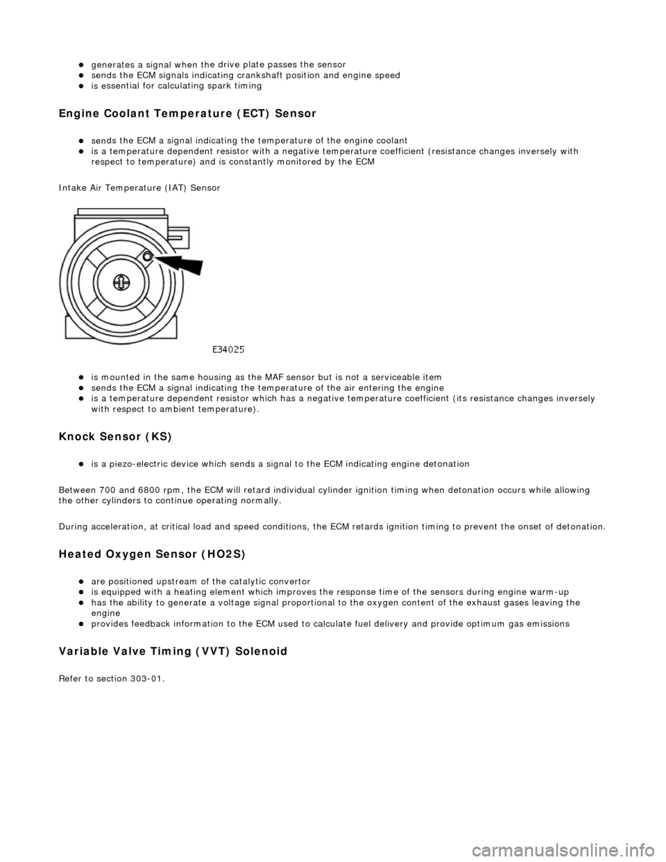
Intake Air Temperature (IAT) Sensor
is m
ounted in the same housing as the MA
F sensor but is not a serviceable item
sen
ds the ECM a signal indicating the temperature of the air entering the engine
is a t
emperature dependent resistor which has a negative
temperature coefficient (its resistance changes inversely
with respect to ambient temperature).
Knock S
ensor (KS)
is a pi
ezo-electric device which sends a signal
to the ECM indicating engine detonation
Between 700 and 6800 rpm, the ECM will retard individual cylinder ignition timing when detonation occurs while allowing
the other cylinders to continue operating normally.
During acceleration, at critical load and speed conditions, the ECM retards ignition timing to prevent the onset of detonation.
H
eated Oxygen Sensor (HO2S)
are
positioned upstream of the catalytic convertor
is equipped with
a heating element wh
ich improves the response time of the sensors during engine warm-up
h
as the ability to generate a voltage signal proportional to the oxygen content of the exhaust gases leaving the
engine
pr
ovides feedback information to the ECM used to calc
ulate fuel delivery and provide optimum gas emissions
Variable V
alve Timing (VVT) Solenoid
R
efer to section 303-01.
Page 1262 of 2490

Contains th
e hydraulic system pump.
Contains
th
e fluid temperature sensor.
The epicyclic geartrain:
Provi des fi
ve forward gears and Reverse.
Has
h
ydraulically actuated, multi-disk clutches, to select the required gear ratios.
Feature
s clutch-to-clutch operation to permit
gear shifts for uninterrupted power flow.
The electro-hydraulic control unit:
Is lo c
ated in the lower part of
the unit, within the fluid pan.
Is controlled
by the TCM (transmissio
n control module), and the manual selector valve which is cable operated.
Re
gulates the flow of fluid to the ge
artrain clutches via three solenoid-operated valv es and the manual selector
valve.
Has fi ve pressure
regulators for controll
ing fluid pressures within the system.
Is con
nected to the TCM via a 16-way connector mounted on
the left-hand side of the transmission casing. Refer to
Connector Pins Identification, Section 307-01A.
The hydraulic system pump:
Is l o
cated at the front of the transmission casing.
Is dri
v
en from the impeller hub,
pressurising the fluid whenever the engine is running.
Supplie
s fluid under pressure to the torq
ue converter, geartrain, electro-hydr aulic control unit and the lubrication
circuit.
D r
aws fluid from the fluid pa
n below the transmission casing, through a filter.
The rear extension housing:
Is bolt
ed to the rear of the transmission casing.
Provides the rear engine / transmi
ssion mo
unting point; refer to section 303-01.
Carrie
s the transmission output shaft oil seal.
Filled-for-l
i
fe Fluid System
The
transm
ission is 'filled for life' and
does not require fluid changes, except where extreme driving conditions prevail.
Routine level checking is not required and a dipstick is not pr ovided. A level / filler plug is fitted for level checking and
replenishment, following service actions; see 303-01 General Procedures.
Transmission Torque Converter