1998 JAGUAR X308 air intake
[x] Cancel search: air intakePage 1147 of 2490
Intake Air Distribution and Filtering - Throt
tle Body Elbow Gasket4.0L SC
V8 - AJ26
Re
moval and Installation
Remov
al
Installation
1.
R
emove throttle intake elbo
w; refer to (SC)19.70.28.
1. Installation is a reversal of the removal procedure.
Page 1148 of 2490
Evaporative E
missions - Evaporative Emissions
Description an
d Operation
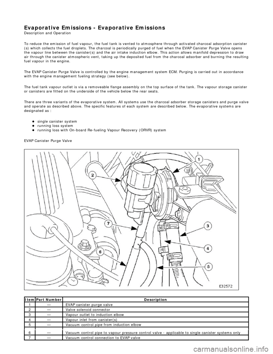
To reduce the emission of fuel vapour, th e fuel tank is vented to atmosphere through activated charcoal adsorption canister
(s) which collects the fuel droplets. The ch arcoal is periodically purged of fuel when the EVAP Canister Purge Valve opens
the vapour line between the canister(s) and the air intake induct ion elbow. This action allows manifold depression to draw
air through the canister atmospheric vent, taking up the deposited fuel from the charcoal adsorber and burning the resulting
fuel vapour in the engine.
The EVAP Canister Purge Valve is controlled by the engine management system ECM. Purging is carried out in accordance
with the engine management fu eling strategy (see below).
The fuel tank vapour outlet is via a removeable flange assemb ly on the top surface of the tank. The vapour storage canister
or canisters are fitted on the underside of the vehicle below the rear seats.
There are three variants of the evaporativ e system. All systems use the charcoal adsorber storage canisters and purge valve
and operate as described above. The specific features of each system are described below. The evaporative systems are
designated as :
sin g
le canister system
ru
nn
ing loss system
ru
nn
ing loss with On-board Re-fueling Vapour Recovery (ORVR) system
EVAP Canister Purge Valve
Ite
m
Par
t
Number
De
scr
iption
1—EVAP canister purge v
alve
2—Valve s
olenoid connector
3—Vapour outlet to indu
ction elbow
4—Vapour
inlet from canister(s)
5—Vacuum contro
l pi
pe from induction elbow
6—Vacuum contro
l pi
pe to vapour pressure control va
lve - applicable to single canister systems only
7—Vacuum
control connection to EVAP valve
Page 1150 of 2490
Thi s
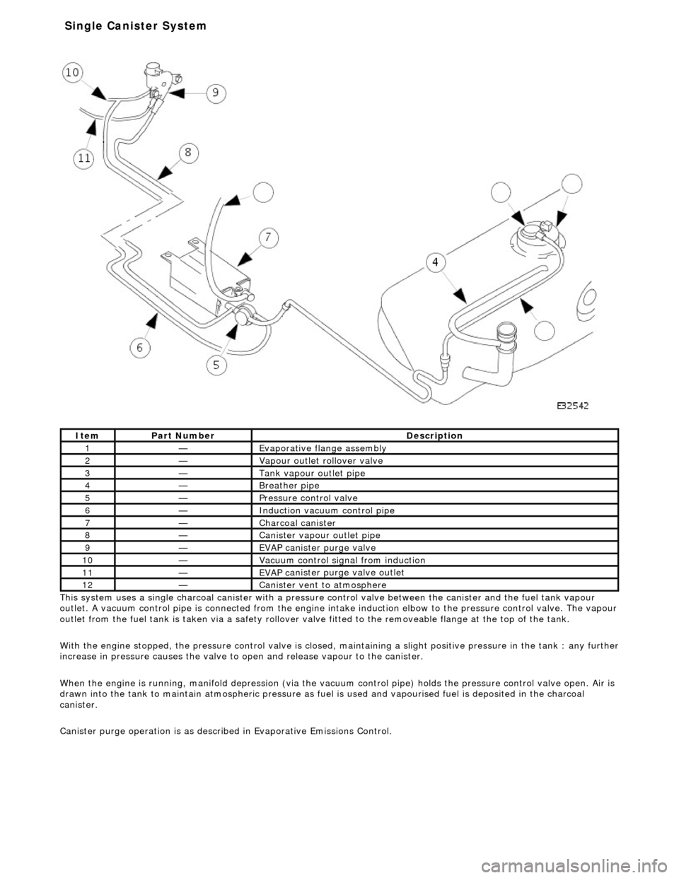
system uses a single charcoal canister with a pressure
control valve between the canister and the fuel tank vapour
outlet. A vacuum control pipe is connecte d from the engine intake induction elbow to the pressure control valve. The vapour
outlet from the fuel tank is taken via a safety rollover valve fitted to the re moveable flange at the top of the tank.
With the engine stopped, the pressure control valve is closed, maintaining a slight positive pre ssure in the tank : any further
increase in pressure causes the valve to open and release vapour to the canister.
When the engine is running, manifold depr ession (via the vacuum control pipe) holds the pressure control valve open. Air is
drawn into the tank to maintain atmospheric pressure as fuel is used and vapourised fuel is deposited in the charcoal
canister.
Canister purge operation is as described in Evaporative Emissions Control.
It e
m
Par
t
Number
De
scr
iption
1—Evaporative flan
ge assembly
2—Vapour outlet rol
lover valve
3—Tank vapour outlet pipe
4—Breather
pipe
5—Pressure control valve
6—Induct
ion vacuum control pipe
7—Charcoal can
i
ster
8—Canister vapour outlet pipe
9—EVAP canister purge v
a
lve
10—Vacuu
m
control sign
al from induction
11—EVAP ca
nister purge valve outlet
12—Canist
er vent
to atmosphere
Single Ca
nister System
Page 1177 of 2490
Th
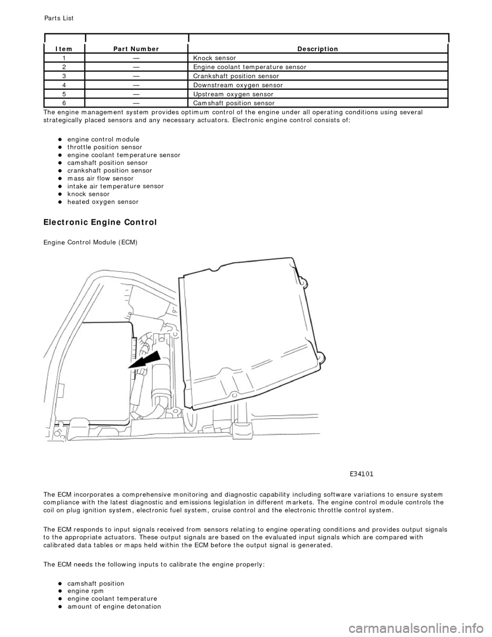
e engine management system provides optimum control of
the engine under all operating conditions using several
strategically placed sensors and any necessary actuators. Electronic engine control consists of:
engine
control module
throttle posi
tion sensor
engi
ne coolant temperature sensor
cam
shaft position sensor
c
rankshaft position sensor
mass air
flow sensor
intake air temper
ature sensor
kn
ock sensor
heat
ed oxygen sensor
Electronic Engine Control
Engine
Control Module (ECM)
The ECM incorporates a comprehensive monitoring and diagnostic capability including software variations to ensure system
compliance with the latest diagnostic and emissions legislation in different markets. The engine control module controls the
coil on plug ignition system, electronic fuel system, cr uise control and the electronic throttle control system.
The ECM responds to input signals received from sensors relating to engine operatin g conditions and provides output signals
to the appropriate actuators. These outp ut signals are based on the evaluated input signals which are compared with
calibrated data tables or maps held within th e ECM before the output signal is generated.
The ECM needs the following inputs to calibrate the engine properly:
cam
shaft position
It
em
Par
t Number
De
scription
1—Knock
sensor
2—Engine
coolant temperature sensor
3—Cranksh
aft position sensor
4—D
ownstream oxygen sensor
5—Upstream oxygen sensor
6—Camshaft position
sensor
P
arts List
engi
ne rpm
engi
ne coolant temperature
amount
of engine detonation
Page 1179 of 2490
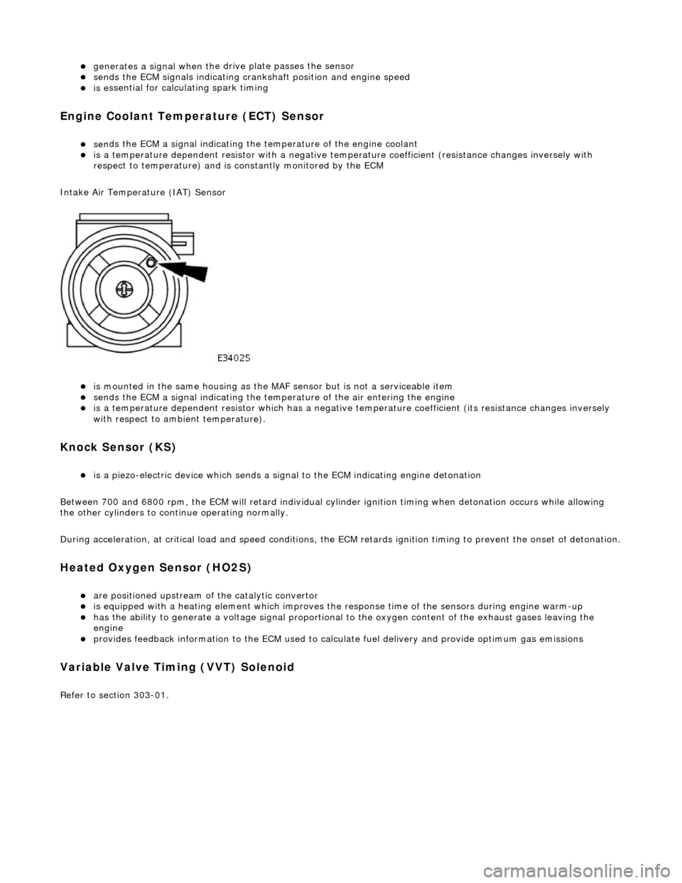
generates a signal when th
e dr
ive plate passes the sensor
sen
ds the ECM signals indicating crankshaft position and engine speed
is e
ssential for calculating spark timing
En
gine Coolant Temperature (ECT) Sensor
sen
ds the ECM a signal indicating the temperature of the engine coolant
is a t
emperature dependent resistor with a negative temperature coefficient (resistance changes inversely with
respect to temperature) and is constantly monitored by the ECM
Intake Air Temperature (IAT) Sensor
is m
ounted in the same housing as the MA
F sensor but is not a serviceable item
sen
ds the ECM a signal indicating the temperature of the air entering the engine
is a t
emperature dependent resistor which has a negative
temperature coefficient (its resistance changes inversely
with respect to ambient temperature).
Knock S
ensor (KS)
is a pi
ezo-electric device which sends a signal
to the ECM indicating engine detonation
Between 700 and 6800 rpm, the ECM will retard individual cylinder ignition timing when detonation occurs while allowing
the other cylinders to continue operating normally.
During acceleration, at critical load and speed conditions, the ECM retards ignition timing to prevent the onset of detonation.
H
eated Oxygen Sensor (HO2S)
are
positioned upstream of the catalytic convertor
is equipped with
a heating element wh
ich improves the response time of the sensors during engine warm-up
h
as the ability to generate a voltage signal proportional to the oxygen content of the exhaust gases leaving the
engine
pr
ovides feedback information to the ECM used to calc
ulate fuel delivery and provide optimum gas emissions
Variable V
alve Timing (VVT) Solenoid
R
efer to section 303-01.
Page 1191 of 2490
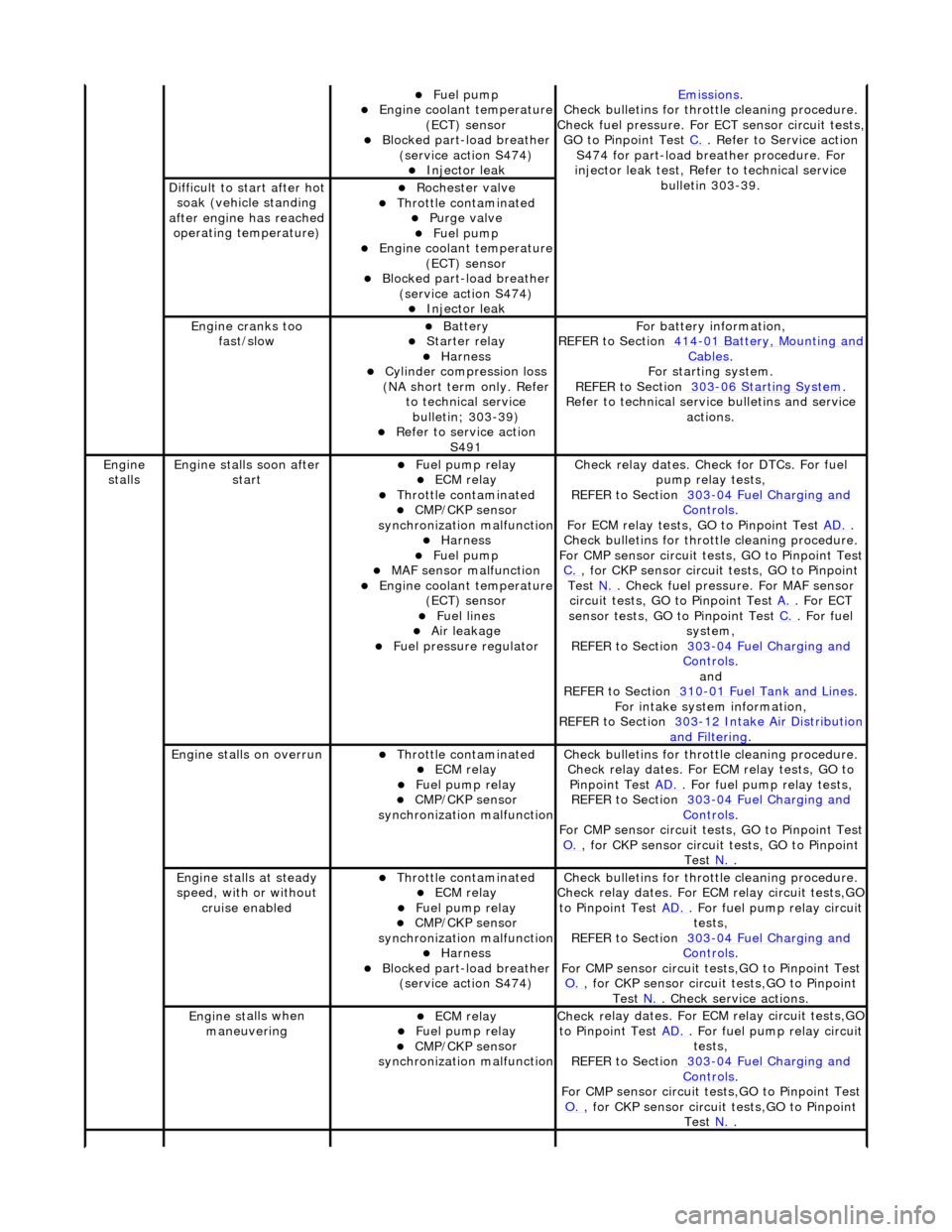
Fue
l pump
Engine coolan
t temperature
(ECT) sensor
Blocked part-load breather (
service action S474)
Injec
tor leak
Emiss
ions
.
Check bull
etins for throttle cleaning procedure.
Check fuel pressure. For ECT sensor circuit tests,
GO to Pinpoint Test C.
. Refer to Servi
ce action
S474 for part-load breather procedure. For
injector leak test, Refer to technical service bulletin 303-39.
D
ifficult to start after hot
soak (vehicle standing
after engine has reached operating temperature)
Roc
hester valve
Thr
ottle contaminated
Purge
valve
Fue
l pump
Engine coolan
t temperature
(ECT) sensor
Blocked part-load breather (
service action S474)
Injec
tor leak
Engine cranks too
fa
st/slow
Batt
ery
Starter relay Harness Cyl
inder compression loss
(NA short term only. Refer to technical service bulletin; 303-39)
R
efer to service action
S491
F
or battery information,
REFER to Section 414
-0
1 Battery, Mounting and
Cables.
F
or starting system.
REFER to Section 303
-06 Sta
rting System
.
R
efer to technical servic
e bulletins and service
actions.
Engine
stalls
Engine st
alls soon after
start
F
uel pump relay
ECM relay Thr
ottle contaminated
CMP/CKP sen
sor
synchronization malfunction
Harness Fue
l pump
MAF
sensor malfunction
Engine coolan
t temperature
(ECT) sensor
Fue
l lines
Air leakage
F
uel pressure regulator
Check r
elay dates. Chec
k for DTCs. For fuel
pump relay tests,
REFER to Section 303
-0
4 Fuel Charging and
Controls.
F
or ECM relay tests, GO to Pinpoint Test
AD.
.
Check bull
etins for throttle cleaning procedure.
For CMP sensor circuit test s, GO to Pinpoint Test
C.
, for
CKP sensor circuit tests, GO to Pinpoint
Test N.
. Check fuel
pressure. For MAF sensor
circuit tests, GO to Pinpoint Test A.
. For EC
T
sensor tests, GO to Pinpoint Test C.
. F
or fuel
system,
REFER to Section 303
-0
4 Fuel Charging and
Controls.
and
REF
ER to Section 310
-0
1 Fuel Tank and Lines
. F
or intake system information,
REFER to Section 303
-1
2 Intake Air Distribution
and F
iltering
.
Engine
stalls on overrun
Thr
ottle contaminated
ECM relay F
uel pump relay
CMP/CKP sen
sor
synchronization malfunction
Check bull
etins for throttle cleaning procedure.
Check relay dates. For ECM relay tests, GO to Pinpoint Test AD.
. F
or fuel pump relay tests,
REFER to Section 303
-0
4 Fuel Charging and
Controls.
F
or CMP sensor circuit test
s, GO to Pinpoint Test
O.
, for
CKP sensor circuit tests, GO to Pinpoint
Test N.
.
E
ngine stalls at steady
speed, with or without cruise enabled
Thr
ottle contaminated
ECM relay F
uel pump relay
CMP/CKP sen
sor
synchronization malfunction
Harness Blocked part-load breather
(
service action S474)
Check bull
etins for throttle cleaning procedure.
Check relay dates. For EC M relay circuit tests,GO
to Pinpoint Test AD.
. F
or fuel pump relay circuit
tests,
REFER to Section 303
-0
4 Fuel Charging and
Controls.
F
or CMP sensor circuit test
s,GO to Pinpoint Test
O.
, for
CKP sensor circuit tests,GO to Pinpoint
Test N.
. Che
ck service actions.
Engine st
alls when
maneuvering
ECM relay F
uel pump relay
CMP/CKP sen
sor
synchronization malfunction
Check r
elay dates. For EC
M relay circuit tests,GO
to Pinpoint Test AD.
. F
or fuel pump relay circuit
tests,
REFER to Section 303
-0
4 Fuel Charging and
Controls.
F
or CMP sensor circuit test
s,GO to Pinpoint Test
O.
, for
CKP sensor circuit tests,GO to Pinpoint
Test N.
.
Page 1192 of 2490
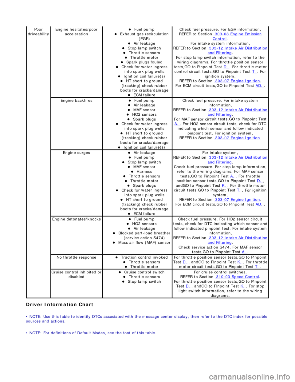
Driver Information
Chart
•
NOTE: Use this table to identify DTCs associated with the me
ssage center display, then refer to the DTC index for possible
sources and actions.
• NOTE: For definitions of Default Modes, see the foot of this table.
Poor
dr iveabilityEngine h e
sitates/poor
acceleration
Fue l
pump
Exhaus
t gas
recirculation
(EGR)
Air leakage Stop lamp swi t
ch
Throttl
e
sensors
Throttl
e
motor
Spark
plugs
fouled
Check f
o
r water ingress
into spark plug wells
Ignition coil fail
ure(s)
HT sh
o
rt to ground
(tracking) check rubber
boots for cracks/damage
ECM failu r
e
Check f
u
el pressure. For EGR information,
REFER to Section 303
-08 En gin
e Emission
Control.
F or i
ntake system information,
REFER to Section 303
-1 2
Intake Air Distribution
and F
ilt
ering
.
F or stop l
amp switch in
formation, refer to the
wiring diagrams. For throttle position sensor
tests,GO to Pinpoint Test D.
. Fo
r throttle motor
control circuit tests,GO to Pinpoint Test T.
. For
igni t
ion system,
REFER to Section 303
-07 En
gine Ignition
.
F or ECM
circuit tests,GO to Pinpoint Test
AD.
.
Engine backfiresFuel
pump
Air leakage MAF se
nsor
HO2 sensors
Spark plugs Check fo
r water ingress
into spark plug wells
HT sh o
rt to ground
(tracking) check rubber
boots for cracks/damage
Ignition coil fail
ure(s)
Chec
k fu
el pressure. For intake system
information,
REFER to Section 303
-12
Intake Air Distribution
and Filt
ering
.
F or MAF sensor ci
rcuit test
s,GO to Pinpoint Test
A.
. F or HO2 sensor
circui
t tests, check for DTC
indicating which sensor and follow indicated pinpoint test. For ignition system,
REFER to Section 303
-07 En
gine Ignition
.
Engine
s
urges
Air leakage
Fuel
pump
Stop lamp swit
ch
MAF s
e
nsor
Harness Throttl
e
sensors
Throttl
e
motor
Spark plugs
Check fo
r water ingress
into spark plug wells
HT sh o
rt to ground
(tracking) check rubber
boots for cracks/damage
ECM failu r
e
Fo
r
intake system,
REFER to Section 303
-1 2
Intake Air Distribution
and Filt
ering
.
Check fu
el pressure. For
stop lamp information,
refer to the wiring diagrams. For MAF sensor tests,GO to Pinpoint Test A.
. Fo
r throttle
position sensor tests,GO to Pinpoint Test D.
,
a n
dGO to Pinpoint Test
K.
. Fo
r throttle motor
circuit tests,GO to Pinpoint Test T.
. For ig
nition
system,
REFER to Section 303
-07 En
gine Ignition
.
F or ECM
circuit tests,GO to Pinpoint Test
AD.
.
Engine detonates/k
nocks
Fue
l
pump
HO2 sensors
Air leakage Blocked part-load breather
(s
ervice action S474)
Mass ai
r fl
ow (MAF) sensor
Chec
k fu
el pressure. Fo
r HO2 sensor circuit
tests, check for DTC indicating which sensor and
follow indicated pinpoint test. For intake system
information,
REFER to Section 303
-1 2
Intake Air Distribution
and Filt
ering
.
Check service action S474
. For MAF sensor
tests,GO to Pinpoint Test A.
.
No t
hrottle response
Traction contr
o
l invoked
Throttl
e
sensors
Throttl
e
motor
Fo
r th
rottle position sensor tests,GO to Pinpoint
Test D.
, andG O to Pinpoint
Test
K.
. Fo
r throttle
motor circuit tests,GO to Pinpoint Test T.
.
Cru i
se control inhibited or
disabled
Cru i
se control switch
Throttle
sensors
Stop lamp swit
ch
For cru
i
se control switches,
REFER to Section 310
-03
Speed Control
.
For th
rottle position sensor tests,GO to Pinpoint
Test D.
, andG O to Pinpoint
Test
K.
. For s t
op
light switch information, refer to the wiring diagrams.
Page 1195 of 2490
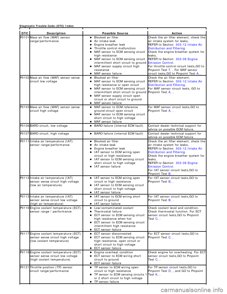
DT
C
De
scription
Possib
le Source
Acti
on
P0101Mass ai
r flow (MAF) sensor
range/performance
Bl
ocked air filter
Air
intake leak
Engine
breather leak
Throttl
e control malfunction
MAF
sensor to ECM sensing circuit
high resistance
MAF
sensor to ECM sensing circuit
intermittent short circuit to ground
MAF
sensor supply circuit high
resistance
MAF
sensor failure
Chec
k the air filter element, check the
air intake system for leaks,
REFER to Section 303
-1
2 Intake Air
Distribu
tion and Filtering
.
Chec
k the engine breather system for
leaks,
REFER to Section 303
-08
Engine
Emissi
on Control
.
F
or throttle control circuit tests,GO to
Pinpoint Test T.
. Fo
r MAF sensor
circuit tests,GO to Pinpoint Test A.
.
P0102Mass ai
r flow (MAF) sensor sense
circuit low voltage
Bl
ocked air filter
MAF
sensor to ECM sensing circuit
high resistance or open circuit
MAF
sensor to ECM sensing circuit
intermittent short circuit to ground
MAF
sensor supply circuit open
circuit or short circuit to ground
MAF
sensor failure
Chec
k the air filter element,
REFER to Section 303
-1
2 Intake Air
Distribu
tion and Filtering
.
For MAF
sensor circuit tests, GO to
Pinpoint Test A.
.
P0103Mass ai
r flow (MAF) sensor sense
circuit high voltage
MAF
sensor to ECM reference
ground circuit open circuit
MAF
sensor to ECM sensing circuit
short circuit to high voltage
MAF sensor
failure
For MAF
sensor circuit tests,GO to
Pinpoint Test A.
.
P0106BARO ci
rcuit, low voltage
BARO f
ailure (internal ECM fault)
Contact deal
er technical support for
advice on possible ECM failure.
P0107BARO ci
rcuit, high voltage
BARO f
ailure (internal ECM fault)
Contact deal
er technical support for
advice on possible ECM failure.
P0111In
take air temperature (IAT)
sensor range/performance
Bl
ocked air filter
Air
intake leak
Engine
breather leak
IAT sensor to
ECM wiring open
circuit or high resistance
IAT se
nsor to ECM sensing circuit
short circuit to high voltage
IAT sensor fail
ure
Chec
k the air filter element, check the
air intake system for leaks,
REFER to Section 303
-1
2 Intake Air
Distribu
tion and Filtering
.
Chec
k the engine breather system for
leaks,
REFER to Section 303
-08
Engine
Emissi
on Control
.
F
or IAT sensor circuit tests,GO to
Pinpoint Test B.
.
P0112In
take air temperature (IAT)
sensor sense circuit high voltage
(low air temperature)
IAT sensor to
ECM wiring open
circuit or high resistance
IAT se
nsor to ECM sensing circuit
short circuit to high voltage
IAT sensor fail
ure
F
or IAT sensor circuit tests,GO to
Pinpoint Test B.
.
P0113In
take air temperature (IAT)
sensor sense circuit low voltage
(high air temperature)
IAT sensor to
ECM wiring short
circuit to ground
IAT sensor fail
ure
F
or IAT sensor circuit tests,GO to
Pinpoint Test B.
.
P0116E
ngine coolant temperature (ECT)
sensor range / performance
Low/contaminated coolant Therm
ostat failure
ECT se
nsor to ECM sensing circuit
high resistance when hot
ECT se
nsor to ECM sensing circuit
intermittent high resistance
ECT sensor
failure
Che
ck coolant level and condition.
Check thermostat function. For ECT
sensor circuit tests,GO to Pinpoint
Test C.
.
P0117E
ngine coolant temperature (ECT)
sensor sense circuit high voltage
(low coolant temperature)
ECT se
nsor disconnected
ECT se
nsor to ECM sensing circuit
high resistance, open circuit or
short circuit to high voltage
ECT sensor
failure
F
or ECT sensor circuit tests,GO to
Pinpoint Test C.
.
P0118E
ngine coolant temperature (ECT)
sensor sense circuit low voltage
(high coolant temperature)
Engine
overheat condition
ECT se
nsor to ECM wiring short
circuit to ground
ECT sensor
failure
Chec
k engine for overheating. For ECT
sensor circuit tests,GO to Pinpoint
Test C.
.
P0121Thro
ttle position (TP) sensor
circuit rang e/performance
TP sensor
to ECM wiring open
circuit or high resistance
TP se
nsor to ECM sensing circuits 1
or 2 short circuit to high voltage
TP sensor
failure
F
or TP sensor circ
uit tests,GO to
Pinpoint Test D.
, and G
O to Pinpoint
Test K.
.
D
iagnostic Trouble Code (DTC) Index