1998 JAGUAR X308 air intake
[x] Cancel search: air intakePage 1197 of 2490
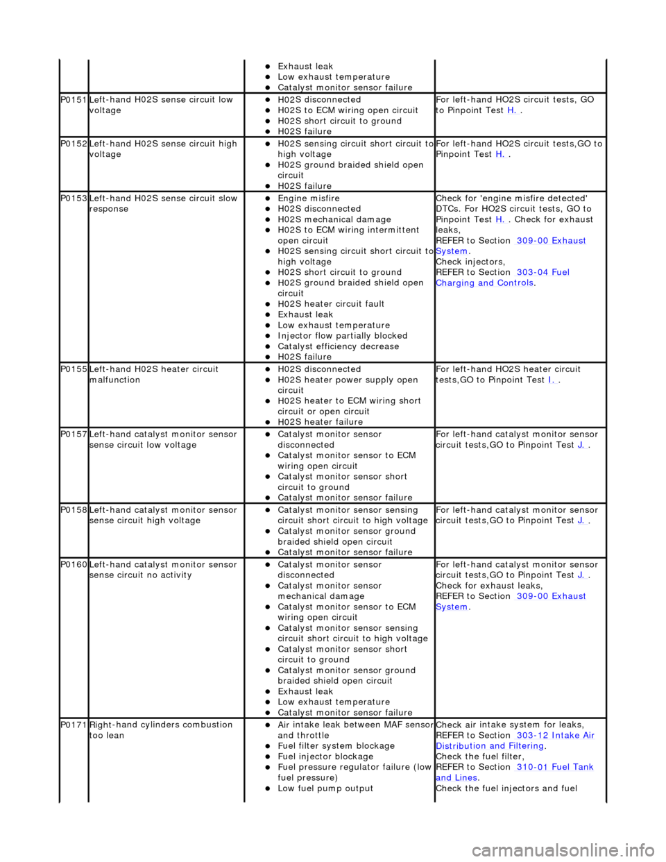
Exhaus
t leak
Low e
xhaust temperature
Cat
alyst monitor sensor failure
P0151Le
ft-hand H02S sense circuit low
voltage
H02
S disconnected
H0
2S to ECM wiring open circuit
H0
2S short circuit to ground
H0
2S failure
F
or left-hand HO2S circuit tests, GO
to Pinpoint Test H.
.
P0152Le
ft-hand H02S sense circuit high
voltage
H02
S sensing circuit short circuit to
high voltage
H0
2S ground braided shield open
circuit
H0
2S failure
F
or left-hand HO2S circuit tests,GO to
Pinpoint Test H.
.
P0153Le
ft-hand H02S sense circuit slow
response
Engine
misfire
H02
S disconnected
H0
2S mechanical damage
H0
2S to ECM wiring intermittent
open circuit
H02
S sensing circuit short circuit to
high voltage
H0
2S short circuit to ground
H0
2S ground braided shield open
circuit
H0
2S heater circuit fault
Exhaus
t leak
Low e
xhaust temperature
Injector fl
ow partially blocked
Catal
yst efficiency decrease
H0
2S failure
Chec
k for 'engine misfire detected'
DTCs. For HO2S circ uit tests, GO to
Pinpoint Test H.
. Check for exhaust
leak
s,
REFER to Section 309
-00
Exhaust
Sy
stem
.
Chec
k injectors,
REFER to Section 303
-04
Fuel
Charging and Con
trols
.
P0155Left-hand H02S heater
circuit
malfunction
H02
S disconnected
H0
2S heater power supply open
circuit
H0
2S heater to ECM wiring short
circuit or open circuit
H0
2S heater failure
F
or left-hand HO2S heater circuit
tests,GO to Pinpoint Test I.
.
P0157Le
ft-hand catalyst monitor sensor
sense circuit low voltage
Catal
yst monitor sensor
disconnected
Catal
yst monitor sensor to ECM
wiring open circuit
Catal
yst monitor sensor short
circuit to ground
Cat
alyst monitor sensor failure
F
or left-hand catalyst monitor sensor
circuit tests,GO to Pinpoint Test J.
.
P0158Le
ft-hand catalyst monitor sensor
sense circuit high voltage
Catal
yst monitor sensor sensing
circuit short circuit to high voltage
Catalyst
monitor sensor ground
braided shield open circuit
Cat
alyst monitor sensor failure
F
or left-hand catalyst monitor sensor
circuit tests,GO to Pinpoint Test J.
.
P0160Le
ft-hand catalyst monitor sensor
sense circuit no activity
Catal
yst monitor sensor
disconnected
Catal
yst monitor sensor
mechanical damage
Catal
yst monitor sensor to ECM
wiring open circuit
Catal
yst monitor sensor sensing
circuit short circuit to high voltage
Catal
yst monitor sensor short
circuit to ground
Catalyst
monitor sensor ground
braided shield open circuit
Exhaus
t leak
Low e
xhaust temperature
Cat
alyst monitor sensor failure
F
or left-hand catalyst monitor sensor
circuit tests,GO to Pinpoint Test J.
.
Check f
or exhaust leaks,
REFER to Section 309
-00
Exhaust
Sy
stem
.
P0171Right
-hand cylinders combustion
too lean
Air
intake leak between MAF senso
r and th
rottle
F
uel filter system blockage
F
uel injector blockage
F
uel pressure regulator failure (low
fuel pressure)
Low f
uel pump output
Check ai
r intake system for leaks,
REFER to Section 303
-1
2 Intake Air
Distribu
tion and Filtering
.
Check the fuel fi
lter,
REFER to Section 310
-01
Fuel Tank
and Lines.
Chec
k the fuel injectors and fuel
Page 1198 of 2490
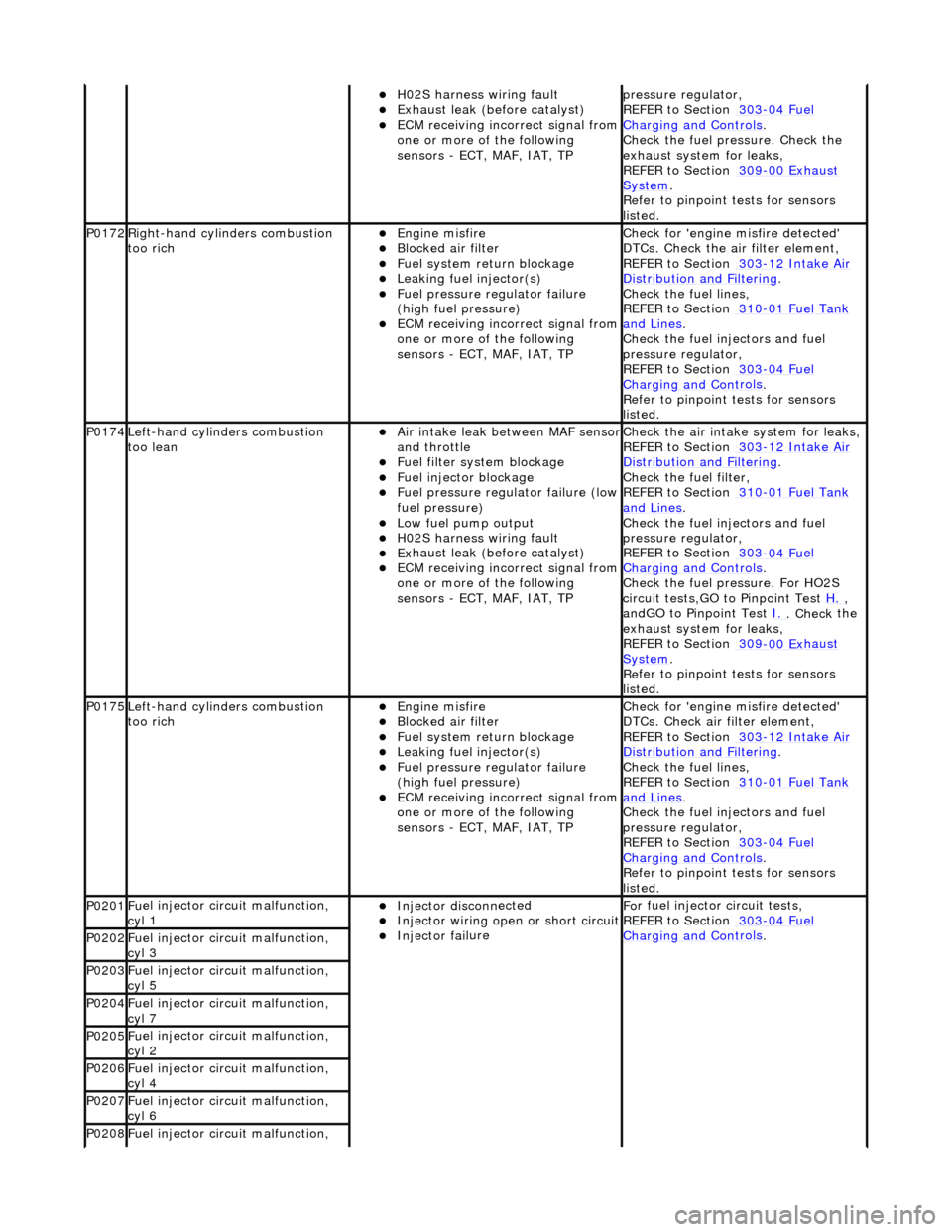
H02S harness wiri
ng fault
E
x
haust leak (before catalyst)
ECM receivi
n
g incorrect signal from
one or more of the following
sensors - ECT, MAF, IAT, TP
pr essure regulator,
REF
ER to Section 303
-04
Fu
el
Charging and Con
t
rols
.
Chec k the
fuel pressure. Check the
exhaust system for leaks,
REFER to Section 309
-00 Ex
haust
Sy
ste
m
.
R e
fer to pinpoint tests for sensors
listed.
P0172Right -
hand cylinders combustion
too rich
Engine m
isfire
Bl
ocked air
filter
F
u
el system return blockage
Leak
i
ng fuel injector(s)
F
u
el pressure regulator failure
(high fuel pressure)
ECM receivi n
g incorrect signal from
one or more of the following
sensors - ECT, MAF, IAT, TP
Chec k for 'en
gine misfire detected'
DTCs. Check the air filter element,
REFER to Section 303
-1 2
Intake Air
Distribu
tion and Filterin
g
.
Chec k the
fuel lines,
REFER to Section 310
-01 Fu
el Tank
and Lines.
Chec k the
fuel injectors and fuel
pressure regulator,
REFER to Section 303
-04 Fu
el
Charging and Con
t
rols
.
R e
fer to pinpoint tests for sensors
listed.
P0174L e
ft-hand cylinders combustion
too lean
Air in
take leak between MAF senso
r and th
ro
ttle
F
u
el filter system blockage
F
u
el injector blockage
F
u
el pressure regulator failure (low
fuel pressure)
Low fu
el pump output
H0
2S harness wiri
ng fault
E
x
haust leak (before catalyst)
ECM receivi
n
g incorrect signal from
one or more of the following
sensors - ECT, MAF, IAT, TP
Check the ai r intak
e system for leaks,
REFER to Section 303
-1 2
Intake Air
Distribu
tion and Filterin
g
.
Check the fuel fi lter,
REF
ER to Section 310
-01
Fu
el Tank
and Lines.
Chec k the
fuel injectors and fuel
pressure regulator,
REFER to Section 303
-04 Fu
el
Charging and Con
t
rols
.
Chec k the
fuel pressure. For HO2S
circuit tests,GO to Pinpoint Test H.
,
a n
dGO to Pinpoint Test
I.
. Check
the
exhaust system for leaks,
REFER to Section 309
-00 Ex
haust
Sy
ste
m
.
R e
fer to pinpoint tests for sensors
listed.
P0175L e
ft-hand cylinders combustion
too rich
Engine m
isfire
Bl
ocked air
filter
F
u
el system return blockage
Leak
i
ng fuel injector(s)
F
u
el pressure regulator failure
(high fuel pressure)
ECM receivi n
g incorrect signal from
one or more of the following
sensors - ECT, MAF, IAT, TP
Chec k for 'en
gine misfire detected'
DTCs. Check air filter element,
REFER to Section 303
-1 2
Intake Air
Distribu
tion and Filterin
g
.
Chec k the
fuel lines,
REFER to Section 310
-01 Fu
el Tank
and Lines.
Chec k the
fuel injectors and fuel
pressure regulator,
REFER to Section 303
-04 Fu
el
Charging and Cont
rols
.
Re
fer to pinpoint tests for sensors
listed.
P0201 Fu
el injector circuit malfunction,
cyl 1
Injector discon n
ected
Inject
or wir
ing open or short circuit
Injector fail
ure
F
o
r fuel injector
circuit tests,
REFER to Section 303
-04 Fu
el
Charging and Con
t
rols
. P0202F
u
el injector circuit malfunction,
cyl 3
P0203F u
el injector circuit malfunction,
cyl 5
P0204F u
el injector circuit malfunction,
cyl 7
P0205F u
el injector circuit malfunction,
cyl 2
P0206F u
el injector circuit malfunction,
cyl 4
P0207F u
el injector circuit malfunction,
cyl 6
P0208F u
el injector circuit malfunction,
Page 1201 of 2490
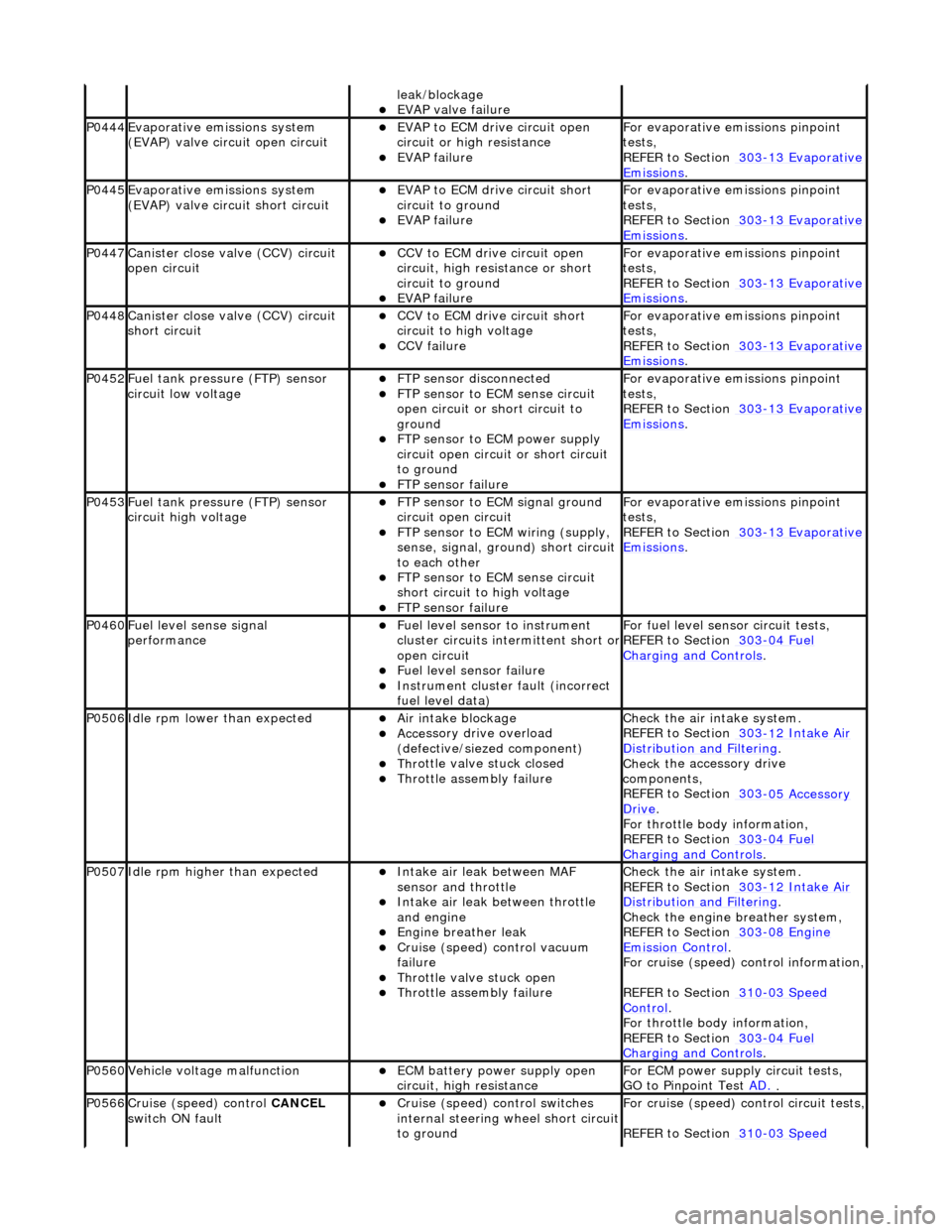
leak
/blockage
EVAP valve failure
P0444Evaporati
ve emissions system
(EVAP) valve circuit open circuit
EVAP t
o ECM drive circuit open
circuit or high resistance
EVAP failu
re
F
or evaporative emissions pinpoint
tests,
REFER to Section 303
-1
3 Evaporative
Emiss
ions
.
P0445Evaporati
ve emissions system
(EVAP) valve circuit short circuit
E
VAP to ECM drive circuit short
circuit to ground
EVAP failu
re
F
or evaporative emissions pinpoint
tests,
REFER to Section 303
-1
3 Evaporative
Emiss
ions
.
P0447Cani
ster close valve (CCV) circuit
open circuit
CCV to ECM
drive circuit open
circuit, high resi stance or short
circuit to ground
EVAP failu
re
F
or evaporative emissions pinpoint
tests,
REFER to Section 303
-1
3 Evaporative
Emiss
ions
.
P0448Cani
ster close valve (CCV) circuit
short circuit
CCV to
ECM drive circuit short
circuit to high voltage
CCV failure
F
or evaporative emissions pinpoint
tests,
REFER to Section 303
-1
3 Evaporative
Emiss
ions
.
P0452F
uel tank pressure (FTP) sensor
circuit low voltage
FTP
sensor disconnected
FTP
sensor to ECM sense circuit
open circuit or short circuit to
ground
FTP sen
sor to ECM power supply
circuit open circuit or short circuit
to ground
F
TP sensor failure
F
or evaporative emissions pinpoint
tests,
REFER to Section 303
-1
3 Evaporative
Emiss
ions
.
P0453F
uel tank pressure (FTP) sensor
circuit high voltage
FTP
sensor to ECM signal ground
circuit open circuit
F
TP sensor to ECM wiring (supply,
sense, signal, ground) short circuit
to each other
FTP
sensor to ECM sense circuit
short circuit to high voltage
F
TP sensor failure
F
or evaporative emissions pinpoint
tests,
REFER to Section 303
-1
3 Evaporative
Emiss
ions
.
P0460Fue
l level sense signal
performance
Fue
l level sensor
to instrument
cluster circuits in termittent short or
open circuit
F
uel level sensor failure
Instrument cluster
faul
t (incorrect
fuel level data)
F
or fuel level sensor
circuit tests,
REFER to Section 303
-04
Fuel
Charging and Con
trols
.
P0506Idl
e rpm lower than expected
Ai
r intake blockage
Acce
ssory drive overload
(defective/siezed component)
Thr
ottle valve stuck closed
Throttl
e assembly failure
Chec
k the air intake system.
REFER to Section 303
-1
2 Intake Air
Distribu
tion and Filtering
.
Check t
he accessory drive
components,
REFER to Section 303
-0
5 Accessory
Dr
ive
.
F
or throttle body information,
REFER to Section 303
-04
Fuel
Charging and Con
trols
.
P0507Idle rpm
higher than expected
Inta
ke air leak between MAF
sensor and throttle
Inta
ke air leak between throttle
and engine
Engine
breather leak
Cruis
e (speed) control vacuum
failure
Thr
ottle valve stuck open
Throttl
e assembly failure
Chec
k the air intake system.
REFER to Section 303
-1
2 Intake Air
Distribu
tion and Filtering
.
Chec
k the engine breather system,
REFER to Section 303
-08
Engine
Emissi
on Control
.
F
or cruise (speed) control information,
REFER to Section 310
-03
Speed
Control.
F
or throttle body information,
REFER to Section 303
-04
Fuel
Charging and Con
trols
.
P0560Vehicle voltage
malfunction
ECM battery
power supply open
circuit, high resistance
F
or ECM power supply circuit tests,
GO to Pinpoint Test AD.
.
P0566Cruise (speed) contr
ol
CANCEL
switch ON fault
Cru
ise (speed) control switches
internal steering wheel short circuit
to ground
For cru
ise (speed) control circuit tests,
REFER to Section 310
-03
Speed
Page 1204 of 2490
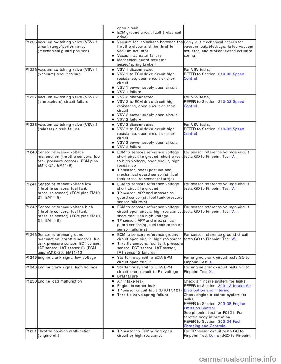
op
en circuit
ECM ground circuit faul
t (relay coil
drive)
P1235Vacuu m
switching valve (VSV) 1
circuit range/ performance
(mechanical guard position)
Vac u
um leak/blockage between the
throttle elbow and the throttle
vacuum actuator
Vacuu m
actuator failure
Mechanica
l
guard actuator
seized/spring broken
Carr y out mechanical checks
for
vacuum leak/blockag e, failed vacuum
actuator, and broken /siezed actuator
spring.
P1236Vacuu m
switching valve (VSV) 1
(vacuum) circuit failure
VSV 1 disconne cted
VSV 1 to ECM drive circu
i
t high
resistance, open circuit or short
circuit
VSV 1 powe r supply open
circuit
VSV 1 failu
r
e
For VSV tests,
REF
ER to Section 310
-03
Sp
eed
Control.
P1237Vacuu
m
switching valve (VSV) 2
(atmosphere) circuit failure
VSV 2 disconne cted
VSV 2 to ECM drive circu
i
t high
resistance, open circuit or short
circuit
VSV 2 power supply open
circuit
VSV 2 failu
r
e
For VSV tests,
REF
ER to Section 310
-03
Sp
eed
Control.
P1238Vacuu
m
switching valve (VSV) 3
(release) circuit failure
VSV 3 disconne cted
VSV 3 to ECM drive circu
i
t high
resistance, open circuit or short
circuit
VSV 3 powe r supply open
circuit
VSV 3 failu
r
e
For VSV tests,
REF
ER to Section 310
-03
Sp
eed
Control.
P1240Sensor r
e
fere
nce voltage
malfunction (throttle sensors, fuel
tank pressure se nsor) (ECM pins
EM10-21; EM11-8)
ECM t o
sensors reference voltage
short circuit to ground, short circuit
to high voltage, op en circuit, high
resistance
TP sensor , pedal position and
mechan
ical guard sensor(s), fuel
tank pressure sens or failure(s)
Fo
r sensor reference voltage circuit
tests,GO to Pinpoint Test V.
.
P1241Sensor re
ferenc
e voltage low
(throttle sensors, fuel tank
pressure sensor) (ECM pins EM10-
21; EM11-8)
ECM t o
sensors reference voltage
short circuit to ground
TP sensor , APP
and mechanical
guard sensor(s), fuel tank pressure
sensor failure(s)
F o
r sensor reference voltage circuit
tests,GO to Pinpoint Test V.
.
P1242Sensor re
ferenc
e voltage high
(throttle sensors, fuel tank
pressure sensor) (ECM pins EM10-
21; EM11-8)
ECM t o
sensors reference voltage
circuit open circuit, high resistance,
short circuit to high voltage
TP sensor , APP
and mechanical
guard sensor(s), fuel tank pressure
sensor failure(s)
F o
r sensor reference voltage circuit
tests,GO to Pinpoint Test V.
.
P1243Sensor re
ference ground
malfunction (throttle sensors, fuel
tank pressure sensor, ECT sensor,
IAT sensor, IAT sensor 2) (ECM
pins EM10-20; EM11-12)
ECM t o
sensors reference ground
circuit open circuit, high resistance
Throttle sensors, fuel
tank pressure
sensor, ECT sensor, IAT sensor,
IAT sensor 2 failures
F o
r sensor reference ground circuit
tests,GO to Pinpoint Test W.
.
P1245Engine crank signal low voltage Starter relay coi
l to ECM/BPM
circuit open circuit
For en gin
e crank circuit tests,GO to
Pinpoint Test X.
.
P1246Engine crank signal high voltage Starter relay coi
l to ECM/BPM
circuit short circuit to B+ voltage
B P
M failure
For en
gin
e crank circuit tests,GO to
Pinpoint Test X.
.
P1250Engine load
malfunction
Air in
take leak
Engine breath
er leak
TP sens
or circuit fault (DTC P0121)
Throttle
valve spring failure
Check air i
ntake system for leaks,
REFER to Section 303
-12
Intake Air
Distribution and Filterin
g
.
Check engi
ne breather system for
leaks,
REFER to Section 303
-08 En
gine
Emissi
on Control.
Se e
pinpoint test for P0121. For
throttle body information,
REFER to Section 303
-04 Fu
el
Charging and Con
t
rols
.
P1251Thr
o
ttle position malfunction
(engine off)
TP sensor to ECM wiri
ng open
circuit or high resistance
F o
r TP sensor circ
uit tests,GO to
Pinpoint Test D.
, andGO to Pinpoint
Page 1208 of 2490
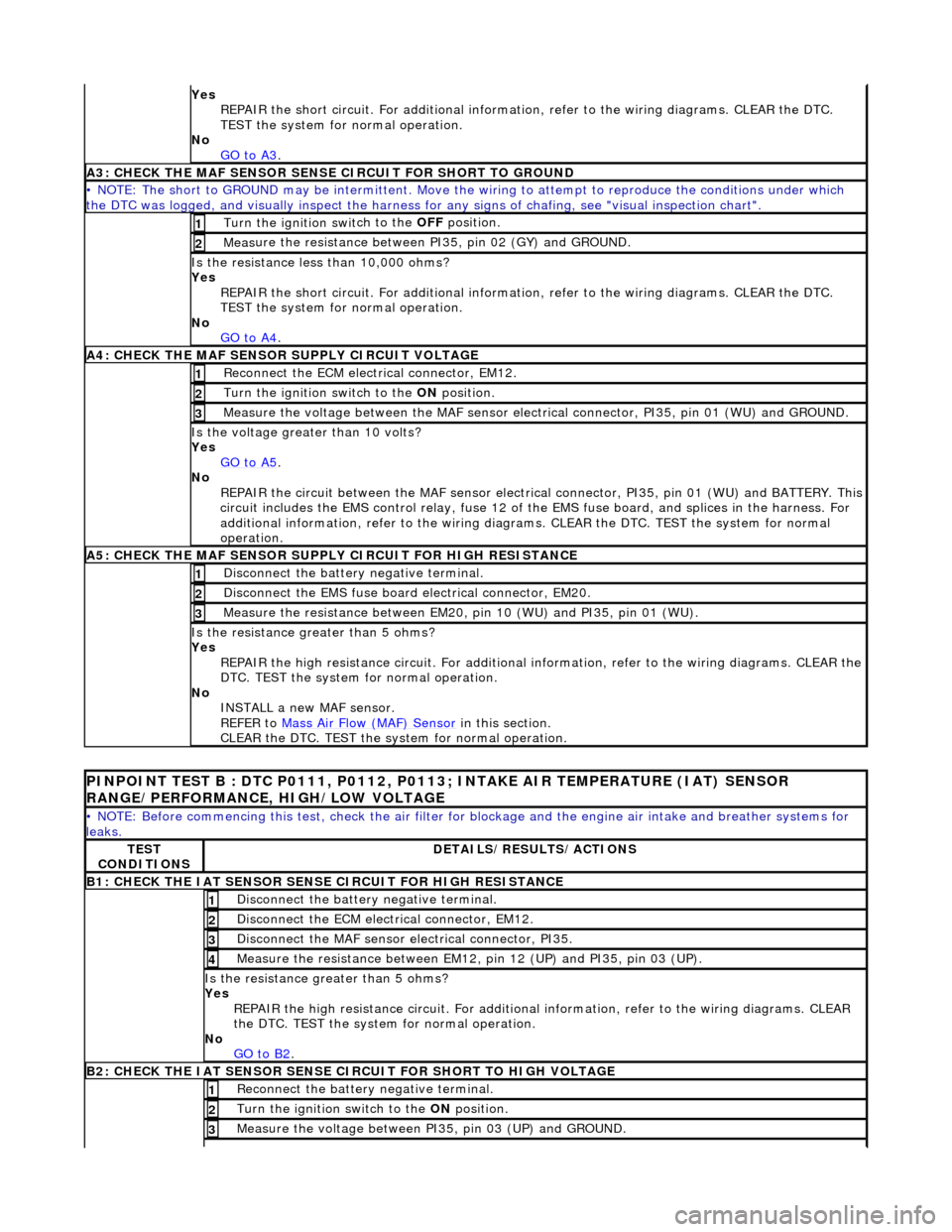
Yes
R
EPAIR the short circuit. For addi
tional information, refer to the wiring diagrams. CLEAR the DTC.
TEST the system for normal operation.
No GO to A3
.
A3: CHECK THE MAF SENSO
R SENS
E CIRCUIT FOR SHORT TO GROUND
• NO
TE: The short to GROUND may be intermittent. Move the
wiring to attempt to reproduce the conditions under which
the DTC was logged, and visually inspect the harness for any signs of chafing, see "visual inspection chart".
Turn the ignition swit
ch to the OFF
position.
1
Measure t
he resistance between PI35, pin 02 (GY) and GROUND.
2
Is t
he resistance less than 10,000 ohms?
Yes REPAIR the short circuit. For addi tional information, refer to the wiring diagrams. CLEAR the DTC.
TEST the system for normal operation.
No GO to A4
.
A4: CHEC K THE MA
F SENSOR SUPPLY CIRCUIT VOLTAGE
Re
conn
ect the ECM electrical connector, EM12.
1
Turn the ignition swi
t
ch to the ON
position.
2
Me
asure the voltage between the MAF sensor electrical connector, PI35, pin 01 (WU) and GROUND.
3
Is the vol
t
age greater than 10 volts?
Yes GO to A5
.
No
REP
AIR the circuit between the MAF sensor electric
al connector, PI35, pin 01 (WU) and BATTERY. This
circuit includes the EMS control rela y, fuse 12 of the EMS fuse board, and splices in the harness. For
additional information, refer to the wiring diagrams. CLEAR the DT C. TEST the system for normal
operation.
A5: CHECK THE MAF SENSO
R SUPPLY CIRCUIT FOR HIGH RESISTANCE
Di
sc
onnect the battery negative terminal.
1
Di
sc
onnect the EMS fuse board electrical connector, EM20.
2
Meas
ure t
he resistance between EM20,
pin 10 (WU) and PI35, pin 01 (WU).
3
Is the res
istance greater than 5 ohms?
Yes REPAIR the high resistance circuit. For additional information, refer to the wiring diagrams. CLEAR the
DTC. TEST the system for normal operation.
No INSTALL a new MAF sensor.
REFER to Mass Air Flow (MAF) Sensor
in this
section.
CLEAR the DTC. TEST the system for normal operation.
P INPOINT TES
T B : DTC P0111, P0112, P0113;
INTAKE AIR TEMPERATURE (IAT) SENSOR
RANGE/PERFORMANCE, HIGH/LOW VOLTAGE
•
NOTE: Before commencing this
test, check the air filter for blockage and the engine air intake and breather systems for
leaks.
TE S
T
CONDITIONS
D E
TAILS/RESULTS/ACTIONS
B1: CHECK
THE IAT SENSOR
SENS
E CIRCUIT FOR HIGH RESISTANCE
Disc
onnect the battery negative terminal.
1
D
i
sconnect the ECM electrical connector, EM12.
2
Di
sc
onnect the MAF sensor electrical connector, PI35.
3
Me
asure
the resistance between EM12, pin 12 (UP) and PI35, pin 03 (UP).
4
Is th
e res
istance greater than 5 ohms?
Yes REPAIR the high resistance circui t. For additional information, refer to the wiring diagrams. CLEAR
the DTC. TEST the system for normal operation.
No GO to B2
.
B2: CHECK
THE IAT SENSOR SENSE CIRCUIT FOR SHORT TO HIGH VOLTAGE
R
e
connect the battery negative terminal.
1
Turn the ignition swi
t
ch to the ON
position.
2
Measure the voltage between PI 35,
pin 03 (UP) and GROUND.
3
Page 1219 of 2490
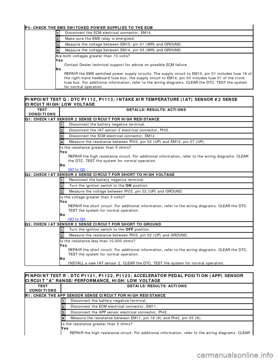
P3: CHECK
THE EMS SWITCHED
POWER SUPPLIES TO THE ECM
D
isconnect the ECM electrical connector, EM14.
1
Make sure the EMS re
lay i
s energized.
2
Meas
ure the voltage between EM10, pin 01 (WR) and GROUND.
3
Meas
ure the voltage between EM14, pin 03 (WR) and GROUND.
4
Are both
voltages greater than 10 volts?
Yes Contact Dealer technical support for advice on possible ECM failure.
No REPAIR the EMS switched power supply circuits. The su pply circuit to EM10, pin 01 includes fuse 18 of
the right-hand heelboard fuse box, the supply circuit to EM14, pin 03 includes fuse 01 of the trunk
fuse box. For additional information, refer to th e wiring diagrams. CLEAR the DTC. TEST the system
for normal operation.
PI
NPOINT TEST Q : DTC P1112, P1113; INTAKE
AIR TEMPERATURE (IAT) SENSOR #2 SENSE
CIRCUIT HIGH/LOW VOLTAGE
TE
ST
CONDITIONS
D
ETAILS/RESULTS/ACTIONS
Q1:
CHECK IAT SENSOR 2 SENSE CIRCUIT FOR HIGH RESISTANCE
Di
sconnect the battery negative terminal.
1
Di
sconnect the IAT sensor 2 electrical connector, PI03.
2
D
isconnect the ECM electrical connector, EM12.
3
Me
asure the resistance between PI03, pin 02 (UP) and EM12, pin 07 (UP).
4
Is th
e resistance greater than 5 ohms?
Yes REPAIR the high resistance circui t. For additional information, refer to the wiring diagrams. CLEAR
the DTC. TEST the system for normal operation.
No GO to Q2
.
Q2: CH
ECK IAT SENSOR 2 SENSE CIRC
UIT FOR SHORT TO HIGH VOLTAGE
R
econnect the battery negative terminal.
1
Turn the ignition swi
tch to the ON
position.
2
Measure the
voltage between PI
03, pin 02 (UP) and GROUND.
3
Is th
e voltage greater than 3 volts?
Yes REPAIR the short circuit. For addi tional information, refer to the wiring diagrams. CLEAR the DTC.
TEST the system for normal operation.
No GO to Q3
.
Q3:
CHECK IAT SENSOR 2 SENSE CIRCUIT FOR SHORT TO GROUND
Turn the ignition swi
tch to the OFF
position.
1
Meas
ure the resistance between PI03, pin 02 (UP) and GROUND.
2
Is
the resistance less than 10,000 ohms?
Yes REPAIR the short circuit. For addi tional information, refer to the wiring diagrams. CLEAR the DTC.
TEST the system for normal operation.
No INSTALL a new IAT sensor 2. CLEAR the DTC. TEST the system for normal operation.
P
INPOINT TEST R : DTC P1121, P1122, P1123;
ACCELERATOR PEDAL POSITION (APP) SENSOR
CIRCUIT "A" RANGE/PERFORMANCE, HIGH/LOW VOLTAGE
TE
ST
CONDITIONS
D
ETAILS/RESULTS/ACTIONS
R1: CHECK THE APP
SENSOR SENSE CIRCUIT FOR HIGH RESISTANCE
Di
sconnect the battery negative terminal.
1
D
isconnect the ECM electrical connector, EM11.
2
Di
sconnect the APP sensor electrical connector, PI42.
3
Meas
ure the resistance between EM11, pin 16 (K) and PI42, pin 05 (K).
4
Is th
e resistance greater than 5 ohms?
Yes REPAIR the high resistance circui t. For additional information, refer to the wiring diagrams. CLEAR
Page 1375 of 2490
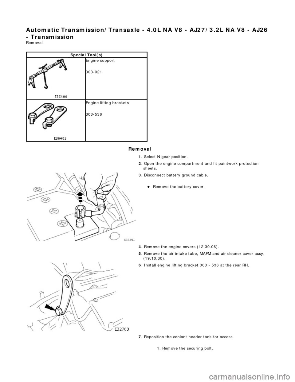
Automatic Transmission/Transaxle - 4.0L NA V8 - AJ27/3.2L NA V8 - AJ26
- Transmission
Removal
Removal
Special Tool(s)
Engine support
303-021
Engine lifting brackets
303-536
1. Select N gear position.
2. Open the engine compartment and fit paintwork protection
sheets.
3. Disconnect battery ground cable.
Remove the battery cover.
4. Remove the engine covers (12.30.06).
5. Remove the air intake tube, MAFM and air cleaner cover assy,
(19.10.30).
6. Install engine lifting bracket 303 - 536 at the rear RH.
7. Reposition the coolant he ader tank for access.
1. Remove the securing bolt.
Page 1387 of 2490
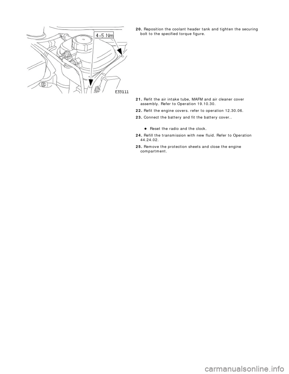
20. Reposition the coolant header tank and tighten the securing
bolt to the specified torque figure.
21. Refit the air intake tube, MAFM and air cleaner cover
assembly. Refer to Operation 19.10.30.
22. Refit the engine covers. re fer to operation 12.30.06.
23. Connect the battery and fit the battery cover..
Reset the radio and the clock.
24. Refill the transmission with new fluid. Refer to Operation
44.24.02.
25. Remove the protection sheets and close the engine
compartment.