1998 JAGUAR X308 air control
[x] Cancel search: air controlPage 1748 of 2490
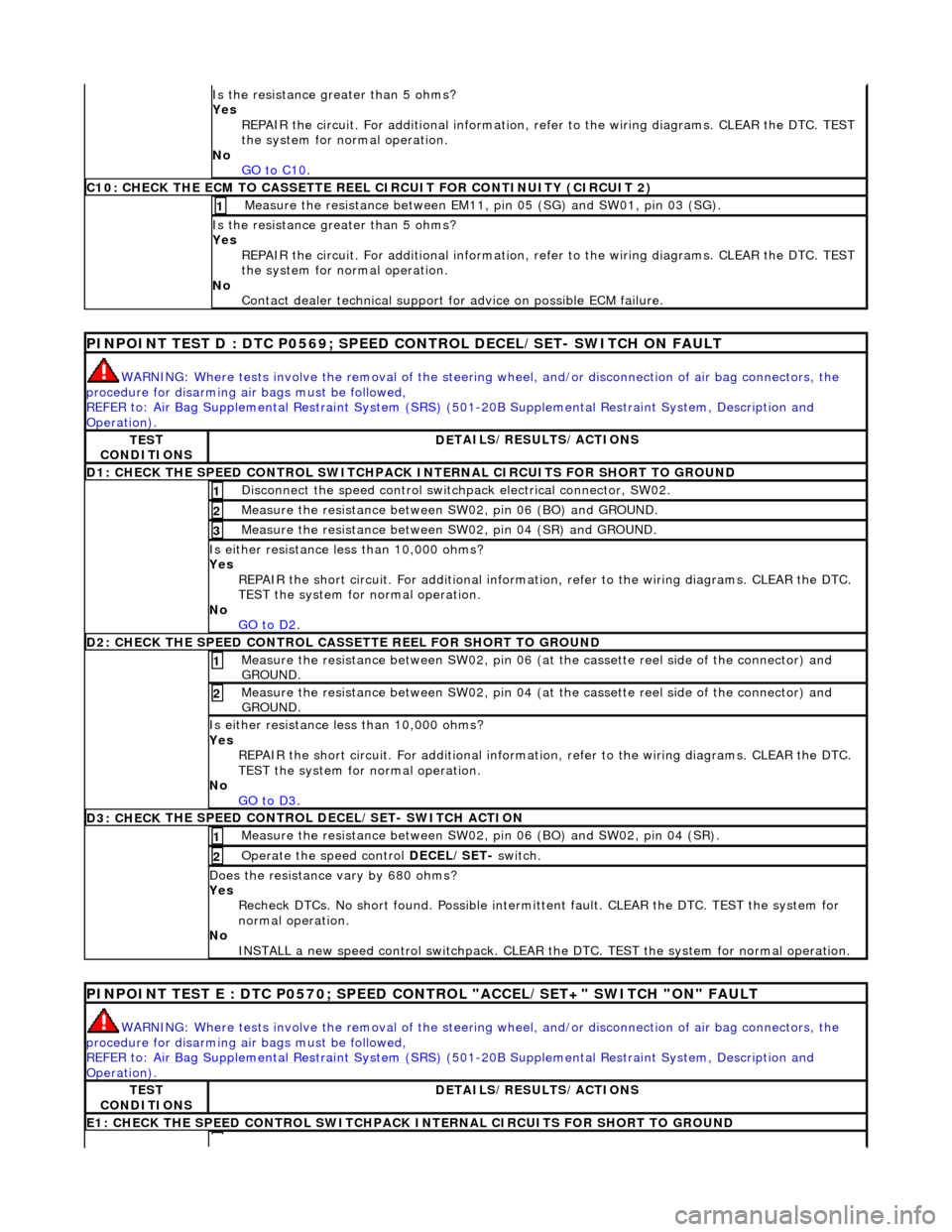
Is the res
istance greater than 5 ohms?
Yes REPAIR the circuit. For additional information, refer to the wiring diagrams. CLEAR the DTC. TEST
the system for normal operation.
No GO to C10
.
C10: CHECK T H
E ECM TO CASSETTE REEL
CIRCUIT FOR CONTINUITY (CIRCUIT 2)
Measure t
he resistance between EM11,
pin 05 (SG) and SW01, pin 03 (SG).
1
Is the res
istance greater than 5 ohms?
Yes REPAIR the circuit. For additional information, refer to the wiring diagrams. CLEAR the DTC. TEST
the system for normal operation.
No Contact dealer technical support for advice on possible ECM failure.
PI
NPOINT TEST D : DTC P0
569; SPEED CONTROL DECEL/SET- SWITCH ON FAULT
WARN
ING: Where tests involve the removal of the steering
wheel, and/or disconnection of air bag connectors, the
procedure for disarming air bags must be followed,
REFER to: Air Bag Supplemental Re straint System (SRS)
(50
1-20B Supplemental Restra
int System, Description and
Operation).
TE S
T
CONDITIONS
D E
TAILS/RESULTS/ACTIONS
D1: CHECK
THE SPEED CONTROL SWITCHPACK IN
TERNAL CIRCUITS FOR SHORT TO GROUND
Disc
onnect the speed control switch
pack electrical connector, SW02.
1
Measure t
he resistance between SW
02, pin 06 (BO) and GROUND.
2
Measure t
he resistance between SW
02, pin 04 (SR) and GROUND.
3
Is either resistance le
ss than 10,000 ohms?
Yes REPAIR the short circuit. For addi tional information, refer to the wiring diagrams. CLEAR the DTC.
TEST the system for normal operation.
No GO to D2
.
D2: CHECK
THE SPEED CONTROL CASSE
TTE REEL FOR SHORT TO GROUND
Me
asure the resistance between SW02, pin 06 (at the cassette reel side of the connector) and
GROUND.
1
M e
asure the resistance between SW02, pin 04 (at the cassette reel side of the connector) and
GROUND.
2
Is either resi stance le
ss than 10,000 ohms?
Yes REPAIR the short circuit. For addi tional information, refer to the wiring diagrams. CLEAR the DTC.
TEST the system for normal operation.
No GO to D3
.
D3: CHECK
THE SPEED CONTROL DECEL/SET- SWITCH ACTION
Meas
ure t
he resistance between SW02,
pin 06 (BO) and SW02, pin 04 (SR).
1
Operate
the speed control
DECEL/SET- switch.
2
Do
es the resistance
vary by 680 ohms?
Yes Recheck DTCs. No short found. Po ssible intermittent fault. CLEAR the DTC. TEST the system for
normal operation.
No INSTALL a new speed control switchpack. CLEAR the DTC. TEST the system for normal operation.
PINPOI
NT TEST E : DTC P0570; SPEED CONTROL "ACCEL/SET+" SWITCH "ON" FAULT
WAR
N
ING: Where tests involve the removal of the steering
wheel, and/or disconnection of air bag connectors, the
procedure for disarming air bags must be followed,
REFER to: Air Bag Supplemental Re straint System (SRS)
(50
1-20B Supplemental Restra
int System, Description and
Operation).
TE S
T
CONDITIONS
D E
TAILS/RESULTS/ACTIONS
E1
: CHECK THE SPEED CONTROL
SWITCHPACK IN
TERNAL CIRCUITS FOR SHORT TO GROUND
Page 1749 of 2490
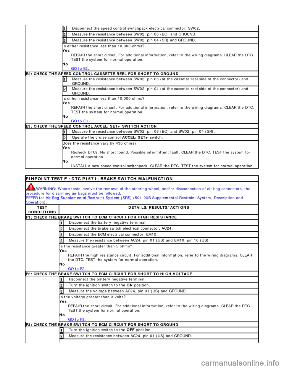
Di
sconnect the speed control switch
pack electrical connector, SW02.
1
Meas
ure the resistance between SW
02, pin 06 (BO) and GROUND.
2
Meas
ure the resistance between SW
02, pin 04 (SR) and GROUND.
3
Is either resi
stance
less than 10,000 ohms?
Yes REPAIR the short circuit. For addi tional information, refer to the wiring diagrams. CLEAR the DTC.
TEST the system for normal operation.
No GO to E2
.
E2
: CHECK THE SPEED CONTROL CASSE
TTE REEL FOR SHORT TO GROUND
M
easure the resistance between SW02, pin 06 (at the cassette reel side of the connector) and
GROUND.
1
M
easure the resistance between SW02, pin 04 (at the cassette reel side of the connector) and
GROUND.
2
Is either resi
stance
less than 10,000 ohms?
Yes REPAIR the short circuit. For addi tional information, refer to the wiring diagrams. CLEAR the DTC.
TEST the system for normal operation.
No GO to E3
.
E3
: CHECK THE SPEED CONTROL
ACCEL/SET+ SWITCH ACTION
Meas
ure the resistance between SW02,
pin 06 (BO) and SW02, pin 04 (SR).
1
Op
erate the cruise control
ACCEL/SET+ switch.
2
D
oes the resistance
vary by 430 ohms?
Yes Recheck DTCs. No short found. Po ssible intermittent fault. CLEAR the DTC. TEST the system for
normal operation.
No INSTALL a new speed control switchpack. CLEAR the DTC. TEST the system for normal operation.
P
INPOINT TEST F : DTC P1571;
BRAKE SWITCH MALFUNCTION
WAR
NING: Where tests involve the removal of the steering
wheel, and/or disconnection of air bag connectors, the
procedure for disarming air bags must be followed,
REFER to: Air Bag Supplemental Re straint System (SRS)
(501-20B Supplemental Restra
int System, Description and
Operation).
TE
ST
CONDITIONS
D
ETAILS/RESULTS/ACTIONS
F1: CHECK THE BRAKE
SWITCH TO
ECM CIRCUIT FOR HIGH RESISTANCE
Di
sconnect the battery negative terminal.
1
Di
sconnect the brake switch electrical connector, AC24.
2
D
isconnect the ECM electrical connector, EM10.
3
Meas
ure the resistance between AC24,
pin 01 (US) and EM10, pin 10 (US).
4
Is th
e resistance greater than 5 ohms?
Yes REPAIR the high resistance circui t. For additional information, refer to the wiring diagrams. CLEAR
the DTC. TEST the system for normal operation.
No GO to F2
.
F2: CHECK THE BRAKE
SWITCH TO ECM
CIRCUIT FOR SHORT TO HIGH VOLTAGE
R
econnect the battery negative terminal.
1
Turn the ignition swi
tch to the ON
position.
2
M
easure the voltage between AC24, pin 01 (US) and GROUND.
3
Is th
e voltage greater than 3 volts?
Yes REPAIR the short circuit. For addi tional information, refer to the wiring diagrams. CLEAR the DTC.
TEST the system for normal operation.
No GO to F3
.
F3: CHECK THE BRAKE
SWITCH TO
ECM CIRCUIT FOR SHORT TO GROUND
Turn the ignition swi
tch to the OFF
position.
1
Meas
ure the resistance between AC24, pin 01 (US) and GROUND.
2
Page 1750 of 2490
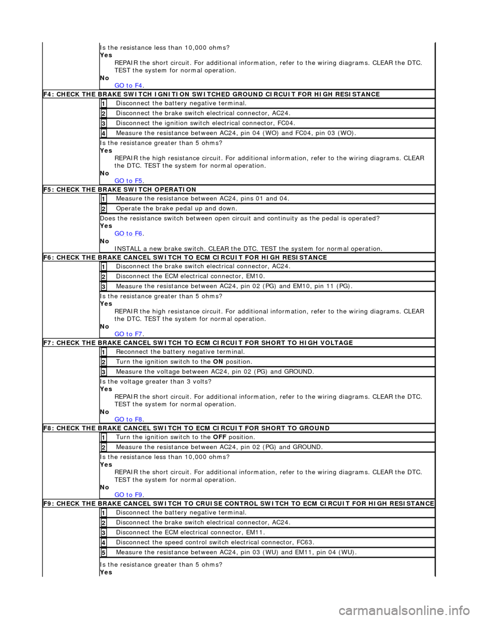
Is t
he resistance less than 10,000 ohms?
Yes REPAIR the short circuit. For addi tional information, refer to the wiring diagrams. CLEAR the DTC.
TEST the system for normal operation.
No GO to F4
.
F4: CHECK THE BRAKE SWITCH IGNITION SWIT
C
HED GROUND CIRCUIT FOR HIGH RESISTANCE
Di
sc
onnect the battery negative terminal.
1
Di
sc
onnect the brake switch electrical connector, AC24.
2
Di
sc
onnect the ignition switch electrical connector, FC04.
3
Measure t
he resistance between AC24,
pin 04 (WO) and FC04, pin 03 (WO).
4
Is the res
istance greater than 5 ohms?
Yes REPAIR the high resistance circui t. For additional information, refer to the wiring diagrams. CLEAR
the DTC. TEST the system for normal operation.
No GO to F5
.
F5: CHECK THE BRAKE SWITCH O
PERATION
Me
asure
the resistance between AC24, pins 01 and 04.
1
O
p
erate the brake pedal up and down.
2
Doe
s
the resistance switch between open circuit and continuity as the pedal is operated?
Yes GO to F6
.
No
INST
ALL a new brake switch. CLEAR the DTC.
TEST the system for normal operation.
F6: CHECK THE BRAKE CANCEL
SWITCH
TO ECM CIRCUIT FOR HIGH RESISTANCE
Disc
onnect the brake switch electrical connector, AC24.
1
D
i
sconnect the ECM electrical connector, EM10.
2
Me
asure
the resistance between AC24, pin 02 (PG) and EM10, pin 11 (PG).
3
Is th
e res
istance greater than 5 ohms?
Yes REPAIR the high resistance circui t. For additional information, refer to the wiring diagrams. CLEAR
the DTC. TEST the system for normal operation.
No GO to F7
.
F7: CHECK THE BRAKE CANCEL
SWITCH TO
ECM CIRCUIT FOR SHORT TO HIGH VOLTAGE
Re
connect the battery negative terminal.
1
Turn the ignition swi
t
ch to the ON
position.
2
Me
asure the voltage between AC24, pin 02 (PG) and GROUND.
3
Is th
e volt
age greater than 3 volts?
Yes REPAIR the short circuit. For addi tional information, refer to the wiring diagrams. CLEAR the DTC.
TEST the system for normal operation.
No GO to F8
.
F8: CHECK THE BRAKE CANCEL
SWITCH
TO ECM CIRCUIT FO R SHORT TO GROUND
Turn the ignition swit
ch to the OFF
position.
1
Measure t
he resistance between AC24, pin 02 (PG) and GROUND.
2
Is
t
he resistance less than 10,000 ohms?
Yes REPAIR the short circuit. For addi tional information, refer to the wiring diagrams. CLEAR the DTC.
TEST the system for normal operation.
No GO to F9
.
F9: CHECK THE BRAKE CANCEL
SWITCH
TO CRUISE CONTROL SWITCH TO ECM CIRCUIT FOR HIGH RESISTANCE
Disc
onnect the battery negative terminal.
1
Di
sc
onnect the brake switch electrical connector, AC24.
2
D
i
sconnect the ECM electrical connector, EM11.
3
Di
sc
onnect the speed control switch electrical connector, FC63.
4
Me
asure
the resistance between AC24, pin 03 (WU) and EM11, pin 04 (WU).
5
Is th
e res
istance greater than 5 ohms?
Yes
Page 1751 of 2490
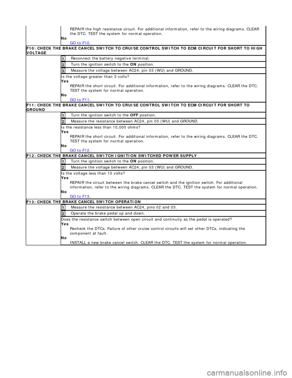
R
EPAIR the high resistance circui
t. For additional information, refer to the wiring diagrams. CLEAR
the DTC. TEST the system for normal operation.
No GO to F10
.
F10: CHECK
THE BRAKE CANCEL SWITCH TO CRUISE CO
NTROL SWITCH TO ECM CIRCUIT FOR SHORT TO HIGH
VOLTAGE
R
econnect the battery negative terminal.
1
Turn the ignition swi
tch to the ON
position.
2
M
easure the voltage between AC24, pin 03 (WU) and GROUND.
3
Is th
e voltage greater than 3 volts?
Yes REPAIR the short circuit. For addi tional information, refer to the wiring diagrams. CLEAR the DTC.
TEST the system for normal operation.
No GO to F11
.
F11: CHECK
THE BRAKE CANCEL SWITCH TO CRUISE
CONTROL SWITCH TO ECM CIRCUIT FOR SHORT TO
GROUND
Turn the ignition swi
tch to the
OFF position.
1
Meas
ure the resistance between AC24, pin 03 (WU) and GROUND.
2
Is
the resistance less than 10,000 ohms?
Yes REPAIR the short circuit. For addi tional information, refer to the wiring diagrams. CLEAR the DTC.
TEST the system for normal operation.
No GO to F12
.
F12: CHECK
THE BRAKE CANCEL SWITCH
IGNITION SWITCHED POWER SUPPLY
Turn the ignition swi
tch to the ON
position.
1
M
easure the voltage between AC24, pin 03 (WU) and GROUND.
2
Is th
e voltage less than 10 volts?
Yes REPAIR the circuit between the brake cancel sw itch and the ignition switch. For additional
information, refer to the wiring diagrams. CLEAR the DTC. TEST the system for normal operation.
No GO to F13
.
F13: CHECK
THE BRAKE CA
NCEL SWITCH OPERATION
Me
asure the resistance between AC24, pins 02 and 03.
1
O
perate the brake pedal up and down.
2
Doe
s the resistance switch between open circuit and continuity as the pedal is operated?
Yes Recheck the DTCs. Failure of other cruise contro l circuits will set other DTCs, indicating the
component at fault.
No INSTALL a new brake cancel switch. CLEAR the DT C. TEST the system for normal operation.
Page 1752 of 2490
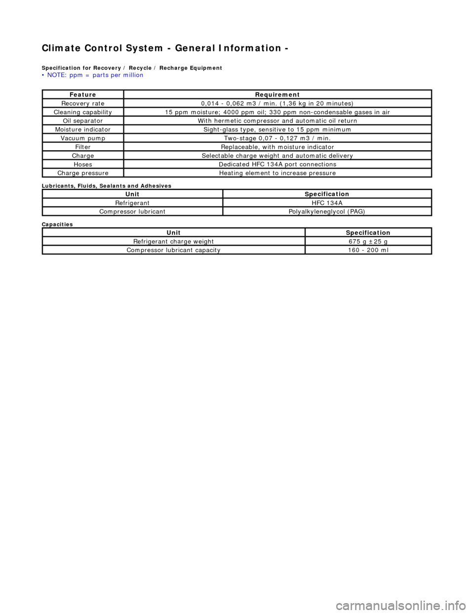
Climate Control System - General Informatio
n -
Sp
ecification for Recovery / Recycle / Recharge Equipment
•
NOTE: ppm = parts per million
Lubri
c
ants, Fluids, Sealants and Adhesives
Capacities
Fe at
ure
R
e
quirement
R
e
covery rate
0
,
014 - 0,062 m3 / min. (1,36 kg in 20 minutes)
Cleaning capability1
5 ppm
moisture; 4000 ppm oil; 330 ppm non-condensable gases in air
O
il se
parator
W
i
th hermetic compressor
and automatic oil return
Mois
ture indicator
Sigh
t-glass type, sensit ive to 15
ppm minimum
Vacuu
m
pump
Two-s
t
age 0,07 - 0,127 m3 / min.
Fi
lt
er
Replaceable, w
i
th
moisture indicator
ChargeSele
ctable charge weight and automatic delivery
HosesD
e
dicated HFC 134A port connections
Charge pressu
reHe
ating element to increase pressure
UnitS
p
ecification
Re
fr
i
geran
tHFC 134
A
Compressor lubricantP
ol
yalkyleneglycol (PAG)
UnitS
p
ecification
Re
fr
i
geran
t ch
ar
ge we
ight675 g ±2 5 g
Compressor lubricant capacity160
- 200 ml
Page 1753 of 2490
Climate Co
ntrol System - General In
formation - Climate Control System
Description an
d Operation
CAUTION: Observe all relevant safety requirements. Wear suitable eye and skin protection Do not mix HFC 134A and
CFC 12 refrigerants. Do not vent refrigerant directly to atmosphere and always use Jaguar approved recovery, recycle and
recharge equipment. Note the amount of recovered refrigerant; it will indicate the state of the system.
Working Practices
Be aware o
f, and comply with al
l health and safety requirements , whether they be legislative or common sense. This applies
to conditions set both for the operator and workshop.
Before commencing any repair or service procedure, disconnect the vehicle battery ground lead and protect the vehicle,
where appropriate, from dirt or damage.
Work in a well ventilated, clean and tidy area.
Keep all components and tools clean.
Recovery, recycle and recharge equipment must meet, or ex ceed, the requirements detailed in the Specification sub-
section.
Handling Refrigerant
We
ar eye protection at all times. Use gloves and keep all
skin covered that may come into contact with refrigerant.
Should refrigerant come into co ntact with eyes or skin, wash the affected area with cool water and seek medical advice; do
not attempt to treat the condition yourself.
Avoid breathing refrigerant vapor; it may cause irritation to the respiratory system.
CAUTION: Never use high pressure comp ressed air to flush out a system. Under certain ci rcumstances a combination
of HFC 134A refrigerant, compressed air and a source of combus tion (welding and brazing operations in the vicinity), may
result in an explosion and the release of potentially toxic compounds.
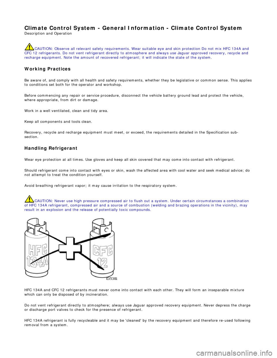
HFC 134A and CFC 12 refrigerants must neve r come into contact with each other. They will form an inseparable mixture
which can only be disposed of by incineration.
Do not vent refrigerant directly to atmo sphere; always use Jaguar approved recove ry equipment. Never depress the charge
or discharge port valves to check for the pr esence of refrigerant.
HFC 134A refrigerant is fully recycleable and it may be 'cleaned' by the recovery equipment and therefore re-used following
removal from a system.
Page 1758 of 2490
Climate Control System - General Informatio
n - Climate Control System
D
iagn
osis and Testing
I
n
troduction
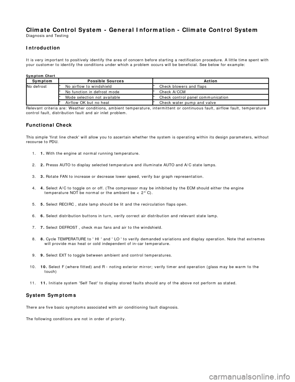
It is very i
m
portant to positive
ly identify the area of concern before starting a rectification procedure. A little time spent with
your customer to identify the conditions under which a pr oblem occurs will be beneficial. See below for example:
Sym
ptom Chart
Re
lev
ant criteria are: Weather conditions,
ambient temperature, intermittent or cont inuous fault, airflow fault, temperature
control fault, distribution fault and air inlet problem.
Functio n
al Check
This
s
imple 'first line check' will allo
w you to ascertain whether the system is operating within its design parameters, withou t
recourse to PDU.
1. 1. With the engine at normal running temperature.
2. 2. Presss AUTO to display selected temperature and illuminate AUTO and A/C state lamps.
3. 3. Rotate FAN to increase or decrease lowe r speed, verify bar graph representation.
4. 4. Select A/C to toggle on or off. (T he compressor may be inhibited by the ECM should either the engine
temperature NOT be normal or the ambient be < 2° C).
5. 5. Select RECIRC , state lamp should be lit and the recirculation flaps open.
6. 6. Select distribution butt ons in turn, verify correct air distribution and relevant state lamp.
7. 7. Select DEFROST , check max fans and air to the windshield.
8. 8. Cycle TEMPERATURE to ' HI ' and ' LO ' to verify demanded variations and display operation. Note that extremes
will provide max heat or cold independent of in-car temperature.
9. 9. Select EXT to toggle between am bient and control temperatures.
10. 10. Select F (where fitted) and R - noting exterior mirror; verify timer and operation (glass may be warm to the
touch)
11. 11. Initiate system 'Self Test' to display stored faul ts should any of the above not perform as stated.
Sy
stem Symptoms
There
are five
basic symptoms associated
with air conditioning fault diagnosis.
The following conditions are not in order of priority.
Sy m
ptom
Possib
l
e Sources
Acti
o
n
N
o defrostN o
airflow to windshield
*
Check blower s and flaps
*
N o functi
on in defrost mode
*
Check A/CCM
*
Mo de s
election not available
*
Chec k
control panel communication
*
Ai rfl
ow OK but no heat
*
Check water pu
mp and valve
*
Page 1762 of 2490
Climate Control System - General Infor
mation - Air Conditioning (A/C)
System Recovery, Evacuation and Charging
Gen e
ral Procedures
Recover / Reclaim
Ev
acuation
Charging
1.
CAUTIO
N: Read the procedures and instructions supplied
by the manufacturer of the air co nditioning service center before
commencing any process requiring the handling of refrigerant. In
addition to the manufacturer's in formation, observe all safety
precautions and advice deta iled in this section.
Disconnect battery ground lead; refer to 86.15.19.
2. Remove passenger side fi
rewall cover.
3. Remove driver side firewall cover.
4. Remove engine compar tment rear cover.
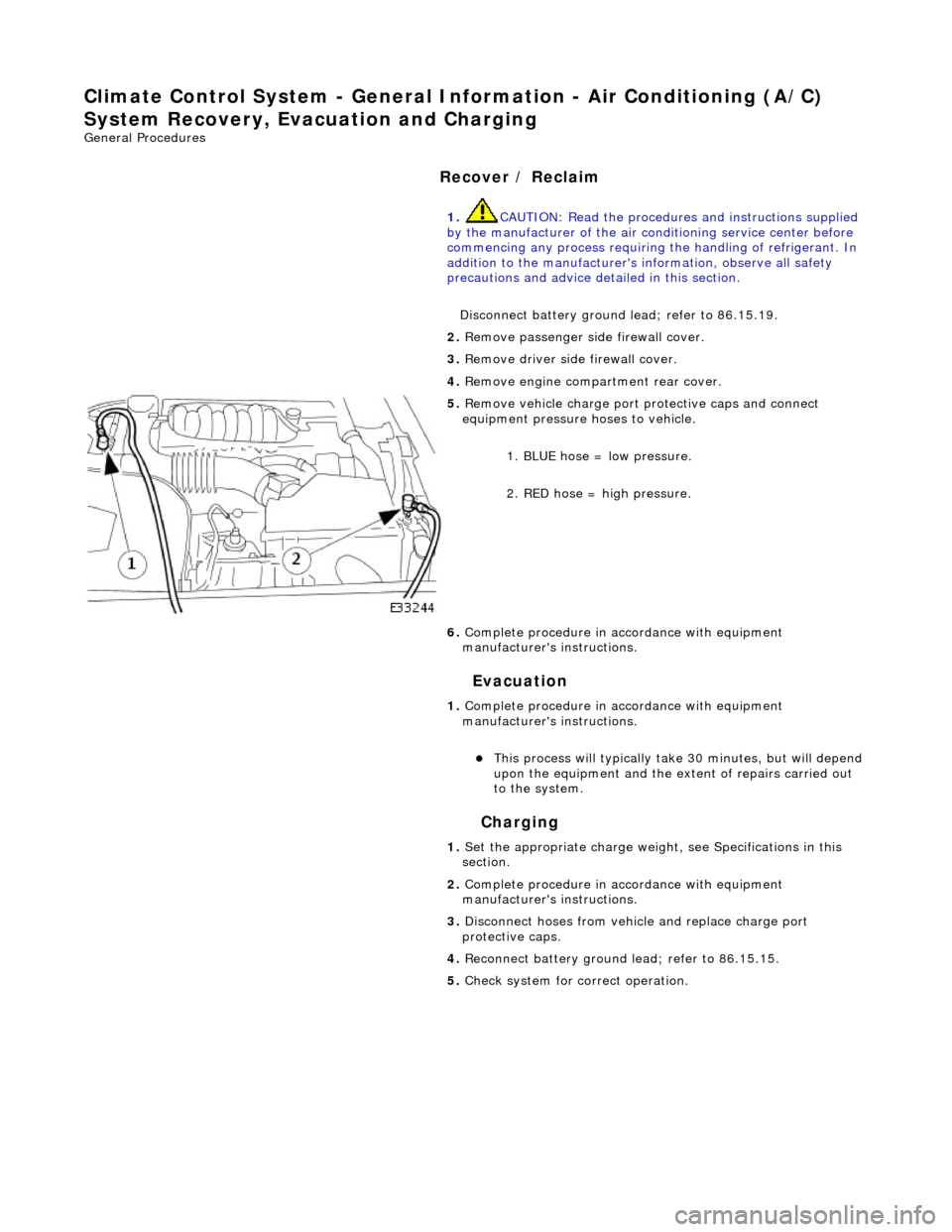
5. Re
move vehicle charge port
protective caps and connect
equipment pressure hoses to vehicle.
1. BLUE hose = low pressure.
2. RED hose = high pressure.
6. Complete procedure in ac cordance with equipment
manufacturer's instructions.
1. Complete procedure in ac cordance with equipment
manufacturer's instructions.
This proc
ess will typically ta
ke 30 minutes, but will depend
upon the equipment and the ex tent of repairs carried out
to the system.
1. Set the appropriate charge weight, see Specifications in this
section.
2. Complete procedure in ac cordance with equipment
manufacturer's instructions.
3. Disconnect hoses from vehicle and replace charge port
protective caps.
4. Reconnect battery ground lead; refer to 86.15.15.
5. Check system for correct operation.