Page 477 of 2490
Stee
ring System - General Informat
ion - Steering Gear Centralizing
Gen
eral Procedures
Rack Al
ignment Markers
1.
The steering rack should al
ways
be centralized prior to steering
column or suspension geometry adjustment.
Central
ization of the steering ra
ck is achieved by aligning
the marker on the centralizing cap with a locator on the
pinion housing.
Page 478 of 2490
Power Steering -
Lubric
ants, Fluids, Sealants and Adhesives
Capacities
Torques
UnitSp
ecification
PAS flu
i
d
De
xr
on 3
UnitLi
t
ers
PAS syste
m1,0
PAS reservoi
r0,4
Com p
onent
Nm
Rac
k
mountin
g brac
ke
t to suspension crossbeam
40
- 50
PAS pump to front mounti
ng bracket
22
-
26
P
AS pu
mp assembly to cylinder block
38
-
48
Pul
l
ey to PAS pump
18
-
24
Hi
gh pressure hose to PAS pump22 -
28
Rack
pipe latch plate bolt8.5 -
11.5
R
e
servoir mounting bracket to body nuts
4 -
5
R
e
servoir mounting bracket clamp
4 -
5
Fluid cooler to body2.
5 -
3.5
Transfer pipe
to steering rack7 -
8
Transfer pipe
to hydraulic con
trol valve
7 -
8
Page 480 of 2490

The steering rack assembly :
Is mounted on the
rear face of the
front suspension crossbeam by two forg ed mounting brackets with resilient
bushes. The bushes are handed (pinion side and non-pinion side) and are orientated according to the vehicle range
application.
Convert s
the rotary motion of the steering wheel, via the steering gear pinion, to the lateral motion of the rack.
F
e
atures a variable ratio steering
rack with integral hydraulic po wer steering cylinder and piston.
Has a hydrauli
c control valve with Servotronic co
ntrol and positive center feel torsion bar.
The basic steering rack assembly is not serviceable. The following components are serviceable items:
Transfer pipework
.
Servotronic valve. Cent
ralizing cap.
O
u
ter ball joint.
Rac
k
gaiter.
Clips and
fittings.
Steering Rack Components
It e
m
Par
t
Number
De
scr
iption
1—Front
su
spension crossbeam
2—Steeri
ng rack housi
ng
3—Hydraulic
control valve housing
4—Moun
ting bracke
t
5—Gait
er
6—Tie
rod
7—O
u
ter ball joint
Steering R
a
ck Assembly
Page 488 of 2490

The rotary distri
butor and control sleeve turn relative to ea
ch other, forming the unequal restrictions which create the
differential pressures to operat e the rack piston; the displacement of the di stributor and sleeve being controlled by the
elastic deformation of a torsion bar which is concentric with the pinion and valve. Refer to Positive Center-Feel Torsion Bar
in this sub-sectio n.
The hydraulic reaction piston moves axially, relative to th e rotary distributor, and is connected to the control sleeve by a
three-bearing helical screw. Pressure applied either side of the hydraulic reaction piston is translated into a rotational force
which increases steering effort. For detail s of Servotronic speed-sensitive steering control, refer to Servotronic Control in
this sub-section.
When the vehicle is travelling straight ah ead, the valve restrictions are balanced, thus providing equal pressures on either
side of the rack piston. When load is a pplied at the steering wheel, the two halves of the control valve (rotary distributor
and control sleeve) are displaced making the restrictions unequa l. The resulting differential pressures on either side of the
rack piston, assist the steering rack to mo ve to left or right. As the turning load is removed, the pressures equalize again
and the steering return s to the straight ahead position , aided by suspension geometry.
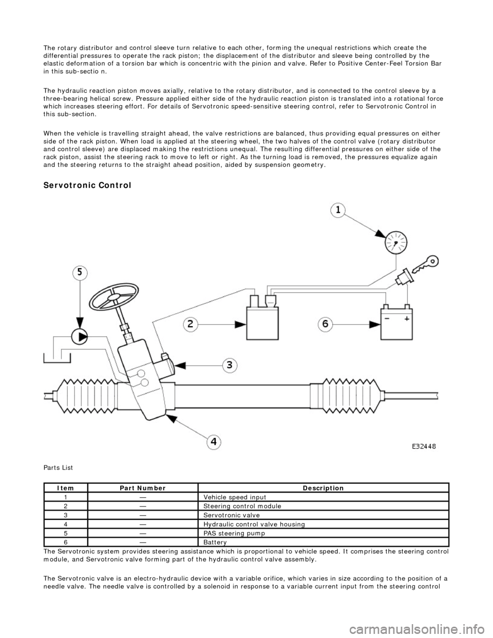
Serv
otronic Control
P a
rts List
The Servotronic system provides steering assistance which is pr oportional to vehicle speed. It comprises the steering control
module, and Servotronic valve forming part of the hydraulic control valve assembly.
The Servotronic valve is an electro-hydrauli c device with a variable orifice, which varies in size according to the position of a
needle valve. The needle valve is controlled by a solenoid in response to a variable current input from the steering control
Ite
m
Part
Number
Descr
iption
1—Vehi
cl
e speed input
2—Steeri
ng control
module
3—Servotronic valve
4—Hydraulic
control valve housing
5—PAS stee
rin
g pump
6—Batt
ery
Page 489 of 2490

modul
e. This regulates the fluid flow
through the hydraulic control valve, wh ich determines the amount of steering
assistance.
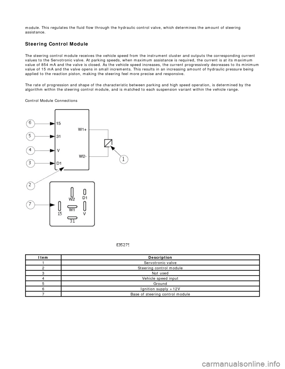
Steering Control Module
The steering control
module re
ceives the vehicle speed from the instrument cluster and outputs the corresponding current
values to the Servot ronic valve. At parking speeds, wh en maximum assistance is required , the current is at its maximum
value of 854 mA and the valve is closed. As the vehicle speed increases, the current progressively decreases to its minimum
value of 15 mA and the valve opens in sma ll increments. This results in an increasing amount of hydraulic pressure being
applied to the reaction piston, making the steering feel more precise and responsive.
The rate of progression and shape of the characteristic between parking and high speed operation, is determined by the
algorithm within the steering control module, and is matched to each suspension variant within the vehicle range.
Control Module Connections
It
em
De
scription
1Servotronic valve
2Steeri
ng control module
3No
t used
4Vehi
cle speed input
5Ground
6Ignition su
pply +12V
7Base of
steering control module
Page 510 of 2490
The lower steeri ng col
umn:
Is a han
ded assembly
.
Incorporates
a col
umn to toeboard seal
which comprises a rolling element having two, low friction, PTFE rings. The
rolling element locates in a rubber b oot which seals to the toeboard.
Has a lowe
r universal joint connecting the
lower column to the steering rack.
Has an upper un
iversal joint connecting
the lower column to the upper column.
Has a NVH damper in
corporated into
the upper universal joint assembly.
May be installed in an
y orientation on the universal joint splines.
R
e
quires no setting or adjustment.
Has no s
e
rviceable components.
It is essential to disconnect the lower column from the steer ing rack before removing the engine or front suspension
crossbeam.
It e
m
Par
t
Number
De
scr
iption
1-Boot
2-Uni
v
ersal joint to upper column
3-Lower steeri
ng col
umn shaft
4-R
e
taining bolts
5-Uni
v
ersal joint to steering rack
Lower Steering Column
Page 1522 of 2490
Exhaust System -
Torques
ComponentNm
Nut - Downpipe catalytic converter to exhaust manifold14 - 18
Bolt - Downpipe catalytic converter to lower mounting bracket39 - 51
Bolt - Front muffler mounting to gearbox (SC)22 - 28
Bolt - Front muffler mounting to front muffler cross brace (SC)22 - 28
Bolt - Over-axle mounting to rear suspension A-frame22 - 28
Torca clamps52 - 68
Oxygen sensor to downpipe40 - 50
Page 2124 of 2490
Seating - Front Seat Backrest
Removal and Installation
Removal
1. Remove front seat for ac cess. Refer to 76.70.01.
2. Remove seat back fini sher. Refer to 76.70.09.
3. Remove front seat headrest. Refer to 76.70.14.
4. Release the five squab cover to seat frame securing strips.
5. Release the squab cover to seat frame lower securing clips.
6. Remove the four squab pad to squab suspension hog rings.
7. Sever the two ratchet straps securing squab pad to squab
suspension.