Page 2032 of 2490
Front End Body Panels - Radiator Grille Opening Panel Reinforcement Removal and Installation
Removal
Installation
1.
Remove radiator grilles. Refer to 76.55.03.
2. Remove radiator grille surround. (Refer to 76.55.15)
3. Open hood.
4. Fit front fender cover.
5. Slacken headlamp trim panel to headlamp securing screw.
6. Carefully release headlamp trim panel fir tree fastener from BIW
and remove panel from vehicle.
7. Remove securing screw from trim panel and remove and discard fir
tree fastener.
1. Fit new fir tree fastener to headlamp trim panel.
2. Fit but do not tighten securing screw to headlamp trim panel.
3. Position headlamp trim panel on BIW front panel, locating securing
screw in headlamp slot.
4. Fully seat fir tree fastener in BIW front panel.
5. Finally tighten headlamp trim panel securing screw.
6. Close hood and remove fender cover.
7. Fit radiator grill surround. Refer to 76.55.15
8. Fit radiator grilles. Refer to 76.55.03.
Page 2033 of 2490
Front End Body Panels - Radiator Splash Shield Removal and Installation
Removal
Installation
1.
Raise front of vehicle and support on stands.
2. Remove and discard seven scrivets securing undertray to bumper
cover.
3. Remove and discard tiestrap securi ng undertray to crossbeam front
brace.
4. At each side of vehicle, remo ve and discard scrivet securing
undertray to wheelarch liner.
5. Remove undertray and wind deflectors from vehicle.
6. Remove and discard plastic scrivet s securing wind deflectors to
undertray.
1. Position wind deflector on undertray and secure with new scrivets.
2. Position liners in wheelarches.
3. Position undertray assembly unde r vehicle and using new plastic
fixings, secure assembly to wheelarch liners.
4. Position undertray/wind deflector a ssembly on vehicle and secure to
front bumper using new plastic scrivets.
5. Fit road wheels.
6. Lower vehicle from stands.
Page 2043 of 2490
Installation
9. Remove hood insulation pad.
Slacken and remove the hood insulation pad securing
screws and remove insulation pad from hood.
Remove and discard the screw inserts
10. Remove hood striker assemb lies. Refer to 76.16.24.
11. Slacken and remove strut pivots from hood inserts.
12. Remove masking tape from hood.
1. Fit and fully tighten strut pivots in hood inserts.
2. Fit but do not tighten hood striker assemblies. Refer to
76.16.24.
3. Fit new insulating pad retaining screw inserts.
4. Position insulating pad on h ood underside and secure with
screws.
5. Apply protective masking tape to forward edge of hood behind
radiator grill.
6. Position hood front seal and fi t and fully seat retaining pegs.
7. Position and fully suppo rt hood on vehicle.
8. Fit but do not tighten hinge se curing bolts, ensuring that
ground strap is attached to correct bolt on LH hinge.
Page 2045 of 2490

Body Closures - Hood Hinge
Removal and Installation
Removal
Installation
1.
CAUTION: Before slackening hi nge bolts, ensure that the
hood is sufficiently supported to prevent damage to paintwork
and gas support struts.
Remove cover from battery and disconnect ground cable from
battery terminal. Refer to 86.15.19.
2. Open hood and fit fender covers.
3. Remove radiator grille. Refer to 76.55.03.
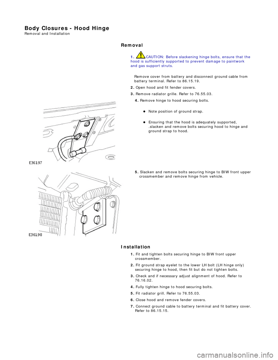
4. Remove hinge to hood securing bolts.
Note position of ground strap.
Ensuring that the hood is adequately supported,
.slacken and remove bolts se curing hood to hinge and
ground strap to hood.
5. Slacken and remove bolts securi ng hinge to BIW front upper
crossmember and remove hinge from vehicle.
1. Fit and tighten bolts securing hinge to BIW front upper
crossmember.
2. Fit ground strap eyelet to the lower LH bolt (LH hinge only)
securing hinge to hood, then fit but do not tighten bolts.
3. Check and if necessary adjust alignment of hood. Refer to
76.16.02.
4. Fully tighten hinge to hood securing bolts.
5. Fit radiator grill. Refer to 76.55.03.
6. Close hood and remove fender covers.
7. Connect ground cable to battery terminal and fit battery cover.
Refer to 86.15.15.
Page 2099 of 2490

Exterior Trim and Ornamentation - Exterior Trim
Description and Operation
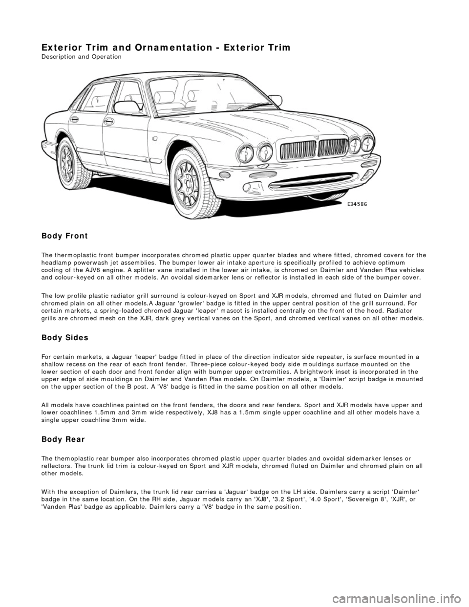
Body Front
The thermoplastic front bumper incorporates chromed plastic upper quarter blades and where fitted, chromed covers for the headlamp powerwash jet assemblie s. The bumper lower air intake aperture is specifically profiled to achieve optimum
cooling of the AJV8 engine. A splitter vane installed in the lowe r air intake, is chromed on Daimler and Vanden Plas vehicles
and colour-keyed on all other models. An ov oidal sidemarker lens or reflector is installed in each side of the bumper cover.
The low profile plastic radiator grill surround is colour-keyed on Sport and XJR mo dels, chromed and fluted on Daimler and
chromed plain on all other models .A Jaguar 'growler' badge is fitted in the upper central positi on of the grill surround. For
certain markets, a spring-loaded chromed Ja guar 'leaper' mascot is installed centrally on the front of the hood. Radiator
grills are chromed mesh on the XJR, dark grey vertical vanes on the Sport, and chromed ve rtical vanes on all other models.
Body Sides
For certain markets, a Jaguar 'l eaper' badge fitted in place of the direction indicator side re peater, is surface mounted in a
shallow recess on the rear of each fro nt fender. Three-piece colour-keyed body side mouldings surface mounted on the
lower section of each door and front fender align with bumper upper extremities. A brightwork inset is incorporated in the
upper edge of side mouldings on Daimler and Vanden Plas models. On Daimler models, a 'Daimler' script badge is mounted
on the upper section of the B post. A 'V8' badge is fitted in the same position on all other models.
All models have coachlines painted on th e front fenders, the doors and rear fender s. Sport and XJR models have upper and
lower coachlines 1.5mm an d 3mm wide respectively, XJ8 has a 1.5mm single upper coachline and all other models have a
single upper coachline 3mm wide.
Body Rear
The themoplastic rear bumper also inco rporates chromed plastic upper quarter blades and ovoi dal sidemarker lenses or
reflectors. The trunk lid trim is colour-keyed on Sport and XJ R models, chromed fluted on Daimler and chromed plain on all
other models.
With the exception of Daimlers, the trunk lid rear carries a 'Jaguar' badge on the LH side. Daimlers carry a script 'Daimler'
badge in the same location. On th e RH side, Jaguar models carry an 'XJ8', '3.2 Sport', '4.0 Sport', 'Sovereign 8', 'XJR', or
'Vanden Plas' badge as applic able. Daimlers carry a 'V8' badge in the same position.
Page 2109 of 2490
Exterior Trim and Ornamentation - Radiator Grille
Removal and Installation
Removal
Installation
1. Slacken and remove the two scre ws securing top of grill to
surround.
2. Lift grill to withdraw retainin g lugs from slots and remove
grill from vehicle.
3. Remove and discard the two ny lon screw inserts from top of
surround (adapters for su percharged models).
4. Repeat above steps to remove grill on opposite side.
1. Fit new screw inserts/adapters to top of grill surround.
2. Fit grill lower lugs into suurround slots.
3. Fit and tighten the two screws securing top of grill to surround.
4. Repeat above steps to instal l grill on opposite side.
Page 2110 of 2490
Exterior Trim and Ornamentation - Radiator Grille Bezel
Removal and Installation
Removal
Installation
1.
Remove radiator grills for access. Refer to 76.55.03.
2. Slacken and remove the two screws securing each end of
surround to BIW and remove surround from vehicle.
3. Remove and discard the two nylon screw inserts from each
side of BIW.
1. Fit new screw inserts to BIW locations.
2. Position grill surround on BIW and fit and tighten securing
screws.
3. Fit radiator grills. Refer to 76.55.03.
Page 2344 of 2490

Bumpers - Front Bumper
Removal and Installation
Removal
WARNING: ENSURE THAT ALL PERSONNEL AND EQUIPMENT ARE CLEAR OF AREA BEFORE OPERATING RAMP.
1. Position vehicle on 4-post ramp.
2. Remove battery cover and disc onnect ground cable from
battery terminal. Refer to 86.15.19
3. Remove radiator surround and grill. Refer to 76.55.15 and
76.55.03.
4. Raise ramp to working height.
5. Using wheel-free lifts, remove front wheels.
6. Remove wheelarch liners for access.
7. Remove undertray. Refer to 76.22.90.
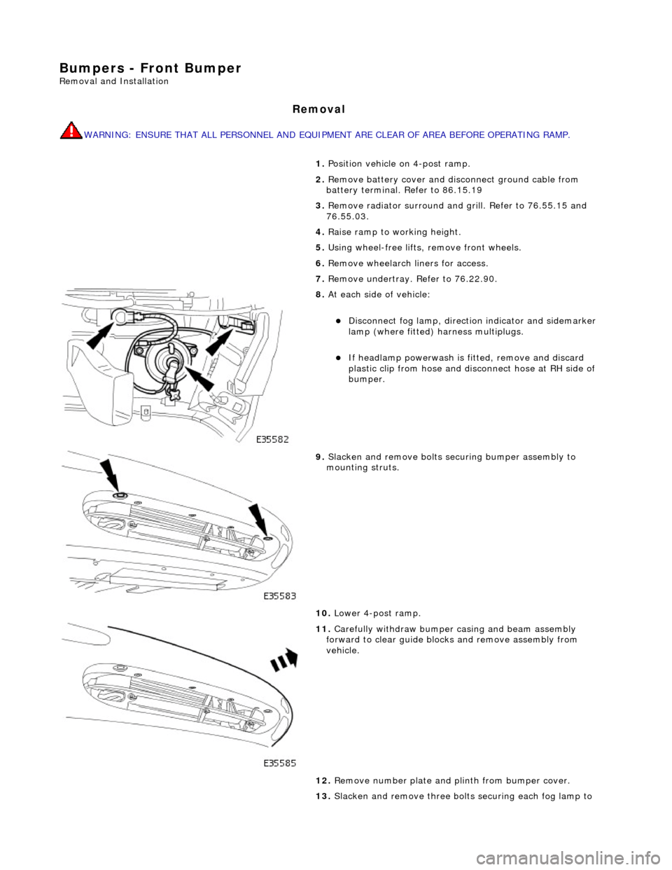
8. At each side of vehicle:
Disconnect fog lamp, directio n indicator and sidemarker
lamp (where fitted) harness multiplugs.
If headlamp powerwash is fitted, remove and discard
plastic clip from hose and disconnect hose at RH side of
bumper.
9. Slacken and remove bolts securing bumper assembly to
mounting struts.
10. Lower 4-post ramp.
11. Carefully withdraw bumper casing and beam assembly
forward to clear guide blocks and remove assembly from
vehicle.
12. Remove number plate and plinth from bumper cover.
13. Slacken and remove three bolts securing each fog lamp to