Page 1810 of 2490
14. Disconnect compressor to condenser discharge line from
condenser.
1. Remove bolt.
2. Discard O-ring seal.
3. Install suitable blanking plugs.
15. Disconnect condenser to receiver / drier line from receiver /
drier.
1. Remove bolt.
2. Discard O-ring seal.
3. Install suitable blanking plugs.
16. Remove radiator retaining panel.
1. Remove panel.
2. Remove mounting bushes.
17. Disconnect hood switch harness connector.
Page 1811 of 2490
Installation
18. Remove radiator / condenser assembly.
Clean coolant spillage from radiator lower carrier panel.
19. Separate condenser from radiator.
1. Remove bolts.
2. Remove condenser.
20. If necessary, remove condenser to receiver / drier line from
condenser.
Remove bolt.
Detach hose from clip.
Discard O-ring seal.
Install suitable blanking plugs.
1. If necessary, renew radiator top and bottom foam sealing
strips.
Page 1812 of 2490
2. If previously removed, install condenser to receiver / drier line
at condenser.
Remove blanking plugs.
Install new O-ring seal and lubricate with clean
compressor oil.
Install bolt (8-10 Nm).
Locate hose to clip.
3. Install condenser to radiator.
Install bolts (8-10 Nm).
4. Install radiator / condenser assembly.
5. Connect condenser to receiver / dr ier line at receiver / drier.
Remove blanking plugs.
Install new O-ring seal and lubricate with clean A/C
compressor oil.
Page 1813 of 2490
Connect hose.
Install bolt (8-10 Nm).
6. Connect compressor to condenser discharge line at condenser.
Remove blanking plugs.
Install new O-ring seal an d lubricate with clean A/C
compressor oil.
Connect hose.
Install bolt (8-10 Nm).
7. Connect transmission o il cooler upper pipe.
Remove blanking plugs.
Install new O-ring seal and lu bricate with clean automatic
transmission fluid.
Connect union nut to radiator and tighten.
8. Connect transmission oil cooler lower pipe.
Remove blanking plugs.
Install new O-ring seal and lu bricate with clean automatic
transmission fluid.
9. Connect radiator blee d hose to radiator.
Page 1814 of 2490
10. Connect radiator top hose to radiator.
1. Connect top hose.
2. Reposition and tighten hose clip.
11. Install radiator retaining panel.
Install bolts and sequenti ally tighten from center
outwards.
12. Connect radiator bottom hose to radiator.
1. Connect bottom hose.
2. Reposition and tighten hose clip.
13. Install twin fan and motor as sembly; refer to 26.25.12.
14. Connect pressure switch.
Page 1859 of 2490
Horn - Horn
Description and Operation
The horns, located behind the radiator gril le, each side of the radiator, are controlled by the Body Processor Module (BPM),
as described below.
The switch, located on the steering wheel pad, is operated, it signals the BPM to sound the horn. The BPM responds by
providing an earth from the horn-output to the horn relay coil. The relay contacts are subsequently closed and the horns
sound.
The horn operating relay, R6 is located in the engine compartm ent fusebox at the left hand side of the engine compartment.
Page 1890 of 2490

Generator and Regulator - Generator4.0L NA V8 - AJ27/3.2L NA V8 - AJ26
Removal and Installation
Removal
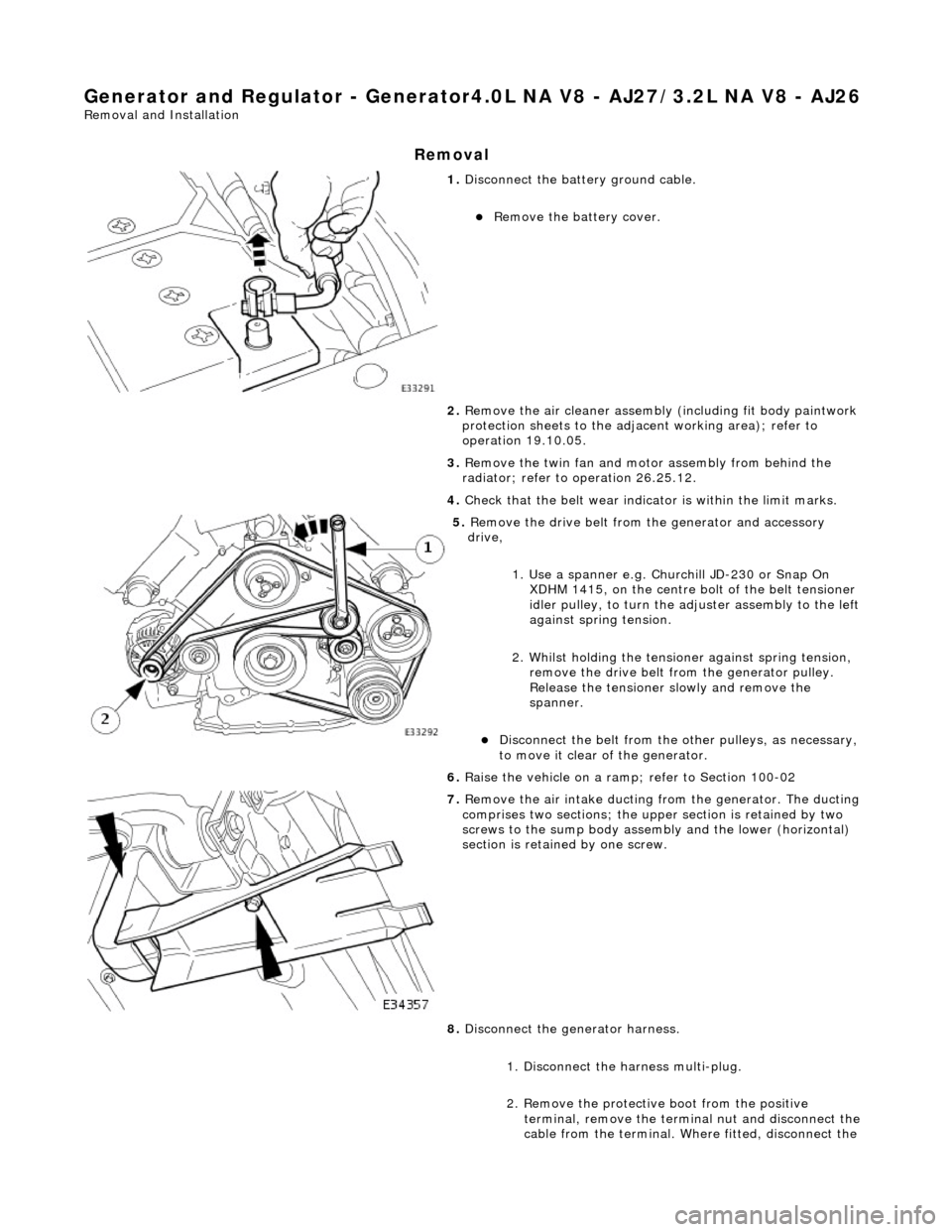
1. Disconnect the batt ery ground cable.
Remove the battery cover.
2. Remove the air cleaner assembly (including fit body paintwork
protection sheets to the adja cent working area); refer to
operation 19.10.05.
3. Remove the twin fan and moto r assembly from behind the
radiator; refer to operation 26.25.12.
4. Check that the belt wear indicator is within the limit marks.
5. Remove the drive belt from the generator and accessory
drive,
1. Use a spanner e.g. Churchill JD-230 or Snap On XDHM 1415, on the centre bo lt of the belt tensioner
idler pulley, to turn the adju ster assembly to the left
against spring tension.
2. Whilst holding the tensioner against spring tension, remove the drive belt from the generator pulley.
Release the tensioner sl owly and remove the
spanner.
Disconnect the belt from the ot her pulleys, as necessary,
to move it clear of the generator.
6. Raise the vehicle on a ramp; refer to Section 100-02
7. Remove the air intake ducting fr om the generator. The ducting
comprises two sections; the upper section is retained by two
screws to the sump body assembly and the lower (horizontal)
section is retained by one screw.
8. Disconnect the generator harness.
1. Disconnect the harness multi-plug.
2. Remove the protective boot from the positive
terminal, remove the termin al nut and disconnect the
cable from the terminal. Where fitted, disconnect the
Page 1891 of 2490
suppression module positive cable from the positive
terminal.
3. Where fitted, remove the nut which secures the
suppression module negati ve cable and disconnect
the cable from the generator. Reposition the
suppression module harness clear of the generator.
9. Remove the lower mounting bolt and reposition the harness
mounting bracket.
10. Remove the upper securing bolt and withdraw the generator
from the mounting bracket.
11. Carefully, manoeuvre the ge nerator forward towards the
radiator.
12. Change the position of the ge nerator and remove it upwards
between the engine and the radiator.