1998 JAGUAR X308 ABS
[x] Cancel search: ABSPage 1787 of 2490
Heating and Ventilation - Heater Core
Removal and Installation
Removal
Installation
1.
Drain radiator coolant only; re fer to 26.10.01 or (SC) 26.10.01.
2. Remove instrument panel for access; refer to 76.46.01.
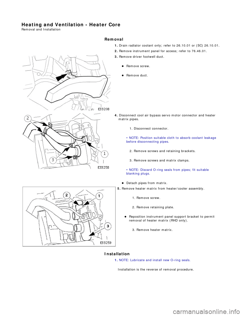
3. Remove driver footwell duct.
Remove screw.
Remove duct.
4. Disconnect cool air bypass serv o motor connector and heater
matrix pipes.
1. Disconnect connector.
• NOTE: Position suitable clot h to absorb coolant leakage
before disconnecting pipes.
2. Remove screws and retaining brackets.
3. Remove screws and matrix clamps.
• NOTE: Discard O-ring seals from pipes; fit suitable
blanking plugs.
Detach pipes from matrix.
5. Remove heater matrix from heater/cooler assembly.
1. Remove screw.
2. Remove retaining plate.
Reposition instrument panel support bracket to permit
removal of heater matrix (RHD only).
3. Remove heater matrix.
1. NOTE: Lubricate and install new O-ring seals.
Installation is the reverse of removal procedure.
Page 1803 of 2490
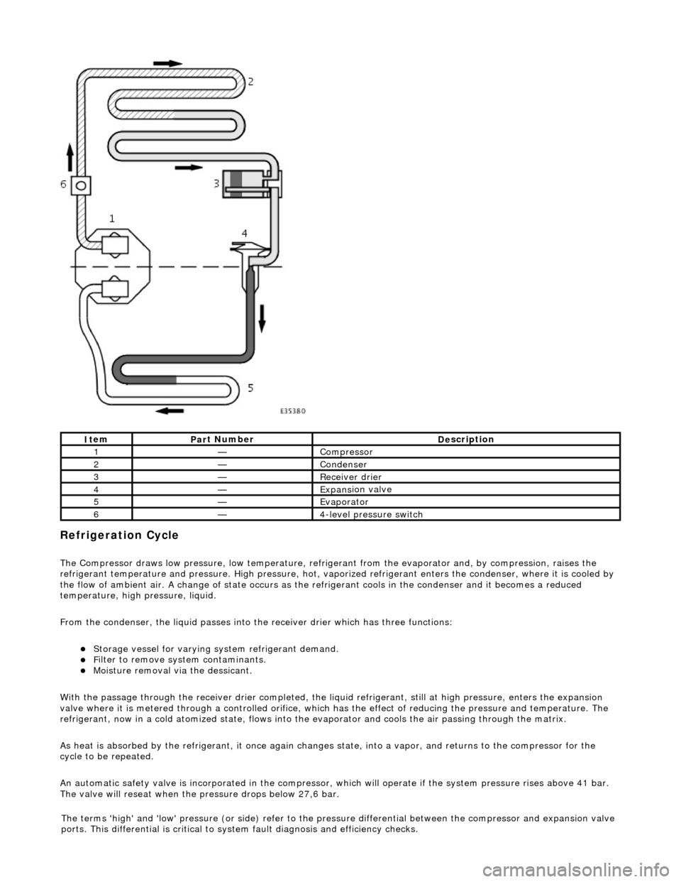
Refrigeration Cycle
The Compressor draws low pressure, lo
w te
mperature, refrigerant from the evaporat or and, by compression, raises the
refrigerant temperature and pressure. High pressure, hot, vaporized refr igerant enters the condenser, where it is cooled by
the flow of ambient air. A change of state occurs as the refrigerant cools in the condense r and it becomes a reduced
temperature, high pressure, liquid.
From the condenser, the liquid passes into the receiver drier which has three functions:
Storage vessel
for varying sy
stem refrigerant demand.
F
ilter to remove sy
stem contaminants.
Mo
isture removal via the dessicant.
With the passage through the receiver drie r completed, the liquid refrigerant, still at high pressure, enters the expansion
valve where it is metered through a contro lled orifice, which has the effect of reducing the pres sure and temperature. The
refrigerant, now in a cold atomized st ate, flows into the evaporator and cools the air passing through the matrix.
As heat is absorbed by the refrigerant, it once again changes state, into a vapor, and returns to the compressor for the
cycle to be repeated.
An automatic safety valve is incorporated in the compressor, which will operate if the system pressure rises above 41 bar.
The valve will reseat when the pressure drops below 27,6 bar.
It
em
Par
t Number
De
scription
1—Compre
ssor
2—Conden
ser
3—Re
ceiver drier
4—Expans
ion valve
5—Evaporator
6—4
-level pressure switch
The terms 'high' and 'low'
pressure (or si
de) refer to the pres sure differential betw een the compressor and expansion valve
ports. This differential is critical to sy stem fault diagnosis and efficiency checks.
Page 1855 of 2490
The In
strument Cluster is the primary electronic control module for the speedomete
r, tachometer, coolant temperature, fuel
level, driver information (Message Centre) and warning lamps.
The Instrument Cluster also:
- provides input / output informatio n signals for use by other modules.
- acts as a protocol converter (software language translator - the languages used on each network are very similar, but
neither can be directly interp reted by the opposite system) for communication between all modules on both the CAN and
SCP multiplexed networks. The Instrument Cluster is the only module on the vehicle which communicates between the two
networks.
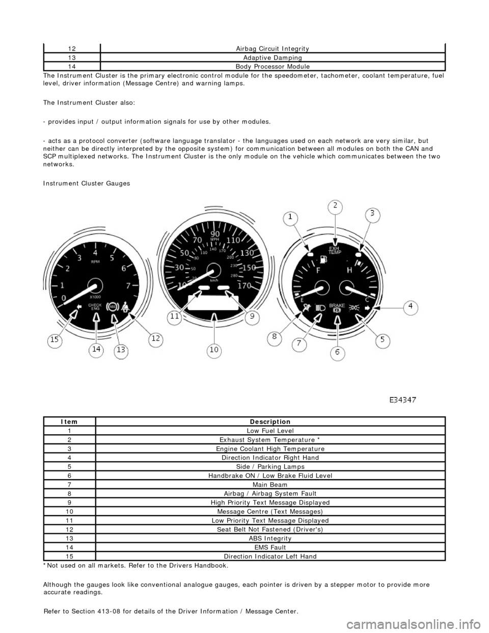
Instrument Cluster Gauges
*Not used on all markets. Refer to the Drivers Handbook.
Although the gauges look like conventional analogue gauges, each pointer is driven by a stepper motor to provide more
12Ai
rbag Circuit Integrity
13Adaptive Damping
14Body Processor
Module
It
em
De
scription
1Low Fu
el Level
2Exhaus
t System Temperature *
3E
ngine Coolant High Temperature
4Di
rection Indicator Right Hand
5Side
/ Parking Lamps
6Handbrake ON / Low
Bra
ke Fluid Level
7Main
Beam
8Ai
rbag / Airbag System Fault
9Hi
gh Priority Text
Message Displayed
10M
essage Centre (Text Messages)
11Low Pri
ority Text Message Displayed
12Se
at Belt Not Fa
stened (Driver's)
13ABS Integrity
14EMS Fault
15D
irection Indicator Left Hand
accu
rate readings.
Refer to Section 413-08 for details of the Driver Information / Message Center.
Page 1975 of 2490
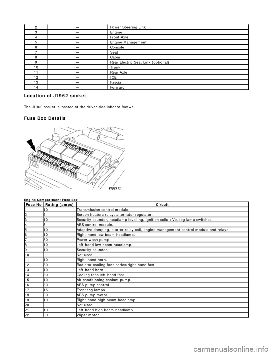
Location of J1962 socket
The J1962 socket is located at the driver side inboard footwell.
Fuse Box Details
Engine Compartment Fuse Box
2—Power Steering Link
3—Engine
4—Front Axle
5—Engine Management
6—Console
7—Seat
8—Cabin
9—Rear Electric Seat Link (optional)
10—Trunk
11—Rear Axle
12—ICE
13—Fascia
14—Forward
Fuse NoRating (amps)Circuit
110Transmission control module.
25Screen heaters relay, alternator regulator.
310Security sounder, headlamp levelling, ignition coils +Ve, fog lamp switches.
45ABS control module.
510Adaptive damping, starter relay coil, engine management control module and relays.
610Right-hand low beam headlamp.
730Power wash pump.
810Left-hand low beam headlamp.
910Security sounder.
10-Not used.
1110Right-hand horn.
1230Radiator cooling fans series/right-hand fast.
1310Left-hand horn
1430Cooling fans left-hand fast.
1510Air conditioning coolant pump.
1630ABS pump control.
1715Front fog lamps.
1830ABS pump motor.
1910Right-hand high beam headlamp.
20-Not used.
2110Left-hand high beam headlamp.
2230Wiper motor.
Page 1989 of 2490

Wiring Harnesses - Wiring Harness
Description and Operation
Introduction
CAUTION: Do not use any other heat shrink sleeve other than the approved glue lined heat shrink sleeve mentioned
in the repair procedure.
The purpose of this document is to promote quick and efficient minor repair to harness connectors or cables using approved
methods and the wiring harness repair kit. Repairs may only be made to cables and connectors which have been
mechanically, not electrically damaged. It also applies wher e the whole extent of the damage can be clearly identified and
rectified.
Care and neatness are essential requir ements in making a perfect repair.
Caution:
At the time of this first issue of the Harness Repair Guide, do not approve re pairs to any of the following circuits:
Any media orientated system transport network harnesses. Supplement restraint system (SRS) firing circuits (Air bags). Link lead assembles, which are unique to safety critical circuits such as anti-lock brake system (ABS) and
thermocouple circuits. An example of this is the ABS wheel speed sensors with moulded connectors.
4. Screened cables, leads and wiring harness(s).
If any harness(s) with defective electrical connector te rminals or wires from the above circuits are a concern,
new components must be installed.
Repair Kit
CAUTION: Where the repair procedure indica tes that a glue lined heat shrink sleeve should be applied, apply sufficient
heat to the glue lined heat shrink to melt the glue in order to provide a water tight seal. Do not over heat the glue lined
heat shrink sleeve so that the wiring harness insulation becomes damaged.
The wiring harness repair kit has been produced which comprises:
Pre-terminated wiring harness(s) of different sizes and types Three sizes of butt splice connectors A selection of colored cable identification sleeves Two sizes of glue lined heat shrink sleeves Crimping pliers A wire cutter and insulation stripper An electrical connector terminal extraction handle and tips
A suitable heat source, fo r shrinking heat shrink sleeves will be required.
The pre-insulated diamond grip range of el ectrical connector terminals and in-line, butt splice connectors contained within
the wiring harness repair kit are the only acceptable product for the repairs of wi ring harnesses. The butt connectors not
only grip the wire but also the insu lation, making a very secure joint.
If an electrical connector terminal is not included in the wiring harness repair kit then approval for the repair is NOT given
and in these circumstances a new wi ring harness must be installed.
Pre-Terminated Wiring Harness( s) and Butt Splice Connectors
All pre-terminated wiring harness(s) and butt splice connectors in the wiring harness repair kit are contained in bags which
can be resealed after use. Each bag is marked with the part number of the items stored within the bag. Each storage
compartment in the wiring harness repair kit is identified with the corresponding part number. Make sure that pre-
terminated wiring harness(s) and connectors are not mixed up it is advisable to only open one bag at a time and to reseal
Page 2012 of 2490
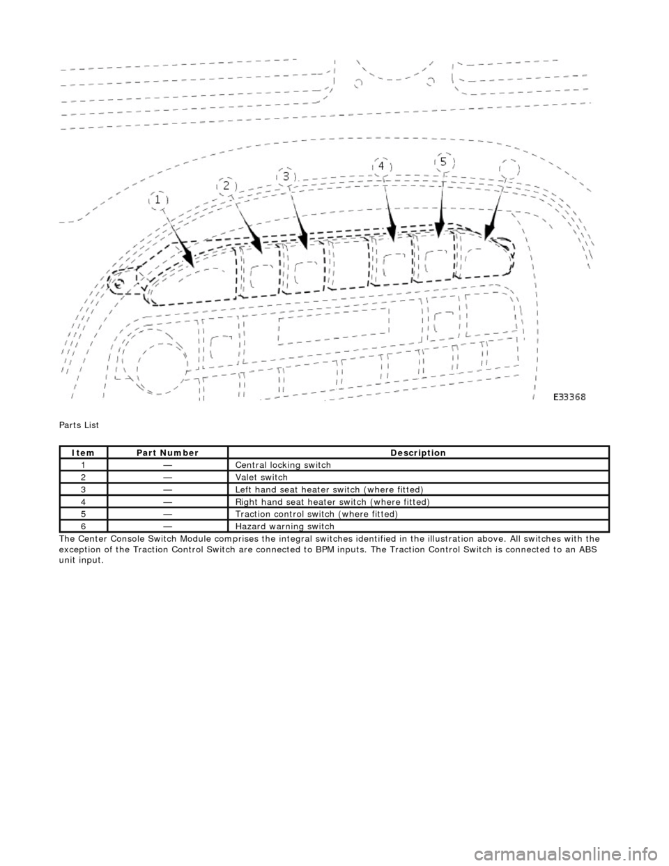
Parts List
The Center Console Switch Module comprises the integral switches identified in the illustration above. All switches with the
exception of the Traction Control Switch are connected to BPM inputs. The Traction Control Switch is connected to an ABS
unit input.
ItemPart NumberDescription
1—Central locking switch
2—Valet switch
3—Left hand seat heater switch (where fitted)
4—Right hand seat heater switch (where fitted)
5—Traction control switch (where fitted)
6—Hazard warning switch
Page 2023 of 2490
sliding roof finisher and clips. Carpet covered trims line the trunk and are secured by fir tree fasteners to the sides and fro nt inner panel.
Rear View Mirrors
The.interior rear view mirror is an electrochromic unit that automatically da rkens to prevent glare from following vehicle
lights. This automatic function is selected by pressing the switch at the bottom of the mirror. Pressing the switch again
cancels this function. An LED then illuminates when automatic dipping is operative. The light sensing unit for the Night
Sentinel automatic lamp operating system is also incorporated in the mirror casing.
The door mirrors are cheater mounted, colo r-keyed units, remote electrically adjustable and heated. Adjustment of both
mirrors is carried out from the driver's door switchpack.A slider switch selects the mirror to be adjusted, and a disc switch
adjusts the selected mirror to the required position. Mirror ad justment can only be made when the ignition switch is in
position I or II or the driver's door is open, and the selector switch is moved from the central position. The door mirrors also
automatically darken under control of the electrochromic interior rear view mirror. Mirror heating elements operate on
selection of backlight heating.
Automatic dipping of passenger door mirror for kerb view when reversing, is fitted as part of the memory pack. With the
ignition switch in position II, the mirror selector switch in the left or right position and reverse gear selected, automatic
dipping is initiated by moving the mirror toggle switch rearwards and releasing. On receipt of the dip signal, the passenger
door mirror is driven downwards either 7 degrees, bottom of travel, or 4,5 to 5,5 seconds, whichever occurs first.
Subsequent rearward movement of the toggle switch achieves further dipping of the mirror in the same increments and
sequence. The mirror can be manu ally returned to the normal memorised positi on by moving the toggle switch forward with
reverse gear selected. The mirror will auto matically return to memorised position on deselection of reverse gear, or moving
ignition switch from position II.
Door mirror fold-back where fitted, to facilitate parking in conf ined spaces, can be initiated when the ignition switch is in
position I or II, the mirror selector switch is in the centra l position and vehicle speed is below 19 km/h (12 mph). Mirror
fold-back is then initiated by moving the toggle switch rear wards and releasing it. The door mirrors are returned to the
normal driving position by agai n moving toggle switch rearwards. There is no speed constraint on this operation. In the
event of a fold-back mirror becoming 'out of position' due to acci dental impact, it must only be re-positioned by initiating
the fold-back sequence.
Loss of power supplies will result in loss of mirror fold-back memory. In the event of such a memory loss with mirrors in the
normal position, fold-back will operate on second movement of the toggle swit ch. On loss of memory with mirrors in the
fold-back position, they will return to the no rmal position on next fold-back operation.
Bumpers
Each bumper comprises a beam mounted to the body via two strut assemblies, and a moulded polypropylene cover
incorporating side armatures and chrome plated blades. Each strut is secured to the BIW by three bolts and supports the
beam on a single bolt/height adjuster. The front bumper cover which is moulded to form a lo wer air intake for the cooling
pack, also incorporates left and right handed twin fog lamps, brake coolin g ducts. Side marker lamps fitted for some
markets serve only as reflectors for UK and Europe. A plastic undertray secured to the lower edge of the front bumper,
improves airflow and minimises the ingres s of road grime in that area. Standard bumpers have glass mat thermoplastic
(GMT) beams mounted on GMT struts. For certain markets, aluminium bumper beams are installed on menasco energy
absorbing struts. Whilst both types of front bumper provide a fu lly integrated 'soft front end' that satisfies bumper impact
requirements, the energy absorbing front and rear bumpers are further designed to withstand 5mph (8kph) impacts with no
visible damage sustained. Side markers/re flectors, and direction indicators are designed for ease of ac cess from the outside
of the bumper. For adjustment and bulb change, the fog lamps are accessed from th e bumper interior. The bumper covers
are body coloured and matched. Replacement covers are supplied complete with side armatures and are finished in primer
Trunk
The trunk houses the spare wheel, the battery, an electrical carrier containing electrical fuses, relays and modules and a
compact disc auto-changer attached to body bracketry. The trun k is fitted with push-fit liners to the sides and front inner
panel.The carpet covered floor is in two removable sections, one covering the spare wheel and wheel changing equipment,
the other covering the battery and electrical carrier. The front and rear edges of the floor board loca te in blocks on the fuel
tank backboard and the rear of the body , which provide two height settings to accommodate the difference in thickness
between the space saver and full sized spare wheels. A moulded finisher covering the rear of the trunk below the sill is
secured to the rear panel by tabs and fir tree fasteners. Finisher panels fitted over the rear lamp units provide for access
from the trunk. Finisher panels fitted to the rear lamp units provide trunk inte rior access to the lamps. The trunk lid
underside is fitted with a removable mo ulded liner and two trunk illumination light s. Trunk locking is based on a central
latch and striker, operated electrically through the central lo cking system by an adjacent actuator or by key in a barrel lock
Page 2040 of 2490
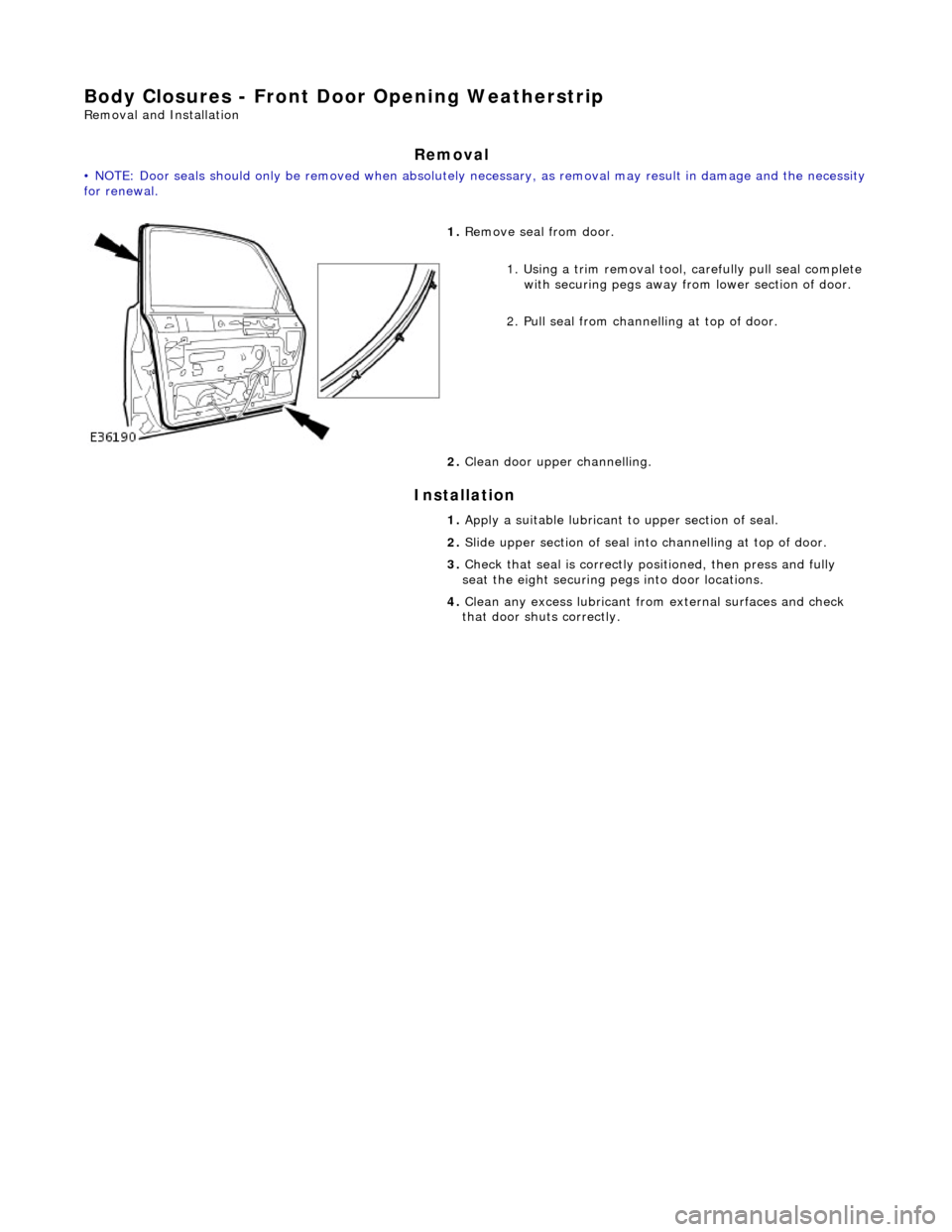
Body Closures - Front Door Opening Weatherstrip
Removal and Installation
Removal
• NOTE: Door seals should only be remove d when absolutely necessary, as removal may result in damage and the necessity for renewal.
Installation
1. Remove seal from door.
1. Using a trim removal tool, carefully pull seal complete
with securing pegs away from lower section of door.
2. Pull seal from chan nelling at top of door.
2. Clean door uppe r channelling.
1. Apply a suitable lubricant to upper section of seal.
2. Slide upper section of seal into channelling at top of door.
3. Check that seal is correctly positioned, then press and fully
seat the eight securing pegs into door locations.
4. Clean any excess lubricant from external surfaces and check
that door shuts correctly.