1998 JAGUAR X308 engine coolant
[x] Cancel search: engine coolantPage 1195 of 2490
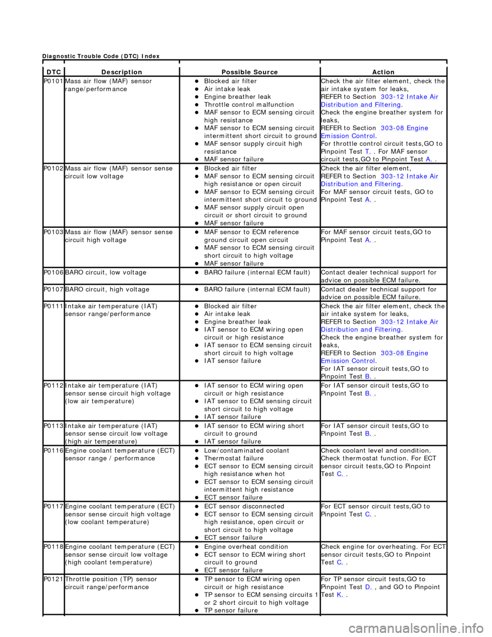
DT
C
De
scription
Possib
le Source
Acti
on
P0101Mass ai
r flow (MAF) sensor
range/performance
Bl
ocked air filter
Air
intake leak
Engine
breather leak
Throttl
e control malfunction
MAF
sensor to ECM sensing circuit
high resistance
MAF
sensor to ECM sensing circuit
intermittent short circuit to ground
MAF
sensor supply circuit high
resistance
MAF
sensor failure
Chec
k the air filter element, check the
air intake system for leaks,
REFER to Section 303
-1
2 Intake Air
Distribu
tion and Filtering
.
Chec
k the engine breather system for
leaks,
REFER to Section 303
-08
Engine
Emissi
on Control
.
F
or throttle control circuit tests,GO to
Pinpoint Test T.
. Fo
r MAF sensor
circuit tests,GO to Pinpoint Test A.
.
P0102Mass ai
r flow (MAF) sensor sense
circuit low voltage
Bl
ocked air filter
MAF
sensor to ECM sensing circuit
high resistance or open circuit
MAF
sensor to ECM sensing circuit
intermittent short circuit to ground
MAF
sensor supply circuit open
circuit or short circuit to ground
MAF
sensor failure
Chec
k the air filter element,
REFER to Section 303
-1
2 Intake Air
Distribu
tion and Filtering
.
For MAF
sensor circuit tests, GO to
Pinpoint Test A.
.
P0103Mass ai
r flow (MAF) sensor sense
circuit high voltage
MAF
sensor to ECM reference
ground circuit open circuit
MAF
sensor to ECM sensing circuit
short circuit to high voltage
MAF sensor
failure
For MAF
sensor circuit tests,GO to
Pinpoint Test A.
.
P0106BARO ci
rcuit, low voltage
BARO f
ailure (internal ECM fault)
Contact deal
er technical support for
advice on possible ECM failure.
P0107BARO ci
rcuit, high voltage
BARO f
ailure (internal ECM fault)
Contact deal
er technical support for
advice on possible ECM failure.
P0111In
take air temperature (IAT)
sensor range/performance
Bl
ocked air filter
Air
intake leak
Engine
breather leak
IAT sensor to
ECM wiring open
circuit or high resistance
IAT se
nsor to ECM sensing circuit
short circuit to high voltage
IAT sensor fail
ure
Chec
k the air filter element, check the
air intake system for leaks,
REFER to Section 303
-1
2 Intake Air
Distribu
tion and Filtering
.
Chec
k the engine breather system for
leaks,
REFER to Section 303
-08
Engine
Emissi
on Control
.
F
or IAT sensor circuit tests,GO to
Pinpoint Test B.
.
P0112In
take air temperature (IAT)
sensor sense circuit high voltage
(low air temperature)
IAT sensor to
ECM wiring open
circuit or high resistance
IAT se
nsor to ECM sensing circuit
short circuit to high voltage
IAT sensor fail
ure
F
or IAT sensor circuit tests,GO to
Pinpoint Test B.
.
P0113In
take air temperature (IAT)
sensor sense circuit low voltage
(high air temperature)
IAT sensor to
ECM wiring short
circuit to ground
IAT sensor fail
ure
F
or IAT sensor circuit tests,GO to
Pinpoint Test B.
.
P0116E
ngine coolant temperature (ECT)
sensor range / performance
Low/contaminated coolant Therm
ostat failure
ECT se
nsor to ECM sensing circuit
high resistance when hot
ECT se
nsor to ECM sensing circuit
intermittent high resistance
ECT sensor
failure
Che
ck coolant level and condition.
Check thermostat function. For ECT
sensor circuit tests,GO to Pinpoint
Test C.
.
P0117E
ngine coolant temperature (ECT)
sensor sense circuit high voltage
(low coolant temperature)
ECT se
nsor disconnected
ECT se
nsor to ECM sensing circuit
high resistance, open circuit or
short circuit to high voltage
ECT sensor
failure
F
or ECT sensor circuit tests,GO to
Pinpoint Test C.
.
P0118E
ngine coolant temperature (ECT)
sensor sense circuit low voltage
(high coolant temperature)
Engine
overheat condition
ECT se
nsor to ECM wiring short
circuit to ground
ECT sensor
failure
Chec
k engine for overheating. For ECT
sensor circuit tests,GO to Pinpoint
Test C.
.
P0121Thro
ttle position (TP) sensor
circuit rang e/performance
TP sensor
to ECM wiring open
circuit or high resistance
TP se
nsor to ECM sensing circuits 1
or 2 short circuit to high voltage
TP sensor
failure
F
or TP sensor circ
uit tests,GO to
Pinpoint Test D.
, and G
O to Pinpoint
Test K.
.
D
iagnostic Trouble Code (DTC) Index
Page 1196 of 2490
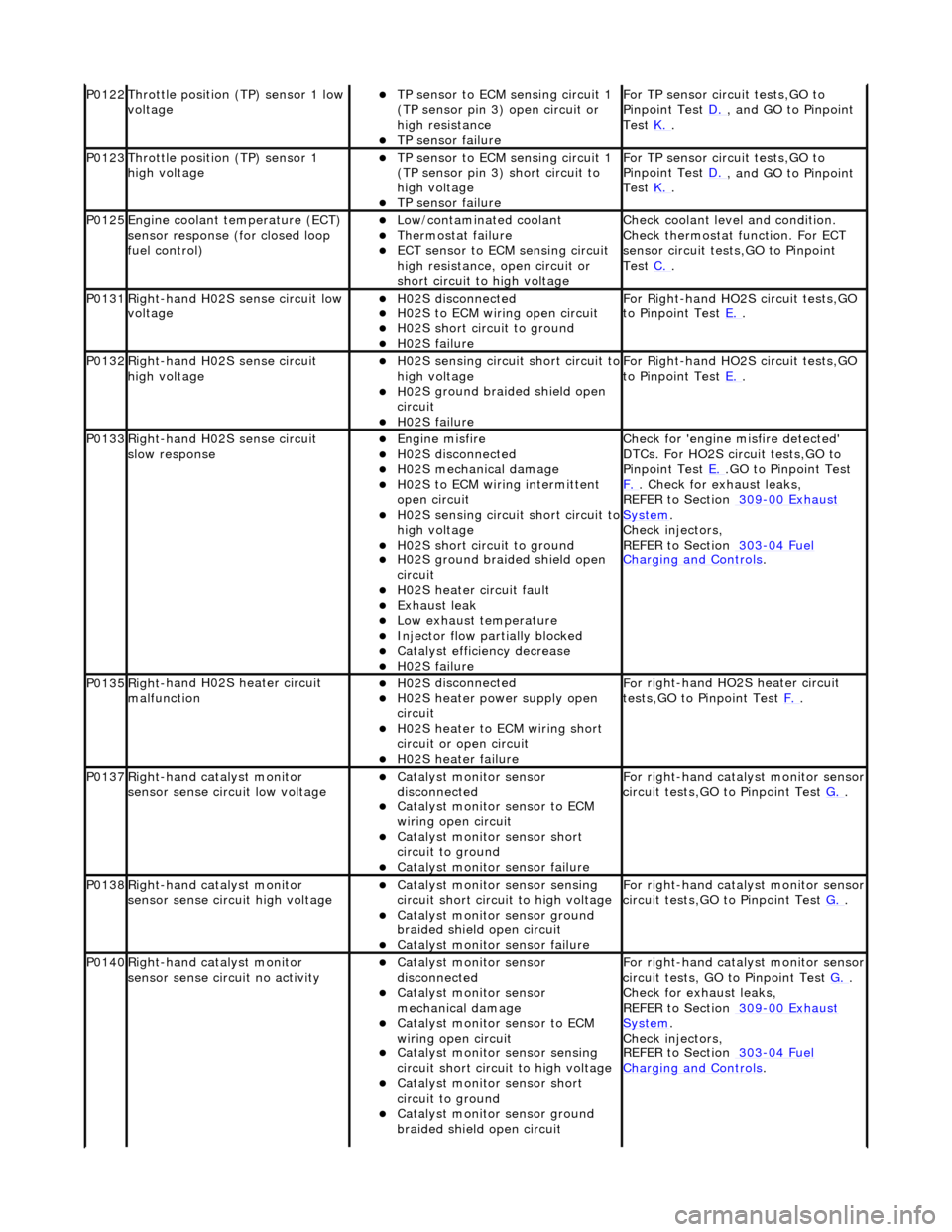
P0122Throttle
position (TP) sensor 1 low
voltage
TP se ns
or to ECM sensing circuit 1
(TP sensor pin 3) open circuit or
high resistance
TP sensor fail
ure
F
o
r TP sensor circ
uit tests,GO to
Pinpoint Test D.
, and GO
to Pinpoint
Test K.
.
P0123Throttl e
position (TP) sensor 1
high voltage
TP se ns
or to ECM sensing circuit 1
(TP sensor pin 3) short circuit to
high voltage
TP sensor fail
ure
F
o
r TP sensor circ
uit tests,GO to
Pinpoint Test D.
, and GO
to Pinpoint
Test K.
.
P0125En
gine coolant temperature (ECT)
sensor response (for closed loop
fuel control)
Low/contaminated coolant Therm o
stat failure
ECT se
ns
or to ECM sensing circuit
high resistance, open circuit or
short circuit to high voltage
Che c
k coolant level and condition.
Check thermostat function. For ECT
sensor circuit tests,GO to Pinpoint
Test C.
.
P0131Right -
hand H02S sense circuit low
voltage
H02 S
disconnected
H0
2S to
ECM wiring open circuit
H0
2S short ci
rcuit to ground
H0
2S fail
ure
F
or R
ight-hand HO2S circuit tests,GO
to Pinpoint Test E.
.
P0132Right-
hand H02S sense circuit
high voltage
H02 S
sensing circuit short circuit to
high voltage
H0 2S groun
d braided shield open
circuit
H0 2S fail
ure
F
or R
ight-hand HO2S circuit tests,GO
to Pinpoint Test E.
.
P0133Right-
hand H02S sense circuit
slow response
Engine m
isfire
H02
S
disconnected
H0
2S mechanical damage
H0
2S to
ECM wiring intermittent
open circuit
H02 S
sensing circuit short circuit to
high voltage
H02S short ci
rcuit to ground
H02S groun
d braided shield open
circuit
H0 2S heater circuit faul
t
Exhaus
t leak
Low e
x
haust temperature
Injector fl
ow parti
ally blocked
Catal
y
st efficiency decrease
H0
2S fail
ure
Chec
k for 'en
gine misfire detected'
DTCs. For HO2S circuit tests,GO to
Pinpoint Test E.
.G
O to Pinpoint Test
F.
. Check for exhaust leaks,
REF
ER to Section 309
-00
Ex
haust
Sy
ste
m
.
Chec k inje
ctors,
REFER to Section 303
-04 Fu
el
Charging and Cont
rols
.
P0135Right
-
hand H02S heater circuit
malfunction
H02 S
disconnected
H0
2S h
eater power supply open
circuit
H0 2S heater to ECM wi
ring short
circuit or open circuit
H0 2S heater fai
lure
F
o
r right-hand HO2S heater circuit
tests,GO to Pinpoint Test F.
.
P0137Right-
hand catalyst monitor
sensor sense circuit low voltage
Catal y
st monitor sensor
disconnected
Catal y
st monitor sensor to ECM
wiring open circuit
Catal y
st monitor sensor short
circuit to ground
Cat a
lyst monitor sensor failure
F
or ri
ght-hand catalyst monitor sensor
circuit tests,GO to Pinpoint Test G.
.
P0138Right -
hand catalyst monitor
sensor sense circuit high voltage
Catal y
st monitor sensor sensing
circuit short circuit to high voltage
Catalyst
monitor sensor ground
braided shield open circuit
Cata
lyst monitor sensor failure
F
or ri
ght-hand catalyst monitor sensor
circuit tests,GO to Pinpoint Test G.
.
P0140Right -
hand catalyst monitor
sensor sense circuit no activity
Catal y
st monitor sensor
disconnected
Catal y
st monitor sensor
mechanical damage
Catal y
st monitor sensor to ECM
wiring open circuit
Catal y
st monitor sensor sensing
circuit short circuit to high voltage
Cataly
st monitor sensor short
circuit to ground
Catalyst
monitor sensor ground
braided shield open circuit
F or ri
ght-hand catalyst monitor sensor
circuit tests, GO to Pinpoint Test G.
.
Check f o
r exhaust leaks,
REFER to Section 309
-00 Ex
haust
Sy
ste
m
.
Chec k inje
ctors,
REFER to Section 303
-04 Fu
el
Charging and Con
t
rols
.
Page 1206 of 2490
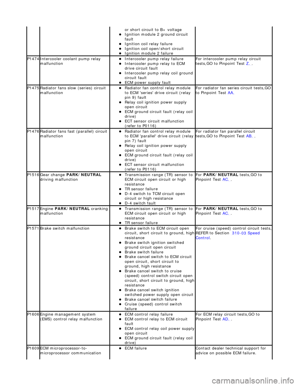
or sho
rt circuit to B+ voltage
Ignition modul
e
2 ground circuit
fault
Ignition coil relay fai
lure
Ignition coil
open/short
circuit
Ignition modul
e
2 failure
P1474Int
e
rcooler coolant pump relay
malfunction
Intercooler pump relay failure
Intercooler pump relay
to ECM
drive circuit fault
Intercooler pump relay coi
l ground
circuit fault
ECM power supply f
ault
F
or i
ntercooler pump relay circuit
tests,GO to Pinpoint Test Z.
.
P1475Ra
diator fans slow
(series) circuit
malfunction
R a
diator fan control relay module
to ECM 'series' drive circuit (relay
pin 9) fault
Relay coil ignition power supply
o p
en circuit
ECM ground circuit fault (relay coil
drive)
ECT se ns
or circuit malfunction
(refer to P0116)
F o
r radiator fan seri
es circuit tests,GO
to Pinpoint Test AA.
P1476Ra
diator fans fast (parallel) circuit
malfunction
R a
diator fan control relay module
to ECM 'parallel' drive circuit (relay
pin 7) fault
Relay coil ignition power supply
o p
en circuit
ECM ground circuit faul
t (relay coil
drive)
ECT sens
or circuit malfunction
(refer to P0116)
F or radi
ator fan parallel circuit
tests,GO to Pinpoint Test AB.
.
P1516Gear change PARK
/NEUTRAL
driving malfunction
Transmission range (T
R) sensor to
ECM circuit open circuit or high
resistance
TR sensor f
ailure
D-
4
switch to TCM circuit open
circuit or high resistance
D-4 swi
tch fault
For
PARK/NEUTRAL tests,GO to
Pinpoint Test AC.
.
P1517Engine PA
RK/NEUTRAL
cranking
malfunction
Transmissi on range (T
R) sensor to
ECM circuit open circuit or high
resistance
TR sensor f
ailure
Fo
r
PARK/NEUTRAL tests,GO to
Pinpoint Test AC.
.
P1571Brake swit
ch malfunction
Brake sw
it
ch to ECM circuit open
circuit, short circ uit to ground, high
resistance
Brake sw it
ch ignition switched
ground circuit open circuit
Brake sw it
ch failure
Brake ca
ncel
switch to ECM circuit
open circuit, short circuit to
ground, high resistance
Brake ca nce
l switch to cruise
(speed) control switch circuit open
circuit, short circ uit to ground, high
resistance
Brake cance
l switch ignition
switched power supply open circuit
Brake ca nce
l switch failure
Cru
i
se (speed) control switch
failure
For cru i
se (speed) control circuit tests,
REF
E
R to Section 310
-03
Sp
eed
Control.
P1606Engine
m
anagement system
(EMS) control relay malfunction
ECM co ntrol rel
ay failure
ECM c
o
ntrol relay to ECM circuit
fault
ECM co ntrol rel
ay coil power supply
open circuit
ECM ground circuit faul t (relay coil
drive)
F or ECM
relay circuit tests,GO to
Pinpoint Test AD.
.
P1609EC
M microprocessor-to-
microprocessor communication
ECM failu r
e
Contact deal
er techni
cal support for
advice on possible ECM failure.
Page 1209 of 2490
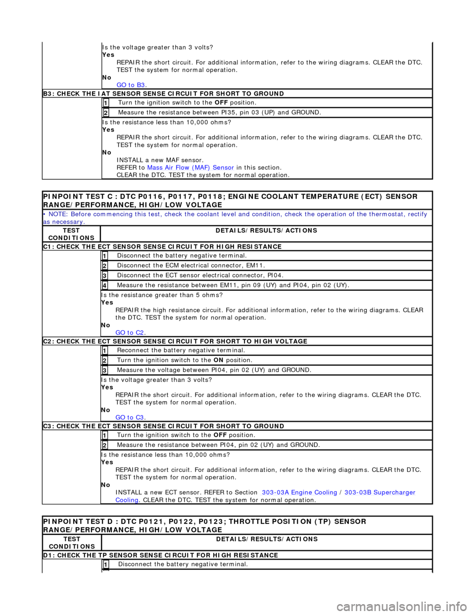
Is th
e voltage greater than 3 volts?
Yes REPAIR the short circuit. For addi tional information, refer to the wiring diagrams. CLEAR the DTC.
TEST the system for normal operation.
No GO to B3
.
B3: CHECK
THE IAT SENSOR SENS
E CIRCUIT FOR SHORT TO GROUND
Turn the ignition swi
tch to the OFF
position.
1
Meas
ure the resistance between PI35, pin 03 (UP) and GROUND.
2
Is
the resistance less than 10,000 ohms?
Yes
REPAIR the short circuit. For addi tional information, refer to the wiring diagrams. CLEAR the DTC.
TEST the system for normal operation.
No INSTALL a new MAF sensor.
REFER to Mass Air Flow (MAF) Sensor
in this section.
CLEAR the DTC. TEST the system for normal operation.
PI
NPOINT TEST C : DTC P0116, P0117, P0118
; ENGINE COOLANT TEMPERATURE (ECT) SENSOR
RANGE/PERFORMANCE, HIGH/LOW VOLTAGE
•
NOTE: Before commencing this
test, check the coolant level and condition, check the operation of the thermostat, rectify
as necessary.
TE
ST
CONDITIONS
D
ETAILS/RESULTS/ACTIONS
C1: CHECK THE ECT SEN
SOR SENS
E CIRCUIT FOR HIGH RESISTANCE
Di
sconnect the battery negative terminal.
1
D
isconnect the ECM electrical connector, EM11.
2
D
isconnect the ECT sensor electrical connector, PI04.
3
Meas
ure the resistance between EM11, pin 09 (UY) and PI04, pin 02 (UY).
4
Is th
e resistance greater than 5 ohms?
Yes
REPAIR the high resistance circui t. For additional information, refer to the wiring diagrams. CLEAR
the DTC. TEST the system for normal operation.
No GO to C2
.
C2: CHECK THE ECT SEN
SOR SENSE CI
RCUIT FOR SHORT TO HIGH VOLTAGE
R
econnect the battery negative terminal.
1
Turn the ignition swi
tch to the ON
position.
2
Meas
ure the voltage between PI04, pin 02 (UY) and GROUND.
3
Is th
e voltage greater than 3 volts?
Yes REPAIR the short circuit. For addi tional information, refer to the wiring diagrams. CLEAR the DTC.
TEST the system for normal operation.
No GO to C3
.
C3: CHECK THE ECT SEN
SOR SENSE CIRCUIT FOR SHORT TO GROUND
Turn the ignition swi
tch to the OFF
position.
1
Meas
ure the resistance between PI04, pin 02 (UY) and GROUND.
2
Is
the resistance less than 10,000 ohms?
Yes REPAIR the short circuit. For addi tional information, refer to the wiring diagrams. CLEAR the DTC.
TEST the system for normal operation.
No INSTALL a new ECT sensor. REFER to Section 303
-0
3A Engine Cooling
/
30
3
-0
3B Supercharger
Coo
ling
. CLEA
R the DTC. TEST the sy
stem for normal operation.
P
INPOINT TEST D : DTC P0121, P0122,
P0123; THROTTLE POSITION (TP) SENSOR
RANGE/PERFORMANCE, HIGH/LOW VOLTAGE
TE
ST
CONDITIONS
D
ETAILS/RESULTS/ACTIONS
D1: CHECK
THE TP SENSOR SENS
E CIRCUIT FOR HIGH RESISTANCE
Di
sconnect the battery negative terminal.
1
Page 1233 of 2490
E
lectronic Engine Controls - Ca
mshaft Position (CMP) Sensor
Re
moval and Installation
Remov
al
1.
Disc
onnect battery ground cable (IMPORTANT, see SRO
86.15.19 for further information).
2. Remove engine covers ; refer to 12.30.06.
3. WARNING: BEFORE PROCEEDING, IT IS ESSENTIAL THAT
THE WARNING NOTES GIVEN IN SECTION 100-00 (UNDER THE
HEADING 'SAFETY PRECAUTIONS') ARE READ AND
UNDERSTOOD.
De-pressurize fuel system; refer to 19.50.02.
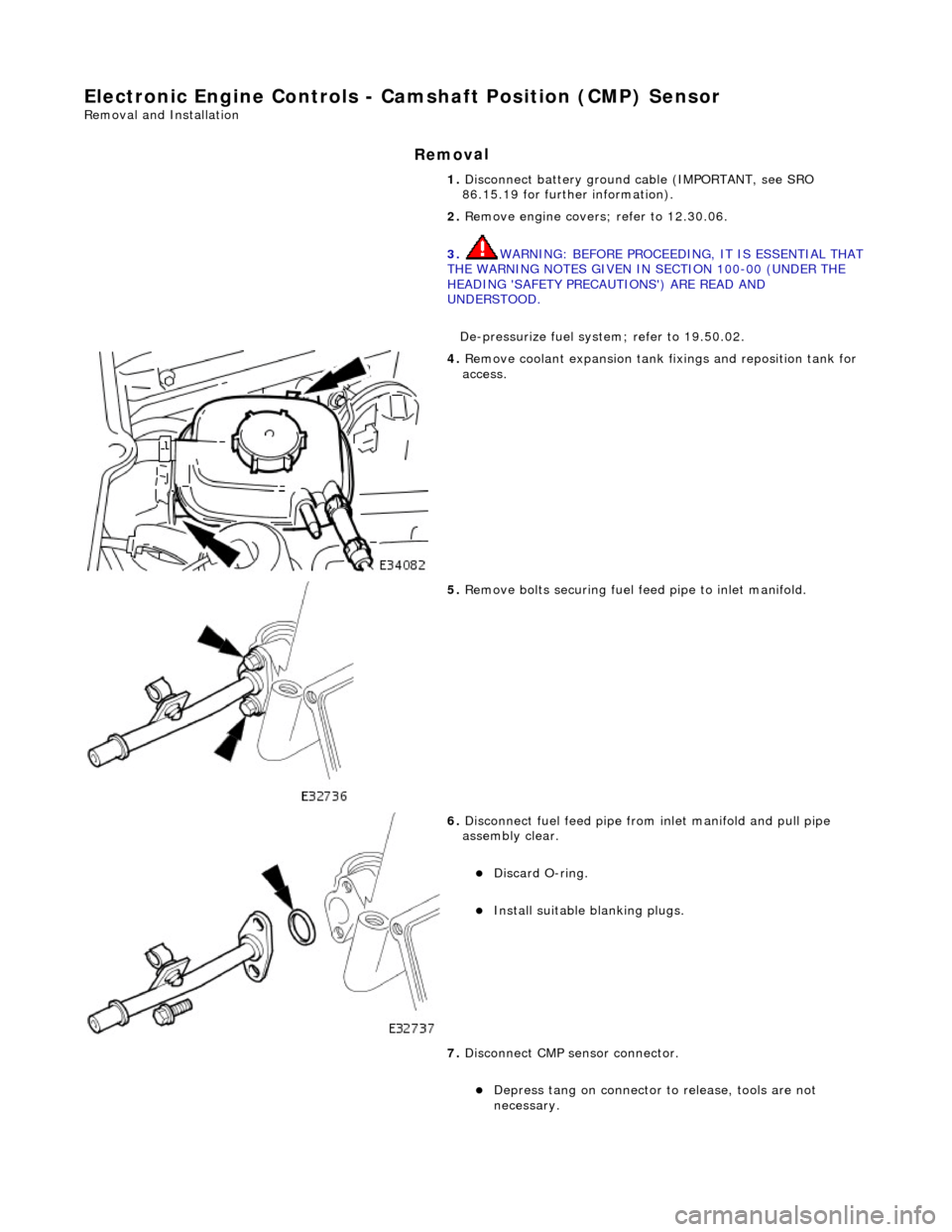
4. R
emove coolant expansion tank fixings and reposition tank for
access.
5. R
emove bolts securing fuel fe
ed pipe to inlet manifold.
6. Di
sconnect fuel feed pipe from inlet manifold and pull pipe
assembly clear.
Di
scard O-ring.
Inst
all suitable blanking plugs.
7. Disconnect CMP sensor connector.
De
press tang on connector to release, tools are not
necessary.
Page 1246 of 2490
El
ectronic Engine Controls - En
gine Coolant Temperature (ECT)
Sensor4.0L NA V8 - AJ 27/3.2L NA V8 - AJ26
Remo
val and Installation
Remova
l
Installation
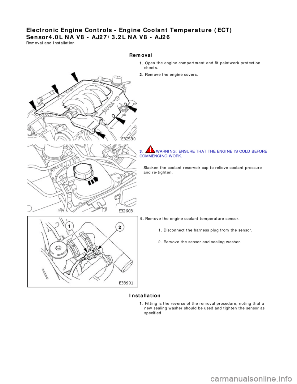
1. Op
en the engine compartment and fit paintwork protection
sheets.
2. Re
move the engine covers.
3. WA
RNING: ENSURE THAT THE ENGINE IS COLD BEFORE
COMMENCING WORK.
Slacken the coolant reservoir ca p to relieve coolant pressure
and re-tighten.
4. Remove t
he engine coolant temperature sensor.
1. Disconnect the harness plug from the sensor.
2. Remove the sensor and sealing washer.
1. Fitting is the reverse of the removal procedure, noting that a
new sealing washer should be us ed and tighten the sensor as
specified
Page 1248 of 2490
El
ectronic Engine Controls - En
gine Coolant Temperature (ECT)
Sensor4.0L SC V8 - AJ26
Re mo
val and Installation
Remova
l
Installation
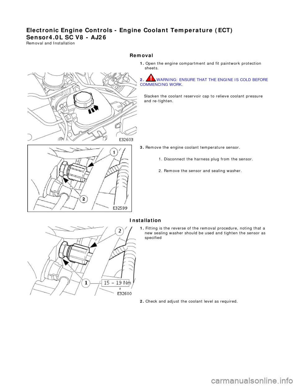
1.
Op
en the engine compartment and fit paintwork protection
sheets.
2. WA
RNING: ENSURE THAT THE ENGINE IS COLD BEFORE
COMMENCING WORK.
Slacken the coolant reservoir ca p to relieve coolant pressure
and re-tighten.
3. Remove t
he engine coolant temperature sensor.
1. Disconnect the harness plug from the sensor.
2. Remove the sensor and sealing washer.
1. Fi
tting is the reverse of the removal procedure, noting that a
new sealing washer should be us ed and tighten the sensor as
specified
2. Check and adjust the cool ant level as required.
Page 1375 of 2490
Automatic Transmission/Transaxle - 4.0L NA V8 - AJ27/3.2L NA V8 - AJ26
- Transmission
Removal
Removal
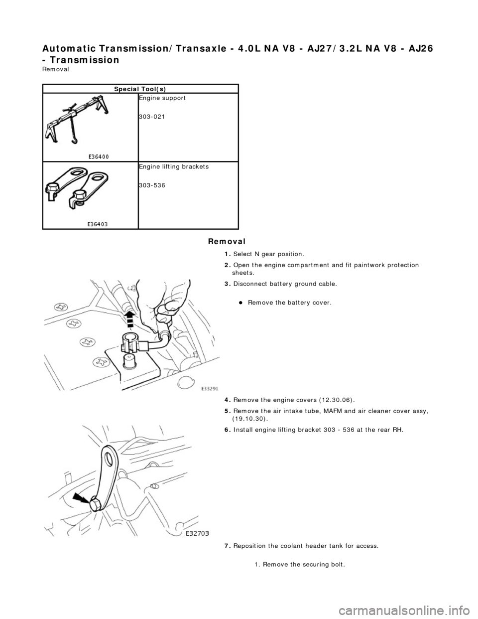
Special Tool(s)
Engine support
303-021
Engine lifting brackets
303-536
1. Select N gear position.
2. Open the engine compartment and fit paintwork protection
sheets.
3. Disconnect battery ground cable.
Remove the battery cover.
4. Remove the engine covers (12.30.06).
5. Remove the air intake tube, MAFM and air cleaner cover assy,
(19.10.30).
6. Install engine lifting bracket 303 - 536 at the rear RH.
7. Reposition the coolant he ader tank for access.
1. Remove the securing bolt.