Page 1128 of 2490

Intake Air Distribution and Filtering - Supercharger
Remo
val and Installation
Remov
a
l
Installation
1. Disc onne
ct battery ground cable (IMPORTANT, see SRO
86.15.19 for further information).
2. Drain radiator coolant; refer to 26.10.01.
3. Remove air cleaner cover / intake assembly; refer to 19.10.30.
4. Remove throttle body; refer to 19.70.04.
5. Remove exhaust gas re-circulation valve (EGR) if installed;
refer to 17.45.01.
6. Remove throttle intake elbo w; refer to (SC) 19.70.28.
7. Remove supercharger outlet duct; refer to 18.50.16.
8. Remove coolant outlet pipe; refe r to operation (SC) 26.31.08.
9. Remove supercharger drive belt; refer to 18.50.08.
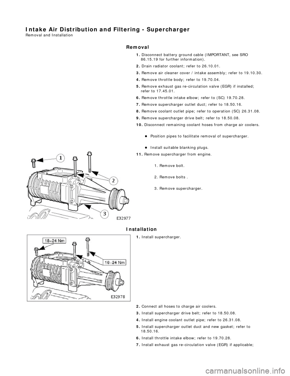
10. Disconnect remaining coolant hoses from charge air coolers.
Position pipes to facilitate removal
of supercharger.
Inst
al
l suitable blanking plugs.
11 .
R
emove supercharger from engine.
1. Remove bolt.
2. Remove bolts .
3. Remove supercharger.
1. Inst al
l supercharger.
2. Connect all hoses to charge air coolers.
3. Install supercharger driv e belt; refer to 18.50.08.
4. Install engine coolant outlet pipe; refer to 26.31.08.
5. Install supercharger outlet du ct and new gasket; refer to
18.50.16.
6. Install throttle intake elbow; refer to 19.70.28.
7. Install exhaust gas re-circulation valve (EGR) if applicable;
Page 1129 of 2490
r
efer to 17.45.01.
8. Install throttle body ; refer to 19.70.04.
9. Install air cleaner cover / intake assembly; refer to19.10.30.
10. Refill cooling system; refer to (SC) (26.10.01).
Page 1134 of 2490

Intake Air Distribution and Filtering - Thrott
le Body Elbow
Re
mo
val and Installation
Remov
a
l
1.
WARNING: B E
FORE PROCEEDING, IT IS ESSENTIAL THAT
WARNING NOTES GIVEN IN SECTION 100-00 (UNDER HEADING
'SAFETY PRECAUTIONS') AR E READ AND UNDERSTOOD.
Disconnect battery ground cable (IMPORTANT, see SRO
86.15.19 for further information).
2. Re
move air cleaner cover / inta
ke assembly; refer 19.10.30.
3. Remove throttle assemb ly; refer to 19.70.04.
4. Remove exhaust gas recirculation (EGR) valve where installed;
refer 17.45.01.
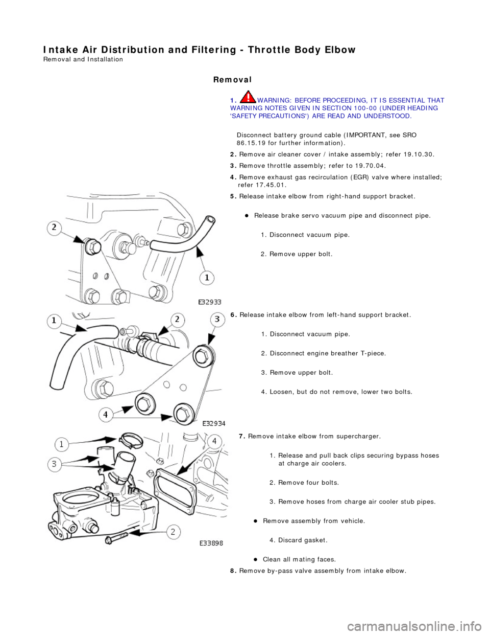
5. Re
lease intake elbow from right-hand support bracket.
Re
lea
se brake servo vacuum pi
pe and disconnect pipe.
1. Disconnect vacuum pipe.
2. Remove upper bolt.
6. Relea
se intake elbow from le
ft-hand support bracket.
1. Disconnect vacuum pipe.
2. Disconnect engine breather T-piece.
3. Remove upper bolt.
4. Loosen, but do not remove, lower two bolts.
7. Re
move intake elbow from supercharger.
1. Release and pull back cl ips securing bypass hoses
at charge air coolers.
2. Remove four bolts.
3. Remove hoses from charge air cooler stub pipes.
Re move as
sembly from vehicle.
4. Discard gasket.
Cle a
n all mating faces.
8. Remove by-pass valve assembly from intake elbow.
Page 1137 of 2490
Intake Air Distribution and Filtering - Throt
tle Body Elbow4.0L NA V8 -
AJ27/3.2L NA V8 - AJ26
Re
moval and Installation
Remov
al
S
pecial Tool(s)
Re
lease tool - quick fit
310-044 (JD 182)
R
elease tool 5 /16 - quick fit
310-054 (JD 203)
1. WARNING: BEFORE PROCEEDING, IT IS ESSENTIAL THAT
THE WARNING NOTES GIVEN IN SECTION 100-00 (UNDER THE
HEADING 'SAFETY PRECAUTIONS') ARE READ AND
UNDERSTOOD.
Disconnect battery ground cable (IMPORTANT, see SRO
86.15.19 for further information).
2. D
epressurize fuel sy
stem; refer to 19.50.02
3. Remove air cleaner cover / intake assembly; refer to 19.10.30.
4. Remove throttle body; refer to 19.70.04.
5. R
elease intake elbow from right-hand support bracket.
Re
lease brake servo vacuum pi
pe and disconnect pipe.
1. Disconnect vacuum pipe.
2. Remove bolt.
6. Release intake elbow from le ft-hand support bracket.
1. Disconnect vacuum pipe.
2. Disconnect engine breather T-piece.
3. Remove bolt.
4. Loosen, but do not remove two bolts.
Page 1145 of 2490
Intake Air Distribution and Filtering - Throt
tle Body Elbow Gasket
Re
moval and Installation
Remov
al
Installation
1.
R
emove throttle intake elbo
w; refer to (SC)19.70.28.
1. Installation is a reversal of the removal procedure.
Page 1147 of 2490
Intake Air Distribution and Filtering - Throt
tle Body Elbow Gasket4.0L SC
V8 - AJ26
Re
moval and Installation
Remov
al
Installation
1.
R
emove throttle intake elbo
w; refer to (SC)19.70.28.
1. Installation is a reversal of the removal procedure.
Page 1161 of 2490

E
vaporative Emissions - Evaporative Emissions
D
iagnosis and Testing
Prelim
inary Inspection
1.
1. Vis
ually inspect for obvious signs of mechanical or electrical damage.
V
isual Inspection Chart
2.
2. If
an obvious cause for an observed or
reported concern is found, correct th e cause (if possible) before proceeding
to the next step.
3. 3. If the concern is not visually evident, verify the symptom and proceed with diagnosis, using the Jaguar approved
diagnostic system, where available.
4. 4. Where K-Line or Vacutec equipment is available, it should be used as an aid to diagnosis. The equipment must be
capable of testing to the 0.020 thou standard (2001 MY on).
Diagnostic Drive Cycles
Following th
e setting of a DTC, the appropriate repairs must
be carried out, and the normal operation of the system
checked. This will be done by performing a series of drive cycles which will enable the vehicle to operate the evaporative
emissions system as a function check. For details of the drive cycles,
REFER to Section 303
-1
4 Electronic Engine Controls
.
ECM adapt
ations.
Diagnostic Trouble Code
(D
TC) index/Symptom Chart
1.
1. Wh
ere the Jaguar approved diagnostic sy
stem is available, complete the S93 report before clearing any or all fault
codes from the vehicle.
• NOTE: If a DTC cannot be cleared, then there is a permanent fault present that flag s again as soon as it is cleared. (The
exception to this is P1260, which will only clear following an ignition OFF/ON cycle after rectification).
2. 2. If the cause is not visually evident and the Jaguar approv ed diagnostic system is not available, use a fault code
reader to retrieve the fault codes be fore proceeding to the Diagnostic Trou ble Code (DTC) Index Chart, or the
Symptom Chart if no DTCs are set.
3. 3. Using the Jaguar approved diagnostic system where available, and a scan tool where not, check the freeze frame
data for information on the conditions applicable when the fault was flagged. The format of this will vary,
depending on the tool used, but can pr ovide information useful to the technician in diagnosing the fault.
CAUTION: When probing connectors to take measurements in the course of the pinpoint tests, use the adaptor kit,
part number 3548-1358-00.
• NOTE: When performing electrical voltag e or resistance tests, always use a digital multimeter (DMM) accurate to 3
decimal places, and with an up-t o-date calibration certificate. When testing resistance, always take the resistance of the
DMM leads into account.
• NOTE: Check and rectify basic faults before beginning diagnostic ro utines involving pinpoint tests.
MechanicalElectrical
Engi
ne oil level
Coo
ling system coolant level
Fue
l level
Fuel contaminatio
n
/grade/quality
Throttle body Poly
-vee belt
F
uses
W
iring harness
E
lectrical connector(s)
Sens
or(s)
Engine
control module (ECM)
Page 1178 of 2490
Throttle Position (TP) Sensor
Location
P
arts List
sen
d
s the ECM a signal indica
ting throttle plate angle
is
the main input to the ECM from the driver
i
s
a dual Hall effect devi
ce mounted on the motor en d of the throttle body
Two additional sensors are attached to the throttle body to provide additional feedback to the ECM: a mechanical guard
position sensor and an accelerator pedal position sensor.
Cam s
haft Position (CMP) Sensor
sen
d
s the ECM a signal indicating camshaft po
sition for fuel synchronization purposes
is
a variable reluctance device mounted on bank 2 cylinder side face
generates a signal when the ri
ng
fitted to the bank 2 inlet
camshaft passes the sensor
Cranksha
ft Position (CKP) Sensor
i
s
a variable reluctance device
mounted on the engine oil pan
Ite
m
Par
t
Number
De
scr
iption
1—Acce
le
rator pedal and mechanic
al guard position sensors
2—Throttle
(blade)
position sensor