1998 JAGUAR X308 Speed Sensor
[x] Cancel search: Speed SensorPage 1271 of 2490
Controller Area Network (CAN)
The TCM is an integral part of the CAN system which facilitates the interchange of real-time data between control modules
and sensors. Please see section 303- 14 for a full description of CAN.
OBDII Interface
Data concerning OBDII related transmission failures is stored in the ECM for access via the J1962 socket.
System Functions
Range Selection
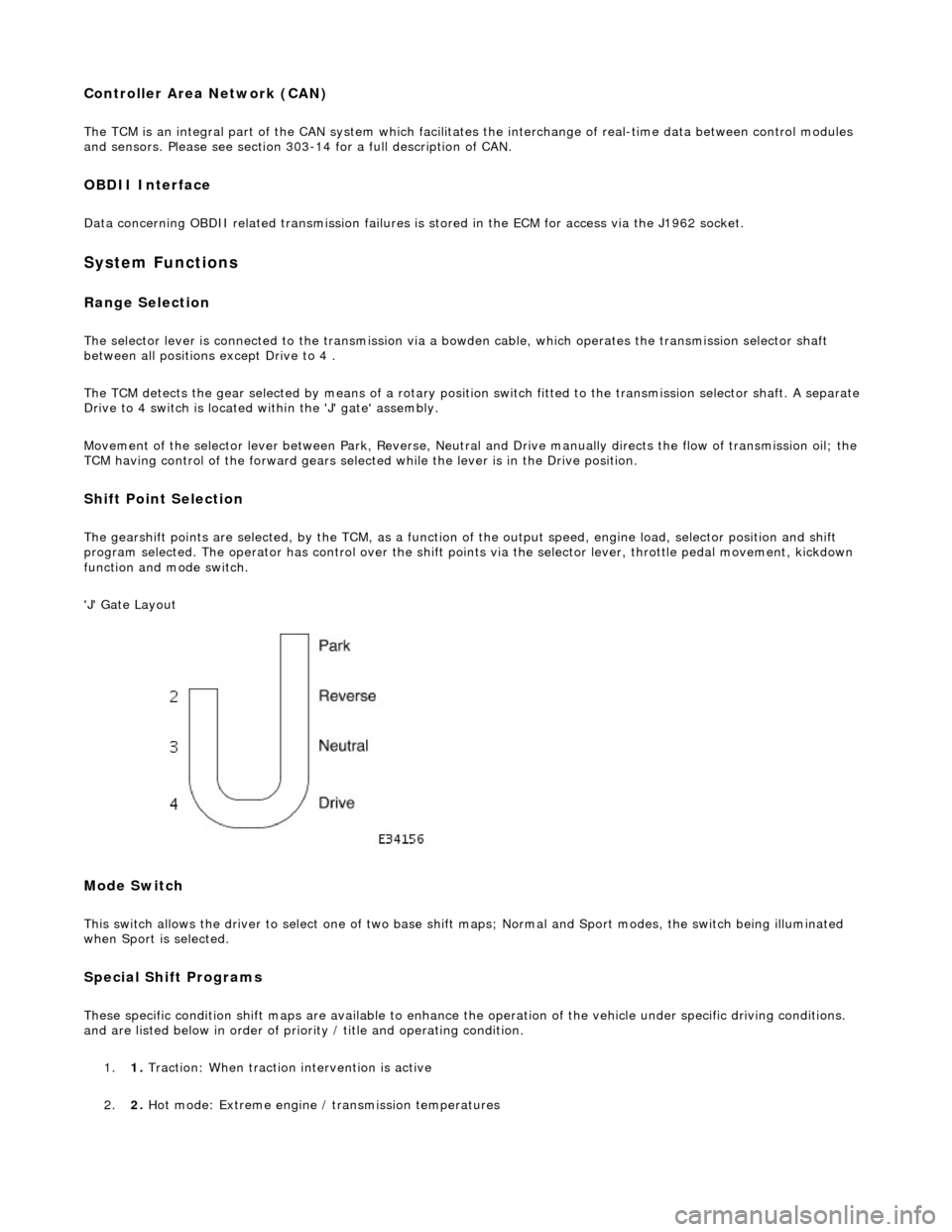
The selector lever is connected to the transmission via a bowden cable, which operates the transmission selector shaft
between all positions except Drive to 4 .
The TCM detects the gear selected by means of a rotary position switch fitted to the transmission selector shaft. A separate
Drive to 4 switch is located within the 'J' gate' assembly.
Movement of the selector lever between Park, Reverse, Neutral and Drive manually directs th e flow of transmission oil; the
TCM having control of the forward gears selected while the lever is in the Drive position.
Shift Point Selection
The gearshift points are selected, by the TCM, as a function of the output speed, engine load, selector position and shift
program selected. The operator has control over the shift points via the selector lever, throttle pedal movement, kickdown
function and mode switch.
'J' Gate Layout
Mode Switch
This switch allows the driver to select one of two base shift maps; Normal and Sport modes, the switch being illuminated
when Sport is selected.
Special Shift Programs
These specific condition shift maps are available to enhance the operation of the vehicle under specific driving conditions.
and are listed below in order of priority / title and operating condition.
1. 1. Traction: When traction intervention is active
2. 2. Hot mode: Extreme engine / transmission temperatures
Page 1272 of 2490
3.3. Gradient: Under specific speeds and loads
4. 4. Cruise: During cruise control
5. 5. Manual: Shift map when the LH side of the 'J gate' is used
Three specific condition shift maps have a higher priority than the two base shift maps and will intervene when appropriate
conditions prevail for traction, gradient or cruise.
When traction control (engine or brake system derived) is operational the TCM will implement the traction map to maximise
control of wheel slip.
The gradient maps are intended to enhance vehicle drivability when towing or climbing a gradient. The TCM will implement
the maps when increased driving resistan ce is detected and enhanced drivability, cooling and increa sed performance is
appropriate.
The cruise map is intended to minimize unwanted gearshifts and 'hunting' and is activated when cruising near to the set
speed, or resuming.
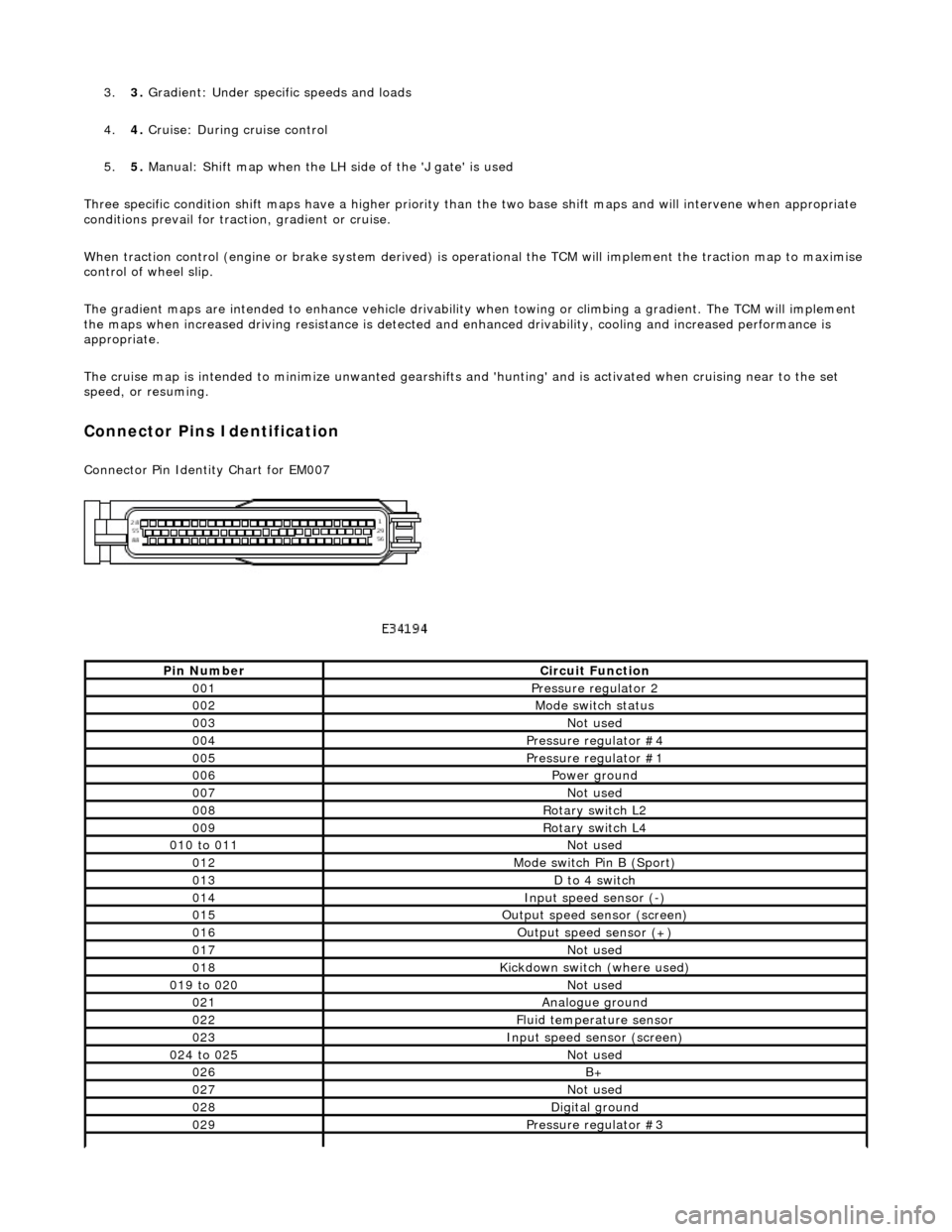
Connector Pins Identification
Connector Pin Identity Chart for EM007
Pin NumberCircuit Function
001Pressure regulator 2
002Mode switch status
003Not used
004Pressure regulator #4
005Pressure regulator #1
006Power ground
007Not used
008Rotary switch L2
009Rotary switch L4
010 to 011Not used
012Mode switch Pin B (Sport)
013D to 4 switch
014Input speed sensor (-)
015Output speed sensor (screen)
016Output speed sensor (+)
017Not used
018Kickdown switch (where used)
019 to 020Not used
021Analogue ground
022Fluid temperature sensor
023Input speed sensor (screen)
024 to 025Not used
026B+
027Not used
028Digital ground
029Pressure regulator #3
Page 1273 of 2490
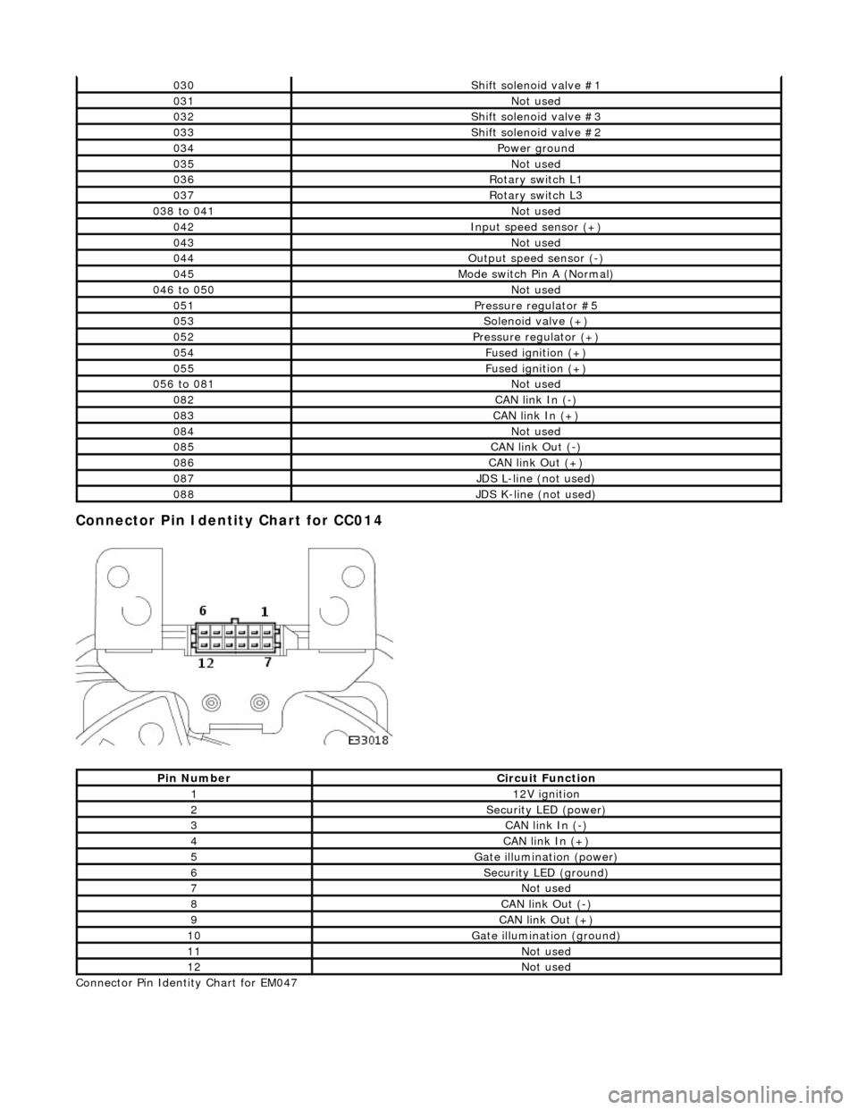
Connector Pin Identity Chart for CC014
Connector Pin Identity Chart for EM047
030Shift solenoid valve #1
031Not used
032Shift solenoid valve #3
033Shift solenoid valve #2
034Power ground
035Not used
036Rotary switch L1
037Rotary switch L3
038 to 041Not used
042Input speed sensor (+)
043Not used
044Output speed sensor (-)
045Mode switch Pin A (Normal)
046 to 050Not used
051Pressure regulator #5
053Solenoid valve (+)
052Pressure regulator (+)
054Fused ignition (+)
055Fused ignition (+)
056 to 081Not used
082CAN link In (-)
083CAN link In (+)
084Not used
085CAN link Out (-)
086CAN link Out (+)
087JDS L-line (not used)
088JDS K-line (not used)
Pin NumberCircuit Function
112V ignition
2Security LED (power)
3CAN link In (-)
4CAN link In (+)
5Gate illumination (power)
6Security LED (ground)
7Not used
8CAN link Out (-)
9CAN link Out (+)
10Gate illumination (ground)
11Not used
12Not used
Page 1274 of 2490
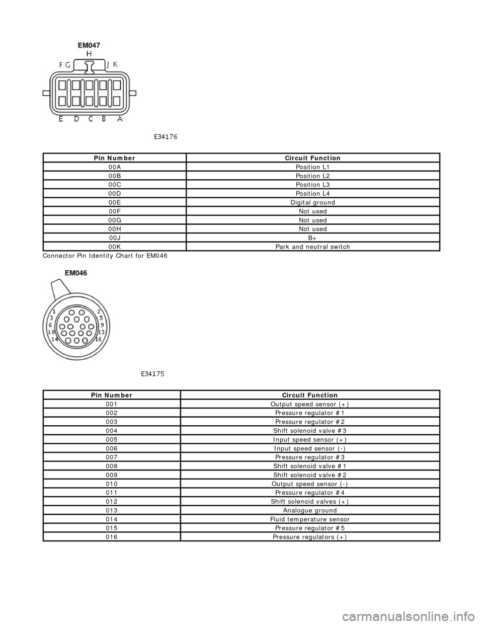
Connector Pin Identity Chart for EM046
Pin NumberCircuit Function
00APosition L1
00BPosition L2
00CPosition L3
00DPosition L4
00EDigital ground
00FNot used
00GNot used
00HNot used
00JB+
00KPark and neutral switch
Pin NumberCircuit Function
001Output speed sensor (+)
002Pressure regulator #1
003Pressure regulator #2
004Shift solenoid valve #3
005Input speed sensor (+)
006Input speed sensor (-)
007Pressure regulator #3
008Shift solenoid valve #1
009Shift solenoid valve #2
010Output speed sensor (-)
011Pressure regulator #4
012Shift solenoid valves (+)
013Analogue ground
014Fluid temperature sensor
015Pressure regulator #5
016Pressure regulators (+)
Page 1275 of 2490
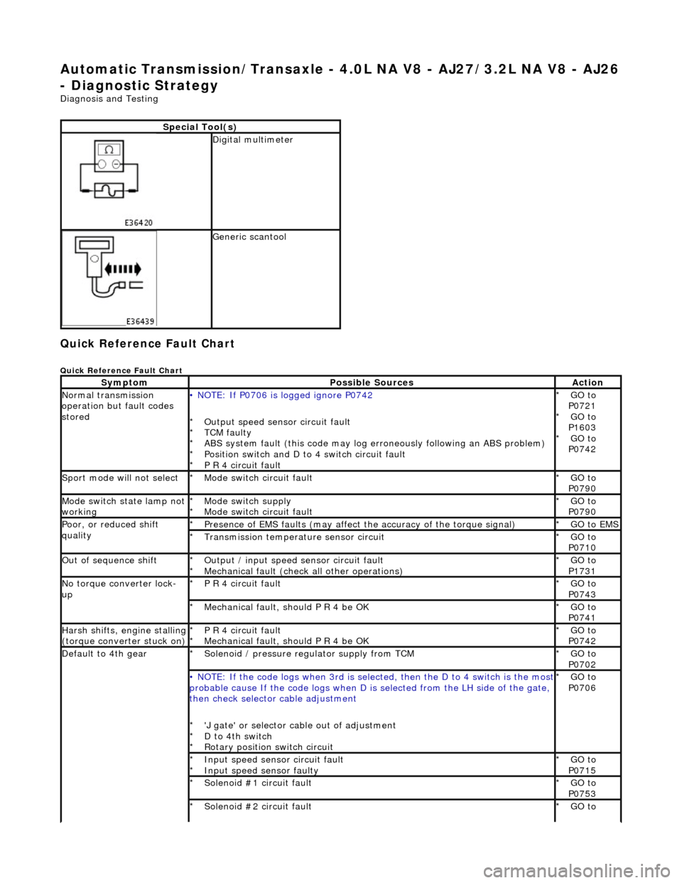
Automatic Transmission/Transaxle - 4.0L NA V8 - AJ27/3.2L NA V8 - AJ26
- Diagnostic Strategy
Diagnosis and Testing
Quick Reference Fault Chart
Quick Reference Fault Chart
Special Tool(s)
Digital multimeter
Generic scantool
SymptomPossible SourcesAction
Normal transmission
operation but fault codes
stored• NOTE: If P0706 is logged ignore P0742
Output speed sensor circuit fault
TCM faulty
ABS system fault (this code may log er roneously following an ABS problem)
Position switch and D to 4 switch circuit fault
P R 4 circuit fault
*
*
*
*
*
GO to
P0721 GO to
P1603 GO to
P0742
*
*
*
Sport mode will not selectMode switch circuit fault
*GO to
P0790
*
Mode switch state lamp not
workingMode switch supply
Mode switch circuit fault
*
*GO to
P0790
*
Poor, or reduced shift
qualityPresence of EMS faults
(may affect the accuracy of the torque signal)
*GO to EMS *
Transmission temperature sensor circuit
*GO to
P0710
*
Out of sequence shiftOutput / input speed sensor circuit fault
Mechanical fault (check all other operations)
*
*GO to
P1731
*
No torque converter lock-
upP R 4 circuit fault
*GO to
P0743
*
Mechanical fault, should P R 4 be OK
*GO to
P0741
*
Harsh shifts, engine stalling (torque converter stuck on)P R 4 circuit fault
Mechanical fault, should P R 4 be OK
*
*GO to
P0742
*
Default to 4th gearSolenoid / pressure regulator supply from TCM
*GO to
P0702
*
• NOTE: If the code logs wh
en 3rd is selected, then the D to 4 switch is the most probable cause If the code logs when D is selected fro m the LH side of the gate,
then check selector cable adjustment
'J gate' or selector ca ble out of adjustment
D to 4th switch
Rotary position switch circuit
*
*
*GO to
P0706
*
Input speed sensor circuit fault
Input speed sensor faulty
*
*GO to
P0715
*
Solenoid #1 circuit fault
*GO to
P0753
*
Solenoid #2 circuit fault
*GO to
*
Page 1276 of 2490
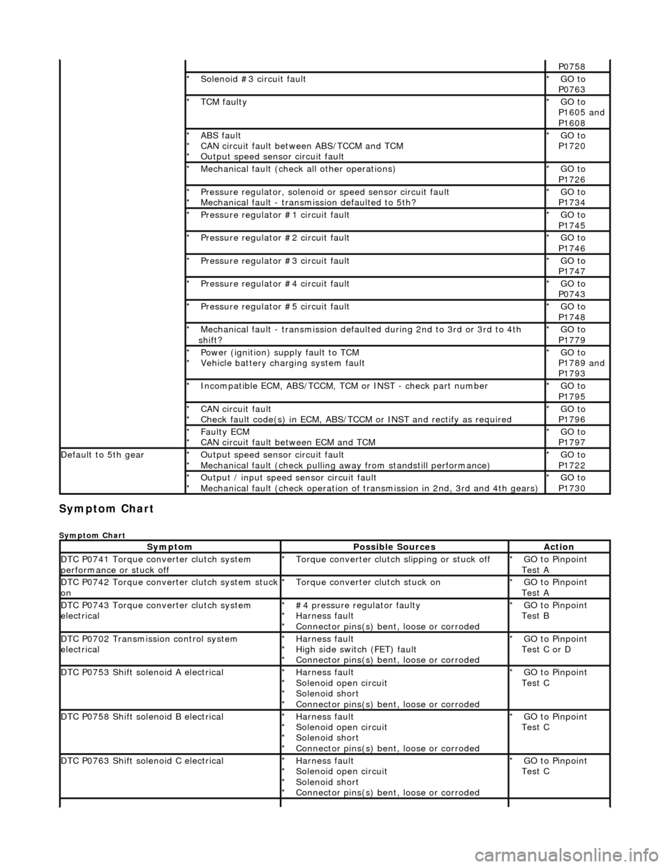
Symptom Chart
Symptom Chart
P0758
Solenoid #3 circuit fault
*GO to
P0763
*
TCM faulty
*GO to
P1605 and
P1608
*
ABS fault
CAN circuit fault between ABS/TCCM and TCM
Output speed sensor circuit fault
*
*
*GO to
P1720
*
Mechanical fault (check all other operations)
*GO to
P1726
*
Pressure regulator, solenoid
or speed sensor circuit fault
Mechanical fault - transmission defaulted to 5th?
*
*GO to
P1734
*
Pressure regulator #1 circuit fault
*GO to
P1745
*
Pressure regulator #2 circuit fault
*GO to
P1746
*
Pressure regulator #3 circuit fault
*GO to
P1747
*
Pressure regulator #4 circuit fault
*GO to
P0743
*
Pressure regulator #5 circuit fault
*GO to
P1748
*
Mechanical fault - transmission defaul
ted during 2nd to 3rd or 3rd to 4th
shift?
*GO to
P1779
*
Power (ignition) supply fault to TCM
Vehicle battery charging system fault
*
*GO to
P1789 and
P1793
*
Incompatible ECM, ABS/TCCM, TCM or INST - check part number
*GO to
P1795
*
CAN circuit fault
Check fault code(s) in ECM, ABS/TCCM or INST and rectify as required
*
*GO to
P1796
*
Faulty ECM
CAN circuit fault between ECM and TCM
*
*GO to
P1797
*
Default to 5th gearOutput speed sensor circuit fault
Mechanical fault (check pulling
away from standstill performance)
*
*GO to
P1722
*
Output / input speed sensor circuit fault
Mechanical fault (check operation of tr
ansmission in 2nd, 3rd and 4th gears)
*
*GO to
P1730
*
SymptomPossible SourcesAction
DTC P0741 Torque converter clutch system
performance or stuck offTorque converter clutch slipping or stuck off
*GO to Pinpoint
Test A
*
DTC P0742 Torque converter clutch system stuck onTorque converter clutch stuck on
*GO to Pinpoint
Test A
*
DTC P0743 Torque converter clutch system
electrical#4 pressure regulator faulty
Harness fault
Connector pins(s) bent
, loose or corroded
*
*
*GO to Pinpoint
Test B
*
DTC P0702 Transmission control system
electricalHarness fault
High side switch (FET) fault
Connector pins(s) bent
, loose or corroded
*
*
*GO to Pinpoint
Test C or D
*
DTC P0753 Shift solenoid A electricalHarness fault
Solenoid open circuit
Solenoid short
Connector pins(s) bent
, loose or corroded
*
*
*
*GO to Pinpoint
Test C
*
DTC P0758 Shift solenoid B electricalHarness fault
Solenoid open circuit
Solenoid short
Connector pins(s) bent
, loose or corroded
*
*
*
*GO to Pinpoint
Test C
*
DTC P0763 Shift solenoid C electricalHarness fault
Solenoid open circuit
Solenoid short
Connector pins(s) bent
, loose or corroded
*
*
*
*GO to Pinpoint
Test C
*
Page 1277 of 2490
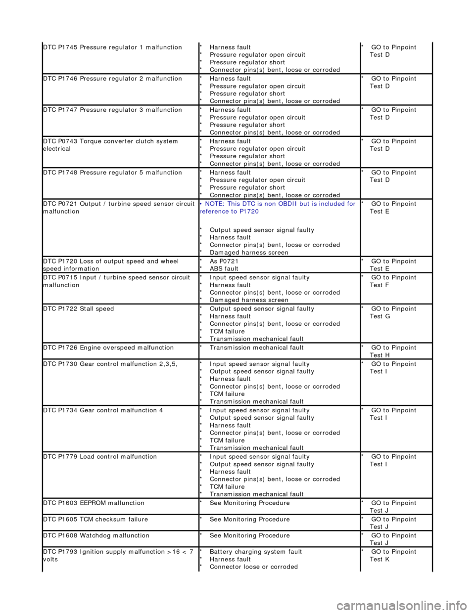
DTC P1745 Pressure regulator 1 malfunctionHarness fault
Pressure regulator open circuit
Pressure regulator short
Connector pins(s) bent, loose or corroded
*
*
*
*GO to Pinpoint
Test D
*
DTC P1746 Pressure regulator 2 malfunctionHarness fault
Pressure regulator open circuit
Pressure regulator short
Connector pins(s) bent
, loose or corroded
*
*
*
*GO to Pinpoint
Test D
*
DTC P1747 Pressure regulator 3 malfunctionHarness fault
Pressure regulator open circuit
Pressure regulator short
Connector pins(s) bent
, loose or corroded
*
*
*
*GO to Pinpoint
Test D
*
DTC P0743 Torque converter clutch system
electricalHarness fault
Pressure regulator open circuit
Pressure regulator short
Connector pins(s) bent
, loose or corroded
*
*
*
*GO to Pinpoint
Test D
*
DTC P1748 Pressure regulator 5 malfunctionHarness fault
Pressure regulator open circuit
Pressure regulator short
Connector pins(s) bent
, loose or corroded
*
*
*
*GO to Pinpoint
Test D
*
DTC P0721 Output / turbine speed sensor circuit
malfunction• NOTE: This DTC is non OBDII but is included for
reference to P1720
Output speed sensor signal faulty
Harness fault
Connector pins(s) bent , loose or corroded
Damaged harness screen
*
*
*
*GO to Pinpoint
Test E
*
DTC P1720 Loss of output speed and wheel
speed informationAs P0721
ABS fault
*
*GO to Pinpoint
Test E
*
DTC P0715 Input / turbine speed sensor circuit
malfunctionInput speed sensor signal faulty
Harness fault
Connector pins(s) bent
, loose or corroded
Damaged harness screen
*
*
*
*GO to Pinpoint
Test F
*
DTC P1722 Stall speedOutput speed sensor signal faulty
Harness fault
Connector pins(s) bent
, loose or corroded
TCM failure
Transmission mechanical fault
*
*
*
*
*GO to Pinpoint
Test G
*
DTC P1726 Engine overspeed malfunctionTransmission mechanical fault
*GO to Pinpoint
Test H
*
DTC P1730 Gear control malfunction 2,3,5,Input speed sensor signal faulty
Output speed sensor signal faulty
Harness fault
Connector pins(s) bent
, loose or corroded
TCM failure
Transmission mechanical fault
*
*
*
*
*
*GO to Pinpoint
Test I
*
DTC P1734 Gear control malfunction 4Input speed sensor signal faulty
Output speed sensor signal faulty
Harness fault
Connector pins(s) bent
, loose or corroded
TCM failure
Transmission mechanical fault
*
*
*
*
*
*GO to Pinpoint
Test I
*
DTC P1779 Load control malfunctionInput speed sensor signal faulty
Output speed sensor signal faulty
Harness fault
Connector pins(s) bent
, loose or corroded
TCM failure
Transmission mechanical fault
*
*
*
*
*
*GO to Pinpoint
Test I
*
DTC P1603 EEPROM malfunctionSee Monitoring Procedure
*GO to Pinpoint
Test J
*
DTC P1605 TCM checksum failureSee Monitoring Procedure
*GO to Pinpoint
Test J
*
DTC P1608 Watchdog malfunctionSee Monitoring Procedure
*GO to Pinpoint
Test J
*
DTC P1793 Ignition supply malfunction >16 < 7
voltsBattery charging system fault
Harness fault
Connector loose or corroded
*
*
*GO to Pinpoint
Test K
*
Page 1306 of 2490
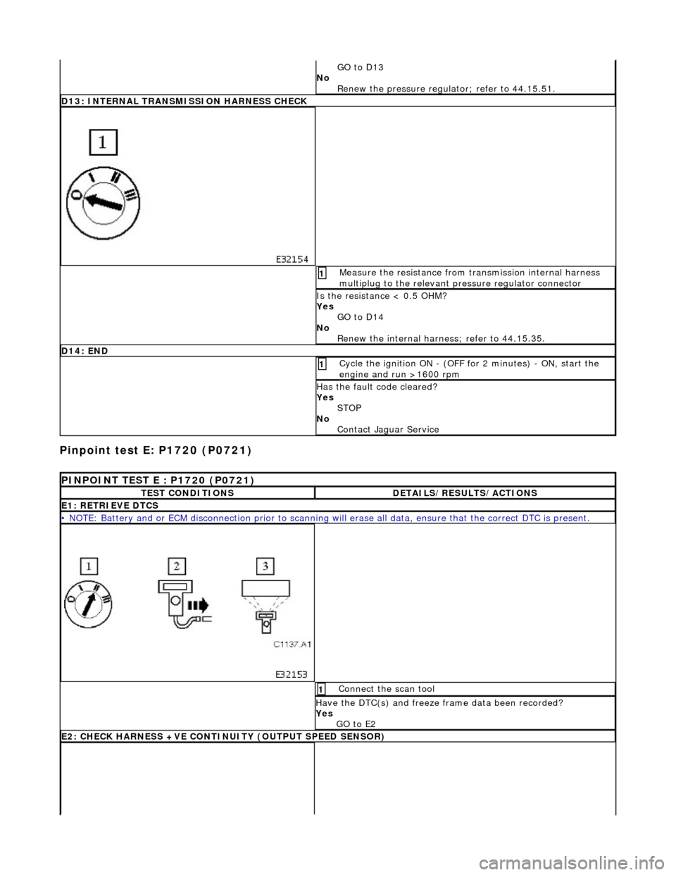
Pinpoint test E: P1720 (P0721)
GO to D13
No Renew the pressure regulator; refer to 44.15.51.
D13: INTERNAL TRANSMISSION HARNESS CHECK
Measure the resistance from transmission internal harness
multiplug to the relevant pr essure regulator connector 1
Is the resistance < 0.5 OHM?
Yes
GO to D14
No Renew the internal harnes s; refer to 44.15.35.
D14: END
Cycle the ignition ON - (OFF for 2 minutes) - ON, start the
engine and run >1600 rpm 1
Has the fault code cleared?
Yes
STOP
No Contact Jaguar Service
PINPOINT TEST E : P1720 (P0721)
TEST CONDITIONSDETAILS/RESULTS/ACTIONS
E1: RETRIEVE DTCS
• NOTE: Battery and or ECM disconnection prior to scanning wi ll erase all data, ensure that the correct DTC is present.
Connect the scan tool 1
Have the DTC(s) and freeze frame data been recorded?
Yes GO to E2
E2: CHECK HARNESS +VE CONTIN UITY (OUTPUT SPEED SENSOR)