Page 2211 of 3573
7A±57 AUTOMATIC TRANSMISSION (4L30±E)
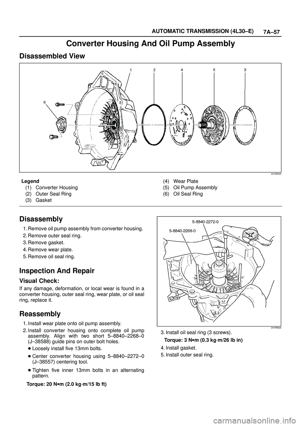
Converter Housing And Oil Pump Assembly
Disassembled View
241RW003
Legend
(1) Converter Housing
(2) Outer Seal Ring
(3) Gasket(4) Wear Plate
(5) Oil Pump Assembly
(6) Oil Seal Ring
Disassembly
1. Remove oil pump assembly from converter housing.
2. Remove outer seal ring.
3. Remove gasket.
4. Remove wear plate.
5. Remove oil seal ring.
Inspection And Repair
Visual Check:
If any damage, deformation, or local wear is found in a
converter housing, outer seal ring, wear plate, or oil seal
ring, replace it.
Reassembly
1. Install wear plate onto oil pump assembly.
2. Install converter housing onto complete oil pump
assembly. Align with two short 5±8840±2268±0
(J±38588) guide pins on outer bolt holes.
�Loosely install five 13mm bolts.
�Center converter housing using 5±8840±2272±0
(J±38557) centering tool.
�Tighten five inner 13mm bolts in an alternating
pattern.
Torque: 20 Nwm (2.0 kg´m/15 lb ft)241RW020
3. Install oil seal ring (3 screws).
Torque: 3 Nwm (0.3 kg´m/26 lb in)
4. Install gasket.
5. Install outer seal ring.
Page 2212 of 3573
7A±58
AUTOMATIC TRANSMISSION (4L30±E)
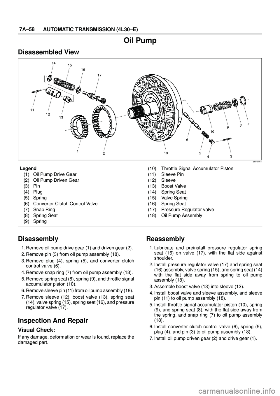
Oil Pump
Disassembled View
241RS014
Legend
(1) Oil Pump Drive Gear
(2) Oil Pump Driven Gear
(3) Pin
(4) Plug
(5) Spring
(6) Converter Clutch Control Valve
(7) Snap Ring
(8) Spring Seat
(9) Spring(10) Throttle Signal Accumulator Piston
(11) Sleeve Pin
(12) Sleeve
(13) Boost Valve
(14) Spring Seat
(15) Valve Spring
(16) Spring Seat
(17) Pressure Regulator valve
(18) Oil Pump Assembly
Disassembly
1. Remove oil pump drive gear (1) and driven gear (2).
2. Remove pin (3) from oil pump assembly (18).
3. Remove plug (4), spring (5), and converter clutch
control valve (6).
4. Remove snap ring (7) from oil pump assembly (18).
5. Remove spring seat (8), spring (9), and throttle signal
accumulator piston (10).
6. Remove sleeve pin (11) from oil pump assembly (18).
7. Remove sleeve (12), boost valve (13), spring seat
(14), valve spring (15), spring seat (16), and pressure
regulator valve (17).
Inspection And Repair
Visual Check:
If any damage, deformation or wear is found, replace the
damaged part.
Reassembly
1. Lubricate and preinstall pressure regulator spring
seat (16) on valve (17), with the flat side against
shoulder.
2. Install pressure regulator valve (17) and spring seat
(16) assembly, valve spring (15), and spring seat (14)
with the flat side away from spring to oil pump
assembly (18).
3. Assemble boost valve (13) into sleeve (12).
4. Install boost valve and sleeve assembly, and sleeve
pin (11) to oil pump assembly (18).
5. Install throttle signal accumulator piston (10), spring
(9), and spring seat (8), with the flat side away from
the spring, and snap ring (7) to oil pump assembly
(18).
6. Install converter clutch control valve (6), spring (5),
plug (4), and pin (3) to oil pump assembly (18).
7. Install oil pump driven gear (2) and drive gear (1).
Page 2214 of 3573
7A±60
AUTOMATIC TRANSMISSION (4L30±E)
10. Remove retainer (13), 2±3 shift valve (14), and spring
(15).
11. Remove spring pin (16), plug (17), spring (18), and
low pressure control valve (19).
12. Remove spring pin (20), plug (21), and band control
screen assembly (22).
13. Remove spring pin (23), plug (24), 1±2 accumulator
valve (25), and 1±2 accumulator control valve (26).
14. Remove check ball (27) from valve body (28).
Inspection And Repair
Inspect for the following, and replace any damaged or
worn parts:
1. Damage or wear to each valve.
2. Damage in oil passeges.
3. Cracks or damage to valve body.
4. Valve operations.
5. Spring fatigue.
Reassembly
1. Install 1±2 accumulator control valve (26), 1±2
accumulator valve (25), plug (24), and spring pin (23).
2. Install band control screen assembly (22), plug (21),
and spring pin (20).
3. Install low pressure control valve (19), spring (18),
plug (17), and spring pin (16).
4. Install spring (15), 2±3 shift valve (14), retainer (13),
solenoid B (12), and spring pin (11).
5. Install spring (10), 1±2/3±4 shift valve (9), retainer (8),
solenoid A (7), and spring pin (6).
6. Install waved washer (5), band control solenoid (3),
and pin (4).
7. Install manual valve (2).
8. Install check ball (27) to valve body (28).
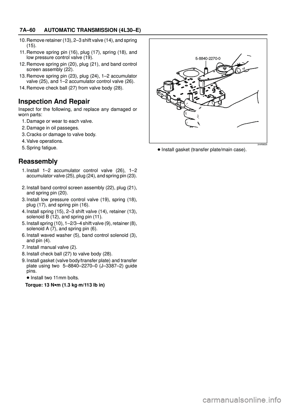
9. Install gasket (valve body/transfer plate) and transfer
plate using two 5±8840±2270±0 (J±3387±2) guide
pins.
�Install two 11mm bolts.
Torque: 13 Nwm (1.3 kg´m/113 lb in)
244RW004
�Install gasket (transfer plate/main case).
Page 2215 of 3573
7A±61 AUTOMATIC TRANSMISSION (4L30±E)
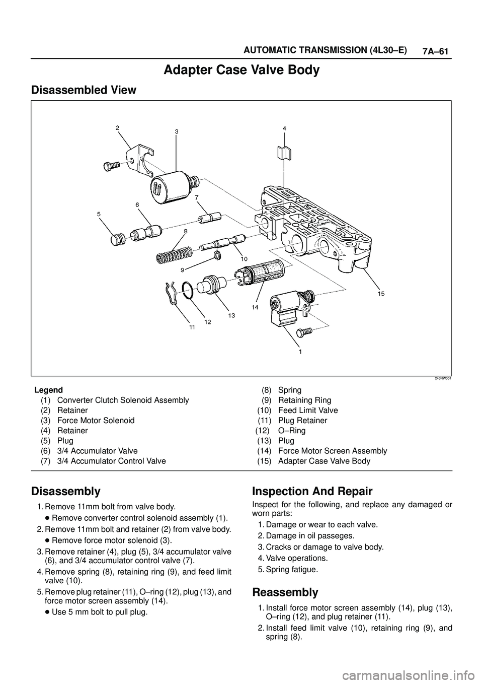
Adapter Case Valve Body
Disassembled View
243RW001
Legend
(1) Converter Clutch Solenoid Assembly
(2) Retainer
(3) Force Motor Solenoid
(4) Retainer
(5) Plug
(6) 3/4 Accumulator Valve
(7) 3/4 Accumulator Control Valve(8) Spring
(9) Retaining Ring
(10) Feed Limit Valve
(11) Plug Retainer
(12) O±Ring
(13) Plug
(14) Force Motor Screen Assembly
(15) Adapter Case Valve Body
Disassembly
1. Remove 11mm bolt from valve body.
�Remove converter control solenoid assembly (1).
2. Remove 11mm bolt and retainer (2) from valve body.
�Remove force motor solenoid (3).
3. Remove retainer (4), plug (5), 3/4 accumulator valve
(6), and 3/4 accumulator control valve (7).
4. Remove spring (8), retaining ring (9), and feed limit
valve (10).
5. Remove plug retainer (11), O±ring (12), plug (13), and
force motor screen assembly (14).
�Use 5 mm bolt to pull plug.
Inspection And Repair
Inspect for the following, and replace any damaged or
worn parts:
1. Damage or wear to each valve.
2. Damage in oil passeges.
3. Cracks or damage to valve body.
4. Valve operations.
5. Spring fatigue.
Reassembly
1. Install force motor screen assembly (14), plug (13),
O±ring (12), and plug retainer (11).
2. Install feed limit valve (10), retaining ring (9), and
spring (8).
Page 2231 of 3573
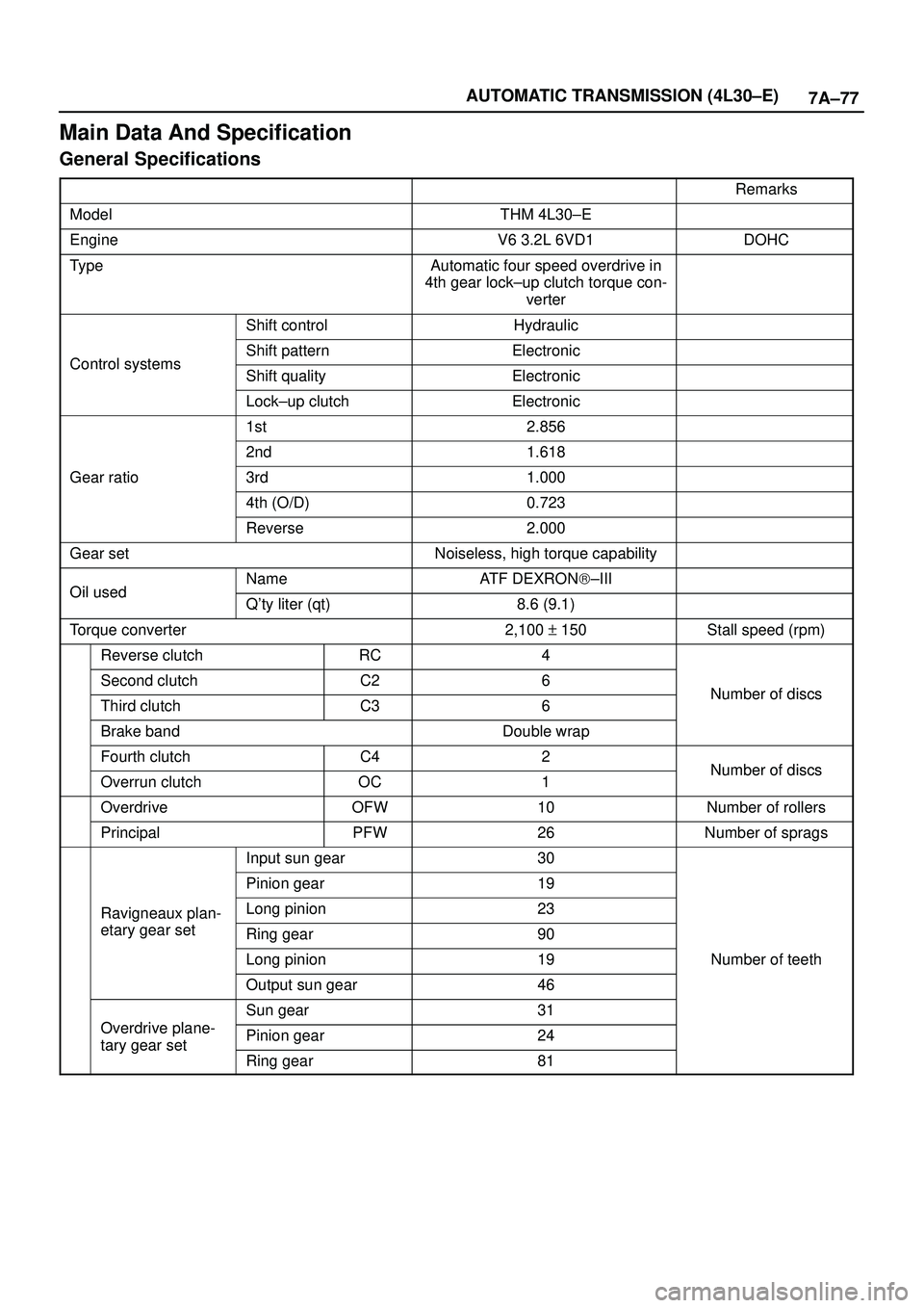
7A±77 AUTOMATIC TRANSMISSION (4L30±E)
Main Data And Specification
General Specifications
Remarks
ModelTHM 4L30±E
EngineV6 3.2L 6VD1DOHC
TypeAutomatic four speed overdrive in
4th gear lock±up clutch torque con-
verter
Shift controlHydraulic
Control systemsShift patternElectronicControl systemsShift qualityElectronic
Lock±up clutchElectronic
1st2.856
2nd1.618
Gear ratio3rd1.000
4th (O/D)0.723
Reverse2.000
Gear setNoiseless, high torque capability
Oil usedNameATF DEXRON)±IIIOil usedQ'ty liter (qt)8.6 (9.1)
Torque converter2,100 + 150Stall speed (rpm)
Reverse clutchRC4
Second clutchC26Number of discsThird clutchC36Number of discs
Brake bandDouble wrap
Fourth clutchC42Number of discsOverrun clutchOC1Number of discs
OverdriveOFW10Number of rollers
PrincipalPFW26Number of sprags
Input sun gear30
Pinion gear19
Ravigneaux plan-Long pinion23g
etary gear setRing gear90
Long pinion19Number of teeth
Output sun gear46
Odi l
Sun gear31
Overdrive plane-
tary gear setPinion gear24tary gear set
Ring gear81
Page 2236 of 3573
7A±82
AUTOMATIC TRANSMISSION (4L30±E)
ILLUSTRATIONTOOL NO.
TOOL NAME
5±8840±2268±0
(J±38588)
Guide pins; adapter
case to main case
5±8840±2269±0
(J±38555)
Overrun clutch piston
seal installer set
5±8840±2270±0
(J±3387±2)
Guide pins; gasket and
transfer plate to valve
body
5±8840±2271±0
(J±25022)
Turbine shaft puller (Use
with 5±8840±0618±0
(J±24773±1))
5±8840±0196±0
(J±23129)
Oil seal remover (Use
with 5±8840±2266±0
(J±23907) and
5±8840±0019±0
(J±38584))
5±8840±2272±0
(J±38557)
Oil pump centering tool
ILLUSTRATIONTOOL NO.
TOOL NAME
5±8840±2273±0
(J±23082±01)
Oil pump rotation tool
5±8840±0022±0
(J±25025±B)
Guide pins; valve body
to main case
5±8840±2274±0
(J±38428)
Servo piston fitter
5±8840±2275±0
(J±23327±91)
Overrun clutch spring
compressor
5±8840±2277±1
(J±38559±A)
3/4 Accumulator piston
cover compressor
5±8840±2278±0
(J±8763±02)
Holding fixture
Page 2237 of 3573
7A±83 AUTOMATIC TRANSMISSION (4L30±E)
ILLUSTRATIONTOOL NO.
TOOL NAME
5±8840±2282±0
(J±36797)
A/T extension housing
oil seal installer (Inside)
5±8840±0003±0
(J±3289±20)
Holding fixture base
5±8840±0004±0
Pressure gauge
5±8840±0618±0
(J±24773±1)
End play fixture (Use
with 5±8840±2271±0
(J±25022))
5±8840±0019±0 &
5±8840±2000±0
(J±23907)
Slide hammer
Page 2238 of 3573
7A±84
AUTOMATIC TRANSMISSION (4L30±E)
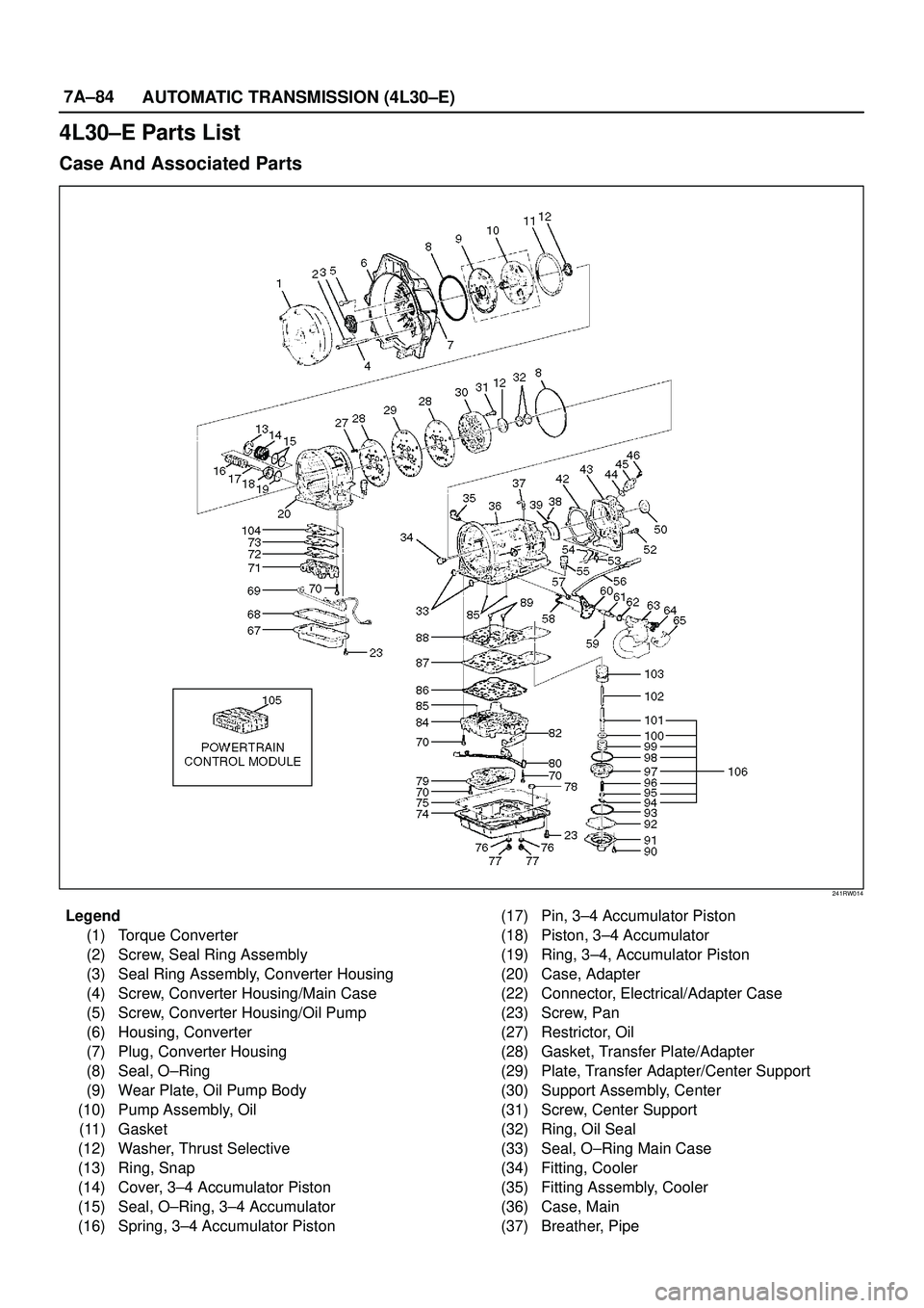
4L30±E Parts List
Case And Associated Parts
241RW014
Legend
(1) Torque Converter
(2) Screw, Seal Ring Assembly
(3) Seal Ring Assembly, Converter Housing
(4) Screw, Converter Housing/Main Case
(5) Screw, Converter Housing/Oil Pump
(6) Housing, Converter
(7) Plug, Converter Housing
(8) Seal, O±Ring
(9) Wear Plate, Oil Pump Body
(10) Pump Assembly, Oil
(11) Gasket
(12) Washer, Thrust Selective
(13) Ring, Snap
(14) Cover, 3±4 Accumulator Piston
(15) Seal, O±Ring, 3±4 Accumulator
(16) Spring, 3±4 Accumulator Piston(17) Pin, 3±4 Accumulator Piston
(18) Piston, 3±4 Accumulator
(19) Ring, 3±4, Accumulator Piston
(20) Case, Adapter
(22) Connector, Electrical/Adapter Case
(23) Screw, Pan
(27) Restrictor, Oil
(28) Gasket, Transfer Plate/Adapter
(29) Plate, Transfer Adapter/Center Support
(30) Support Assembly, Center
(31) Screw, Center Support
(32) Ring, Oil Seal
(33) Seal, O±Ring Main Case
(34) Fitting, Cooler
(35) Fitting Assembly, Cooler
(36) Case, Main
(37) Breather, Pipe