Page 951 of 3573

5D Ð 6 PARKING BRAKES
GENERAL DESCRIPTION
Pulling up the parking brake lever by hand will set the parking brake. Once pulled up, the lever is held by
means of a ratchet type lock until it is released. The position of the lever is transmitted through
cable/lever systems to the rear wheels. These parts are designed to obtain sufficient braking force when
parking on slopes. When the parking brake is set, or when the ignition SW is in the ÒONÓ position, the
brake warning light illuminates. The rear wheel parking brake is a duo-servo brake (mechanical inside
expansion type) built-in to rear disc brake. Parking brake adjustment is made through the adjusting hole
(bored through back plate). Parking brake lever stroke should be adjusted to 6 or 7 notches.
OPERATION
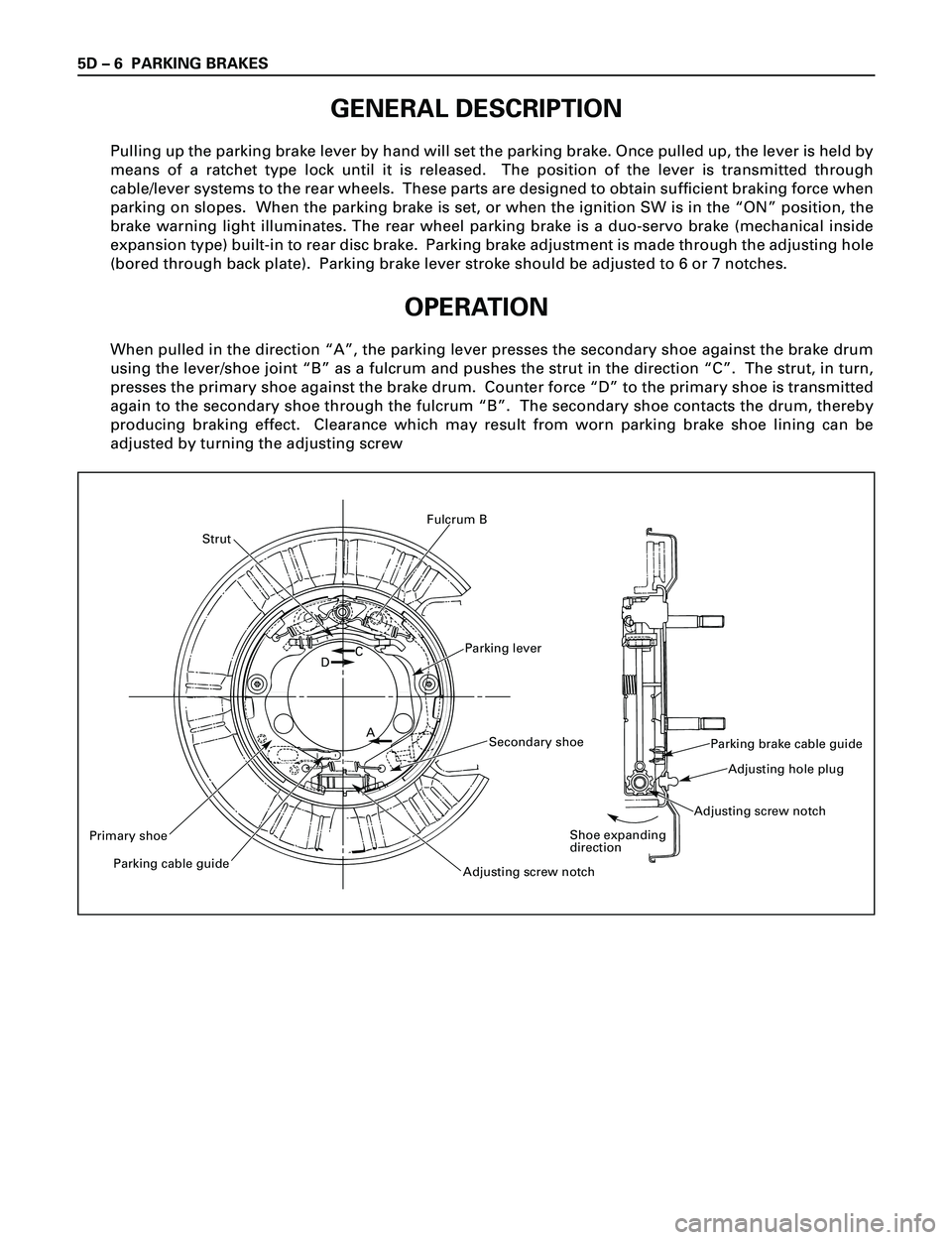
When pulled in the direction ÒAÓ, the parking lever presses the secondary shoe against the brake drum
using the lever/shoe joint ÒBÓ as a fulcrum and pushes the strut in the direction ÒCÓ. The strut, in turn,
presses the primary shoe against the brake drum. Counter force ÒDÓ to the primary shoe is transmitted
again to the secondary shoe through the fulcrum ÒBÓ. The secondary shoe contacts the drum, thereby
producing braking effect. Clearance which may result from worn parking brake shoe lining can be
adjusted by turning the adjusting screw
Parking lever
Strut
Primary shoe
Parking cable guide
Adjusting screw notch
Secondary shoe
DC
A
Fulcrum B
Parking brake cable guide
Adjusting hole plug
Adjusting screw notch
Shoe expanding
direction
Page 952 of 3573
PARKING BRAKES 5D Ð 7
Adjusting nut
Equalizer
ON-VEHICLE SERVICE
PARKING BRAKE LEVER REPLACEMENT
3 5
1
2
4
6
Removal Steps
1. Ajusting nut
2. Equalizer
3. Bolt
4. Switch connector
5. Parking brake lever
6. Parking brake front cable
Installation Steps
To install, follow the removal steps in the
reverse order.
REMOVAL
1. Ajusting Nut
2. Equalizer
3. Bolt
Remove the center console as described in Body
and Accessories section.
Then remove the fixing bolt.
4. Switch Connector
5. Parking Brake Lever
6. Parking Brake Front Cable
331RW007
331RW008
Page 953 of 3573
5D Ð 8 PARKING BRAKES
INSTALLATION
6. Parking Brake Front Cable
5. Parking Brake Lever
·Apply grease (BESCO L-2 or equivalent) to front
cable contact point.
4. Switch Connector
3. Bolt
·Tighten the parking brake lever fixing bolt to the
specified torque.
Bolt Torque Nám (kgám / lbáft)
15 (1.5 / 11)
·Install the center console.
2. Equalizer
1. Adjusting Nut
Page 954 of 3573
PARKING BRAKES 5D Ð 9
PARKING BRAKE CABLE
5
7
4
2
3
1
6 7
1215
1314
AB
108
9
10
11 169 8
AB
Removal Steps
1. Rear wheels
2. Caliper assembly
3. Rotor (Drum)
4. Holding spring
5. Return spring; upper
6. Return spring; lower
7. Shoe assembly
8. Cable fixing bolt
9. Clip
10. Clip
11. Clip
12. Adjust nut
13. Equalizer
14. Bolt
15. Retaining plate
16. Parking brake cable
Installation Steps
To install, follow the removal steps in the
reverse order.
331RW009
Page 955 of 3573

5D Ð 10 PARKING BRAKES
INSTALLATION
To install, follow the removal steps in the reverse
order, noting the following points.
15. Parking Brake Cable
·Apply grease (BESCO L-2 or equivalent) to the
connecting portion of the rear cable and equalizer.
12. Adjust Nut
·Tighten the adjust nut to the specified torque.
Adjust Nut Torque Nám (kgácm / lbáin)
6 (60 / 52)
·To adjust the parking brake, refer to Parking Brake
Adjustment in this section.
11. Clip
·Tighten the fixing bolt to the specified torque.
Fixing Bolt Torque Nám (kgácm / lbáin)
15 (150 / 130)
10. Clip
·Tighten the fixing bolt to the specified torque.
Fixing Bolt Torque Nám (kgácm / lbáin)
6.5 (65 / 58)
REMOVAL
1. Rear Wheels
2. Caliper Assembly
·Remove 2 bolts to remove the caliper assembly
from the support bracket. (Refer to Rear Disc
Brakes in Power Assisted Brake System section.)
Temporarily hang the caliper with wire to avoid
stretching the brake hose.
3. Rotor (Drum)
4. Holding Spring
5. Return Spring; Upper
6. Return Spring; Lower
7. Shoe Assembly
·Remove the brake shoe assembly. Then remove
the parking brake cable from the parking brake
lever.
8. Cable Fixing Bolt
9. Clip
10. Clip
11. Clip
12. Adjust Nut
13. Equalizer
14. Bolt
15. Retaining Plate
16. Parking Brake Cable
Parking brake lever
Page 956 of 3573
PARKING BRAKES 5D Ð 11
9. Clip
·Tighten the fixing bolt to the specified torque.
Fixing Bolt Torque Nám (kgácm / lbáin)
7.8 (78 / 67)
8. Cable Fixing Bolt
·Tighten the cable fixing bolt to the specified
torque.
Cable Fixing Bolt Torque Nám (kgácm / lbáin)
6.5 (65 / 58)
7. Shoe Assembly
·After installation of the shoe and cable assembly,
apply special grease (included in the repair kit) to
the following portions indicated in the left figure.
5. Return Spring; Upper
·The parking brake lever side (secondary side)
return spring must be installed on the outer side
of the primary side return spring.
Outer side
Parking lever
Page 2287 of 3573

7A1±42
TRANSMISSION CONTROL SYSTEM (4L30±E)
DTC P0719 TCC Brake Switch Circuit High (Stuck On)
D07RW032
Circuit Description
The TCC brake switch is used to indicate brake pedal
status. The normally opened brake switch signal voltage
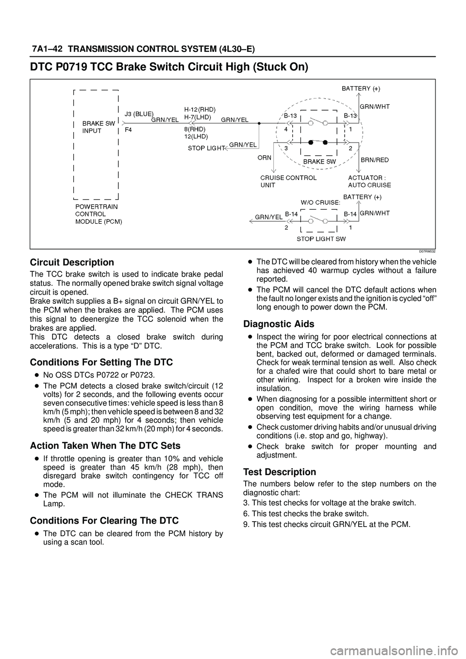
circuit is opened.
Brake switch supplies a B+ signal on circuit GRN/YEL to
the PCM when the brakes are applied. The PCM uses
this signal to deenergize the TCC solenoid when the
brakes are applied.
This DTC detects a closed brake switch during
accelerations. This is a type ªDº DTC.
Conditions For Setting The DTC
�No OSS DTCs P0722 or P0723.
�The PCM detects a closed brake switch/circuit (12
volts) for 2 seconds, and the following events occur
seven consecutive times: vehicle speed is less than 8
km/h (5 mph); then vehicle speed is between 8 and 32
km/h (5 and 20 mph) for 4 seconds; then vehicle
speed is greater than 32 km/h (20 mph) for 4 seconds.
Action Taken When The DTC Sets
�If throttle opening is greater than 10% and vehicle
speed is greater than 45 km/h (28 mph), then
disregard brake switch contingency for TCC off
mode.
�The PCM will not illuminate the CHECK TRANS
Lamp.
Conditions For Clearing The DTC
�The DTC can be cleared from the PCM history by
using a scan tool. �The DTC will be cleared from history when the vehicle
has achieved 40 warmup cycles without a failure
reported.
�The PCM will cancel the DTC default actions when
the fault no longer exists and the ignition is cycled ªoffº
long enough to power down the PCM.
Diagnostic Aids
�Inspect the wiring for poor electrical connections at
the PCM and TCC brake switch. Look for possible
bent, backed out, deformed or damaged terminals.
Check for weak terminal tension as well. Also check
for a chafed wire that could short to bare metal or
other wiring. Inspect for a broken wire inside the
insulation.
�When diagnosing for a possible intermittent short or
open condition, move the wiring harness while
observing test equipment for a change.
�Check customer driving habits and/or unusual driving
conditions (i.e. stop and go, highway).
�Check brake switch for proper mounting and
adjustment.
Test Description
The numbers below refer to the step numbers on the
diagnostic chart:
3. This test checks for voltage at the brake switch.
6. This test checks the brake switch.
9. This test checks circuit GRN/YEL at the PCM.
Page 2877 of 3573
8DÐ284 WIRING SYSTEM
Anti-lock Brake System (ABS)
General Description
The circuit consists of EHCU (Electronic Hydraulic
Control Unit), wheel speed sensor, GÐsensor,
stoplight switch or brake switch (w/cruise control),
backup light switch, transmission switchÐ1, 2,
indicator light and data link connector.
EHCU controls brake fluid pressure applied to front
and rear wheels to prevent wheels from locking by
using speed sensor and GÐsensor signals.
Based on wheel speed signals from speed sensor,
EHCU activates solenoid valves incorporated into
the control unit to increase, maintain or decrease
brake fluid pressure.
Refer to AntiÐlock Brake System in Brakes section.