Page 902 of 3573

5C – 24 POWER ASSISTED BRAKE SYSTEM
DISC BRAKES
The disc brake assembly consists of a caliper, piston, rotor, pad assembly and support bracket. The
caliper assembly has a single bore and is mounted to the support bracket with 2 mounting bolts. The
support bracket allows the caliper to move laterally against the rotor. The caliper is a one-piece casting
with the inboard side containing the piston bore. A square cut rubber seal is located in a groove in the
piston bore which provides the hydraulic seal between the piston and the cylinder wall.
NOTE:
1) Replace all components included in repair kits used to service this caliper.
2) Lubricate rubber parts with clean brake fluid to ease assembly.
3) If any hydraulic component is removed or disconnected, it may be necessary to bleed all or part of
the brake system.
4) Replace pads in axle sets only.
5) The torque values specified are for dry, unlubricated fasteners.
6) Perform service operation a clean bench free from all mineral oil materials.
OPERATION
Hydraulic pressure, created by applying the brake pedal, is converted by the caliper to a stopping force.
This force acts equally against the piston and the bottom of the caliper bore to move the piston outward
and to move (slide) the caliper inward resulting in a clamping action on the rotor. This clamping action
forces the linings against the rotor, creating friction to stop the vehicle.
Front disc brakes
Rear disc brakes
Page 904 of 3573
 Raise the vehicle and support it with suitable
safety stands.
2) Remove wheel and tire assembly.
3) Clean dirt, grease, and other foreign")
5C – 26 POWER ASSISTED BRAKE SYSTEM
REMOVAL
Preparation:
1) Raise the vehicle and support it with suitable
safety stands.
2) Remove wheel and tire assembly.
3) Clean dirt, grease, and other foreign material off
the hose fittings at both ends.
Front/Rear Caliper Brake Hose
1. Brake Pipe
2. Clip
3. Bolt and Gasket
4. Hose
Rear Axle Brake Hose
1. Brake Pipe
2. Clip
3. Brake Pipe
4. Bolt
5. Hose
INSTALLATION
To install, follow the removal steps in the reverse
order, noting the following points. After installing the
brake hoses, bleed brakes as described in this
section.
Front/Rear Caliper Brake Hose
1. Tighten the brake pipes to the specified torque.
Brake Pipe Torque N·m(kg·m/lb·ft)
16 (1.6 / 12)
2. Tighten the bolt to the specified torque.
Bolt Torque N·m(kg·m/lb·ft)
35 (3.5 / 26)
NOTE:
•Always use new copper gaskets.
•Be sure to put the hooked edge of the flexible
hose end into the anti-rotation cavity.
Rear Axle Brake Hose
1. Tighten the brake pipes to the specified torque.
Brake Pipe Torque N·m(kg·m/lb·ft)
16 (1.6 / 12)
2. Tighten the bolt to the specified torque.
Bolt Torque N·m(kg·cm/lb·in)
13 (130 / 113)
Page 906 of 3573
 VALVE
Master cylinder
(Primary) Master cylinder
(Secondary)
Rear brakeFront brake
INSTALLATION
To install, follow the rem")
5C – 28 POWER ASSISTED BRAKE SYSTEM
P & B (PROPORTIONING AND BYPASS) VALVE
Master cylinder
(Primary) Master cylinder
(Secondary)
Rear brakeFront brake
INSTALLATION
To install, follow the removal steps in the reverse
order, noting the following points. After installing the
brake pipes, bleed brakes as described in this section.
1. Tighten the brake pipes to the specified torque.
Brake Pipe Torque N·m(kg·m/lb·ft)
Master Cylinder Side Others
12 (1.2/9) 16 (1.6/12)
The P & B valve contains two sections, each serving a
different function.
The proportioning section of the P & B valve
proportions outlet pressure to the rear brakes after a
predetermined rear input pressure has been reached.
This is done to prevent rear wheel lock-up on the
vehicles with light rear wheel loads.
The valve has a By-bass feature which assures full
system pressure to the rear brakes in the event of a
font brake mulfunction, also full front pressure is
retained in the event of rear brake mulfunction.
The P & B valve is not repairable and must be
replaced as a complete assembly.
Page 907 of 3573
POWER ASSISTED BRAKE SYSTEM 5C – 29
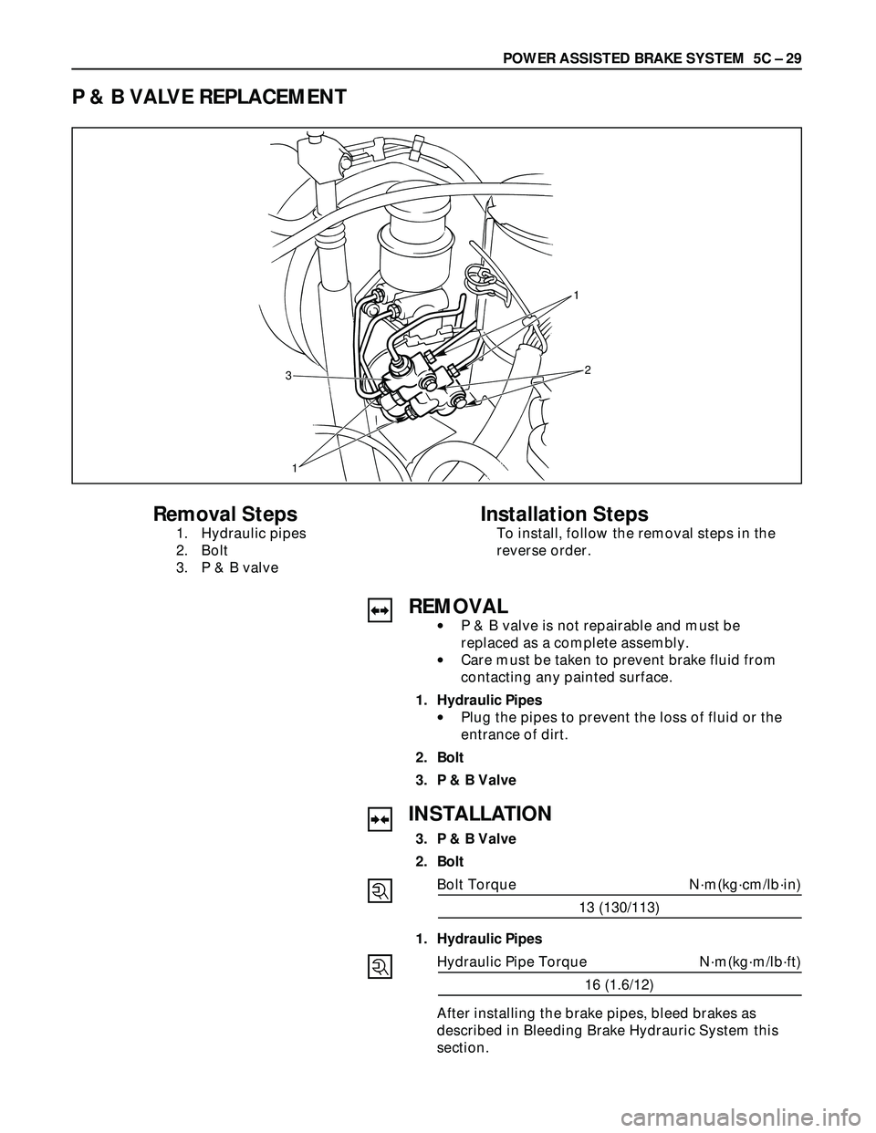
P & B VALVE REPLACEMENT
1
3
1�y�y
2
Removal Steps
1. Hydraulic pipes
2. Bolt
3. P & B valve
Installation Steps
To install, follow the removal steps in the
reverse order.
REMOVAL
•P & B valve is not repairable and must be
replaced as a complete assembly.
•Care must be taken to prevent brake fluid from
contacting any painted surface.
1. Hydraulic Pipes
•Plug the pipes to prevent the loss of fluid or the
entrance of dirt.
2. Bolt
3. P & B Valve
INSTALLATION
3. P & B Valve
2. Bolt
Bolt Torque N·m(kg·cm/lb·in)
13 (130/113)
1. Hydraulic Pipes
Hydraulic Pipe Torque N·m(kg·m/lb·ft)
16 (1.6/12)
After installing the brake pipes, bleed brakes as
described in Bleeding Brake Hydrauric System this
section.
Page 908 of 3573
5C – 30 POWER ASSISTED BRAKE SYSTEM
LOAD SENSING PROPORTIONING VALVE (LSPV)
(FOR EUROPE AND SOUTH AFRICA)
to rear wheel cylinder
from front master cylinder
from rear master cylinder
Structure and Operation
The following is an explanation of the structure and
operation of the linkage type load sensing device.
This device controls the fluid pressure to the rear
brakes in accordance with changes in rear axle load
(vertical displacements of the rear axle springs).
•Structure
This device consists of a load sensing lever and a
valve.
The valve is mounted through a bracket to the
frame. One end of the load sensing lever is fixed
to the valve at the frame and the other end to the
rear axle housing through a spring.
F05RW003
Page 910 of 3573
 When the front brake system fails.
When there is a failure in the front brake system,
the fluid pressure from the front master cylinder
decreases. As a result")
5C – 32 POWER ASSISTED BRAKE SYSTEM
(4) When the front brake system fails.
When there is a failure in the front brake system,
the fluid pressure from the front master cylinder
decreases. As a result, the balance between the
front and rear brake side fluid pressures is lost at
the control valve sleeve so that the control valve
sleeve moves upwards.
The control valve sleeve strikes against the piston,
thereby pushing the piston upwards.
Accordingly, the fluid pressure of the rear master
cylinder is not decreased and is applied directly to
the rear wheel cylinder to secure a sufficient
braking performance of the rear brakes. (See the
left figure.)
Valve Maintenance
In the case of fluid leak or other abnormalities, faulty
valve should be replaced.
Note:
The load sensing proportioning valve is not
repairable and must be replaced as a complete
assembly.
ADJUSTMENT PROCEDURE OF LSPV
1. Adjust the rear axle weight by loading the
laggage compartmemt as necessary.
Rear Axle Weight N (kg / lb)
10,300 (1,050 / 2,315)
Note:
The rear axle weight should be adjusted to the
specified value with a man seated in the driver seat.
Rear master cylinder
fluid Pressure
C05RW022
Page 911 of 3573

POWER ASSISTED BRAKE SYSTEM 5C – 33
2. Check the rear wheel cylinder fluid pressure.
Install the pressure gauge on bleeder screws on
the front and rear brakes.
a. Depress the brake pedal slowly until the front
wheel cylinder fluid pressure reaches 7845 kPa
(80 kg/cm
2/ 114 psi)
Note:
•The brake pedal should be depressed
gradually until specified pressure is reached
without pumping or adjusting foot pressure.
•If the front wheel cylinder fluid pressure rises
abobe 7845 kPa (80 kg/cm
2/ 114 psi), release
the pedal fully, then depress the pedal again.
b. Hold the front wheel cylinder fluid pressure at
7845 kPa (80 kg/cm
2/ 114 psi) for 2 seconds,
check the rear wheel cylinder fluid pressure.
Rear wheel cylinder
fluid pressure kPa (kg/cm
2/ psi)
6374±539 (65±5.5 / 924±78)
c. If the rear wheel cylinder fluid pressure is not
within the specified range, adjust the fluid
pressure.
3. Adjust the rear wheel cylinder fluid pressure.
The fluid pressure can be adjusted by the bolt
projection (1) or bolt projection (2).
a. If the fluid pressure is lower than specified
range, increase the dimention (1) or (2).
b. If the fluid pressure is higher than the specified
range, decrease the dimention (1) or (2).
Reference:
Dimention (1): The fluid pressure can be
adjusted about 196 kPa (2
kg/cm
2/ 28 psi) by one turning
of the nut.
Dimention (2): The fluid pressure can be
adjusted about 98 kPa (1 kg/cm
2
/ 14 psi) by sliding the bolt
position (per 1 mm / 0.039 in).
4. Check the rear wheel cylinder fluid pressure.
If the rear wheel cylinder fluid pressure is not
within the specified range, try the adjustment
again.
5. Bleed the brake hydraulic line and check the fluid
leak.
2
1
C05RW023
Page 927 of 3573
POWER ASSISTED BRAKE SYSTEM 5C – 49
3. Caliper Assembly
1) Use adjustable pliers to bottom the piston into the
caliper bore. Be careful not to damage the piston
dust boot.
2) Do not damage the flexible hose by twisting or
pulling it.
2. Lock Bolt
Lock Bolt Torque N·m (kg·m / lb·ft)
74 (7.5 / 54)
1. Wheel and Tire Assembly
1) Refer to Wheels and Tires in Suspension section.
2) Pump the brake pedal several times to make sure
that the pedal is firm. Check the brake fluid level
in the reservoir after pumping the brakes.

(FOR EUROPE AND SOUTH AFRICA)
to rear wheel cylinder
from front master cylinder
from rear master cylinder
Structure and Op")
 Use adjustable pliers to bottom the piston into the
caliper bore. Be careful not to damage the piston
dust boot.
2) Do not damage the flex")