Page 1526 of 3573
00 Ð 26 SERVICE INFORMATION
Engine Cooling
mm (in)
mm (in)
Parts Items Service standardService limit Remarks
Cylinder liner
projection
Cylinder liner outside
diameter0.0-0.1
(0.00-0.0039)
97.011-97.050
(3.8193-3.8209) Cylinder
Block
(cont’ d)
Parts Items Service standardService limit Remarks
Valve opening
temperature
Valve full open
temperature and lift82¡C
(180¡F)
More than 10 (0.39)
at 95¡C (203¡F) Thermostat
Valve opening pressure 88.2 ~ 117.6kpa
(0.899 ~ 1.199kg/cm2/
12.8 ~ 17.0psi) Radiator
cap
Tension (Slackness)
AC generator & fan
pulley drive belt
A/C Compressor drive
belt
P/S pump drive beltNew belt
8-12 (0.31-0.47)
Used belt
8-12 (0.31-0.47)
New belt
7-10 (0.28-0.39)
Used belt
5-8 (0.2-0.31)
New belt
13-16 (0.51-0.63)
Used belt
13-16 (0.51-0.63) Drive belt
Page 1530 of 3573
00 Ð 30 SERVICE INFORMATION
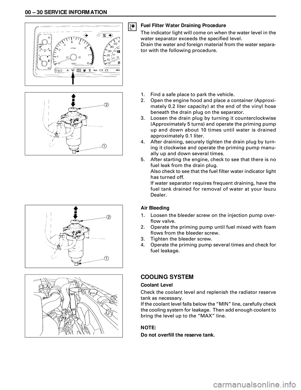
Fuel Filter Water Draining Procedure
The indicator light will come on when the water level in the
water separator exceeds the specified level.
Drain the water and foreign material from the water separa-
tor with the following procedure.
1. Find a safe place to park the vehicle.
2. Open the engine hood and place a container (Approxi-
mately 0.2 liter capacity) at the end of the vinyl hose
beneath the drain plug on the separator.
3. Loosen the drain plug by turning it counterclockwise
(Approximately 5 turns) and operate the priming pump
up and down about 10 times until water is drained
approximately 0.1 liter.
4. After draining, securely tighten the drain plug by turn-
ing it clockwise and operate the priming pump manu-
ally up and down several times.
5. After starting the engine, check to see that there is no
fuel leak from the drain plug.
Also check to see that the fuel filter water indicator light
has turned off.
If water separator requires frequent draining, have the
fuel tank drained for removal of water at your Isuzu
Dealer.
Air Bleeding
1. Loosen the bleeder screw on the injection pump over-
flow valve.
2. Operate the priming pump until fuel mixed with foam
flows from the bleeder screw.
3. Tighten the bleeder screw.
4. Operate the priming pump several times and check for
fuel leakage.
COOLING SYSTEM
Coolant Level
Check the coolant level and replenish the radiator reserve
tank as necessary.
If the coolant level falls below the ÒMINÓ line, carefully check
the cooling system for leakage. Then add enough coolant to
bring the level up to the ÒMAXÓ line.
NOTE:
Do not overfill the reserve tank.
Page 1531 of 3573
SERVICE INFORMATION 00 Ð 31
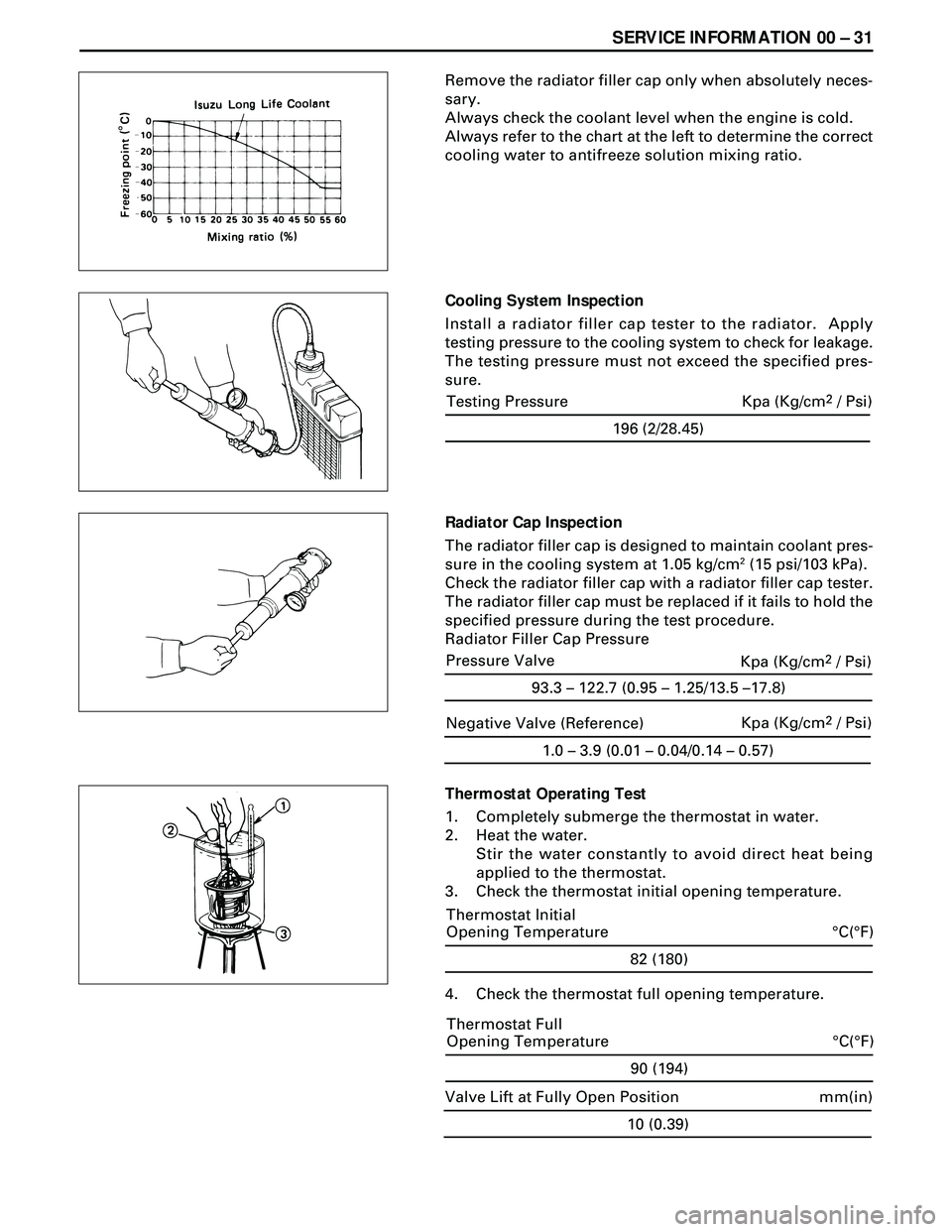
Remove the radiator filler cap only when absolutely neces-
sary.
Always check the coolant level when the engine is cold.
Always refer to the chart at the left to determine the correct
cooling water to antifreeze solution mixing ratio.
Cooling System Inspection
Install a radiator filler cap tester to the radiator. Apply
testing pressure to the cooling system to check for leakage.
The testing pressure must not exceed the specified pres-
sure.
Radiator Cap Inspection
The radiator filler cap is designed to maintain coolant pres-
sure in the cooling system at 1.05 kg/cm
2 (15 psi/103 kPa).
Check the radiator filler cap with a radiator filler cap tester.
The radiator filler cap must be replaced if it fails to hold the
specified pressure during the test procedure.
Radiator Filler Cap Pressure
Thermostat Operating Test
1. Completely submerge the thermostat in water.
2. Heat the water.
Stir the water constantly to avoid direct heat being
applied to the thermostat.
3. Check the thermostat initial opening temperature.
82 (180)
°C(°F) Thermostat Initial
Opening Temperature
4. Check the thermostat full opening temperature.
1.0 – 3.9 (0.01 – 0.04/0.14 – 0.57)
Negative Valve (Reference)Kpa (Kg/cm2 / Psi)
90 (194)
°C(°F) Thermostat Full
Opening Temperature
10 (0.39)
mm(in) Valve Lift at Fully Open Position
196 (2/28.45)
Testing Pressure Kpa (Kg/cm2 / Psi)
93.3 – 122.7 (0.95 – 1.25/13.5 –17.8)
Pressure Valve
Kpa (Kg/cm2 / Psi)
Page 1576 of 3573
6A Ð 26 ENGINE MECHANICAL
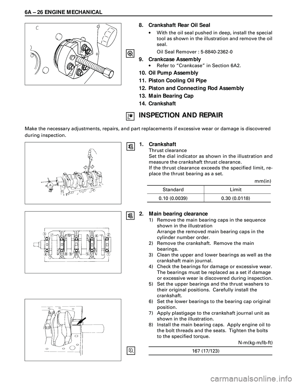
8. Crankshaft Rear Oil Seal
·With the oil seal pushed in deep, install the special
tool as shown in the illustration and remove the oil
seal.
Oil Seal Remover : 5-8840-2362-0
9. Crankcase Assembly
·Refer to ÒCrankcaseÓ in Section 6A2.
10. Oil Pump Assembly
11. Piston Cooling Oil Pipe
12. Piston and Connecting Rod Assembly
13. Main Bearing Cap
14. Crankshaft
INSPECTION AND REPAIR
Make the necessary adjustments, repairs, and part replacements if excessive wear or damage is discovered
during inspection.
1. Crankshaft
Thrust clearance
Set the dial indicator as shown in the illustration and
measure the crankshaft thrust clearance.
If the thrust clearance exceeds the specified limit, re-
place the thrust bearing as a set.
Standard Limit
mm(in)
0.10 (0.0039) 0.30 (0.0118)
167 (17/123)N·m(kg·m/lb·ft)
2. Main bearing clearance
1) Remove the main bearing caps in the sequence
shown in the illustration
Arrange the removed main bearing caps in the
cylinder number order.
2) Remove the crankshaft. Remove the main
bearings.
3) Clean the upper and lower bearings as well as the
crankshaft main journal.
4) Check the bearings for damage or excessive wear.
The bearings must be replaced as a set if damage
or excessive wear is discovered during inspection.
5) Set the upper bearings and the thrust washers to
their original positions. Carefully install the
crankshaft.
6) Set the lower bearings to the bearing cap original
position.
7) Apply plastigage to the crankshaft journal unit as
shown in the illustration.
8) Install the main bearing caps. Apply engine oil to
the bolt threads and the seats. Tighten the bolts
to the specified torque.
Page 1581 of 3573
ENGINE MECHANICAL 6A Ð 31
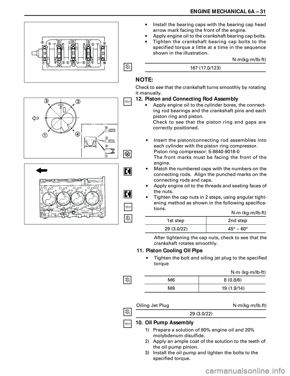
·Install the bearing caps with the bearing cap head
arrow mark facing the front of the engine.
·Apply engine oil to the crankshaft bearing cap bolts.
·Tighten the crankshaft bearing cap bolts to the
specified torque a little at a time in the sequence
shown in the illustration.
NOTE:
Check to see that the crankshaft turns smoothly by rotating
it manually.
12. Piston and Connecting Rod Assembly
·Apply engine oil to the cylinder bores, the connect-
ing rod bearings and the crankshaft pins and each
piston ring and piston.
Check to see that the piston ring end gaps are
correctly positioned.
29 (3.0/22)
N·m(kg·m/lb.ft) Oiling Jet Plug
10. Oil Pump Assembly
1) Prepare a solution of 80% engine oil and 20%
molybdenum disulfide.
2) Apply an ample coat of the solution to the teeth of
the oil pump pinion.
3) Install the oil pump and tighten the bolts to the
specified torque.After tightening the cap nuts, check to see that the
crankshaft rotates smoothly.
11. Piston Cooling Oil Pipe
·Tighten the bolt and oiling jet plug to the specified
torque ·Insert the piston/connecting rod assemblies into
each cylinder with the piston ring compressor.
Piston ring compressor: 5-8840-9018-0
The front marks must be facing the front of the
engine.
·Match the numbered caps with the numbers on the
connecting rods. Align the punched marks on the
connecting rods and caps.
·Apply engine oil to the threads and seating faces of
the nuts.
·Tighten the cap nuts in 2 steps, using angular tight-
ening method as shown in the following specifica-
tions.
167 (17.0/123)N·m(kg·m/lb·ft)
N·m (kg·m/lb·ft)
45¡ ~ 60¡ 1st step 2nd step
29 (3.0/22)
N·m (kg·m/lb·ft)
19 (1.9/14) M6 8 (0.8/6)
M8
Page 1593 of 3573
ENGINE MECHANICAL 6A Ð 43
8. Camshaft Timing Gear
9. Camshaft Thrust Plate
10. Camshaft
11. Crankshaft Front Oil Seal
·With the oil seal pushed in deep, install the special
tool as shown in the illustration and remove the oil
seal.
Oil Seal Remover : 5-8840-2362-0
12. Timing Gear Case
13. Tappet
14. Piston Assembly
15. Main Bearing Cap Assembly
16. Crankshaft
17. Piston Cooling Oil Pipe
18. Cylinder Block
Page 1595 of 3573
ENGINE MECHANICAL 6A Ð 45
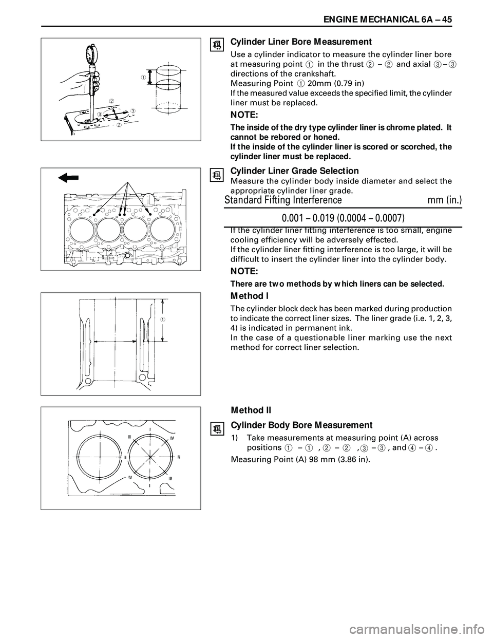
Cylinder Liner Bore Measurement
Use a cylinder indicator to measure the cylinder liner bore
at measuring point in the thrust Ð and axial Ð
directions of the crankshaft.
Measuring Point 20mm (0.79 in)
If the measured value exceeds the specified limit, the cylinder
liner must be replaced.
NOTE:
The inside of the dry type cylinder liner is chrome plated. It
cannot be rebored or honed.
If the inside of the cylinder liner is scored or scorched, the
cylinder liner must be replaced.
Cylinder Liner Grade Selection
Measure the cylinder body inside diameter and select the
appropriate cylinder liner grade.
If the cylinder liner fitting interference is too small, engine
cooling efficiency will be adversely effected.
If the cylinder liner fitting interference is too large, it will be
difficult to insert the cylinder liner into the cylinder body.
NOTE:
There are two methods by which liners can be selected.
Method I
The cylinder block deck has been marked during production
to indicate the correct liner sizes. The liner grade (i.e. 1, 2, 3,
4) is indicated in permanent ink.
In the case of a questionable liner marking use the next
method for correct liner selection.
Method II
Cylinder Body Bore Measurement
1) Take measurements at measuring point (A) across
positions Ð , Ð , Ð , and Ð .
Measuring Point (A) 98 mm (3.86 in).
12233
1
112
2334
4
0.001 – 0.019 (0.0004 – 0.0007)
mm (in.) Standard Fifting Interference
Page 1597 of 3573
ENGINE MECHANICAL 6A Ð 47
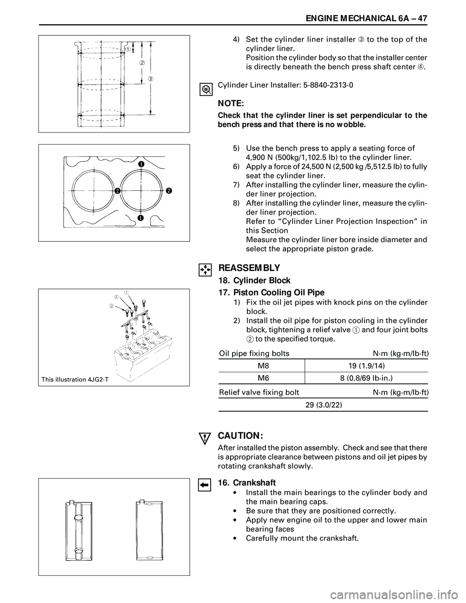
4) Set the cylinder liner installer  to the top of the
cylinder liner.
Position the cylinder body so that the installer center
is directly beneath the bench press shaft center Ã.
Cylinder Liner Installer: 5-8840-2313-0
NOTE:
Check that the cylinder liner is set perpendicular to the
bench press and that there is no wobble.
5) Use the bench press to apply a seating force of
4,900 N (500kg/1,102.5 lb) to the cylinder liner.
6) Apply a force of 24,500 N (2,500 kg /5,512.5 lb) to fully
seat the cylinder liner.
7) After installing the cylinder liner, measure the cylin-
der liner projection.
8) After installing the cylinder liner, measure the cylin-
der liner projection.
Refer to ÒCylinder Liner Projection InspectionÓ in
this Section
Measure the cylinder liner bore inside diameter and
select the appropriate piston grade.
CAUTION:
After installed the piston assembly. Check and see that there
is appropriate clearance between pistons and oil jet pipes by
rotating crankshaft slowly.
16. Crankshaft
·Install the main bearings to the cylinder body and
the main bearing caps.
·Be sure that they are positioned correctly.
·Apply new engine oil to the upper and lower main
bearing faces
·Carefully mount the crankshaft.
This illustration 4JG2-T
REASSEMBLY
18. Cylinder Block
17. Piston Cooling Oil Pipe
1) Fix the oil jet pipes with knock pins on the cylinder
block.
2) Install the oil pipe for piston cooling in the cylinder
block, tightening a relief valve 1 and four joint bolts
2 to the specified torque.
Relief valve fixing bolt
29 (3.0/22)
Oil pipe fixing bolts
19 (1.9/14)
8 (0.8/69 lb·in.) M8
M6N·m (kg·m/lb·ft)
N·m (kg·m/lb·ft)