Page 1666 of 3573
6B Ð 12 ENGINE COOLING
TENSION ADJUSTMENT
P/S oil pump and A/C compressor pulley belt.
·With P/S pump lock bolt loose, adjust belt tension
with adjust belt.
Cooling fan pulley belt
·With AC Generator mounting and lock bolts loose,
adjust belt tension with adjuster's adjust bolt.
AC generator fixing bolt40 (4.1/30) Torque StandardN·m(Kg·m/lb·ft)
Adjust plate fixing bolt24 (2.4/17)
Adjust plate lock bolt19 (1.9/14)
P/S oil pump adjustor lock bolt37 (3.8/27)
Page 1681 of 3573
FUEL SYSTEM 6C Ð 15
REMOVAL
Preparation:
·Disconnect battery ground cable.
·Drain coolant.
1. Air Cleaner Cover & Air Duct
2. Intercooler Assembly (4JG2-T ONLY)
· Refer to Intercooler Assembly removal.
3. Radiator Assembly
·Disconnect upper and lower hoses on the engine
side.
4. Cooling Fan Assembly
·Remove cooling fan asm and remove fan pulley
and spacer.
5. P/S Pump Drive Belt
·Loosen P/S pump lock bolt and adjust bolt remove
two drive belts.
6. AC Generator Drive Belt
·Loosen AC generator mounting bolt (under side)
and adjust, bolt and remove drive belt.
7. Timing Gear
·Refer to Timing Gear Removal
·Remove the loosened nut and fixing bolt and
remove the timing gear.
8.Fuel Filter Assembly
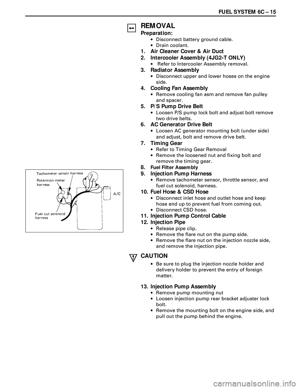
9. Injection Pump Harness
·Remove tachometer sensor, throttle sensor, and
fuel cut solenoid, harness.
10. Fuel Hose & CSD Hose
·Disconnect inlet hose and outlet hose and keep
hose end up to prevent fuel from coming out.
·Disconnect CSD hose.
11. Injection Pump Control Cable
12. Injection Pipe
·Release pipe clip.
·Remove the flare nut on the pump side.
·Remove the flare nut on the injection nozzle side,
and remove the injection pipe.
CAUTION
·Be sure to plug the injection nozzle holder and
delivery holder to prevent the entry of foreign
matter.
13. Injection Pump Assembly
·Remove pump mounting nut
·Loosen injection pump rear bracket adjuster lock
bolt.
·Remove the mounting bolt on the engine side, and
pull out the pump behind the engine.
Page 1682 of 3573
6C Ð 16 FUEL SYSTEM
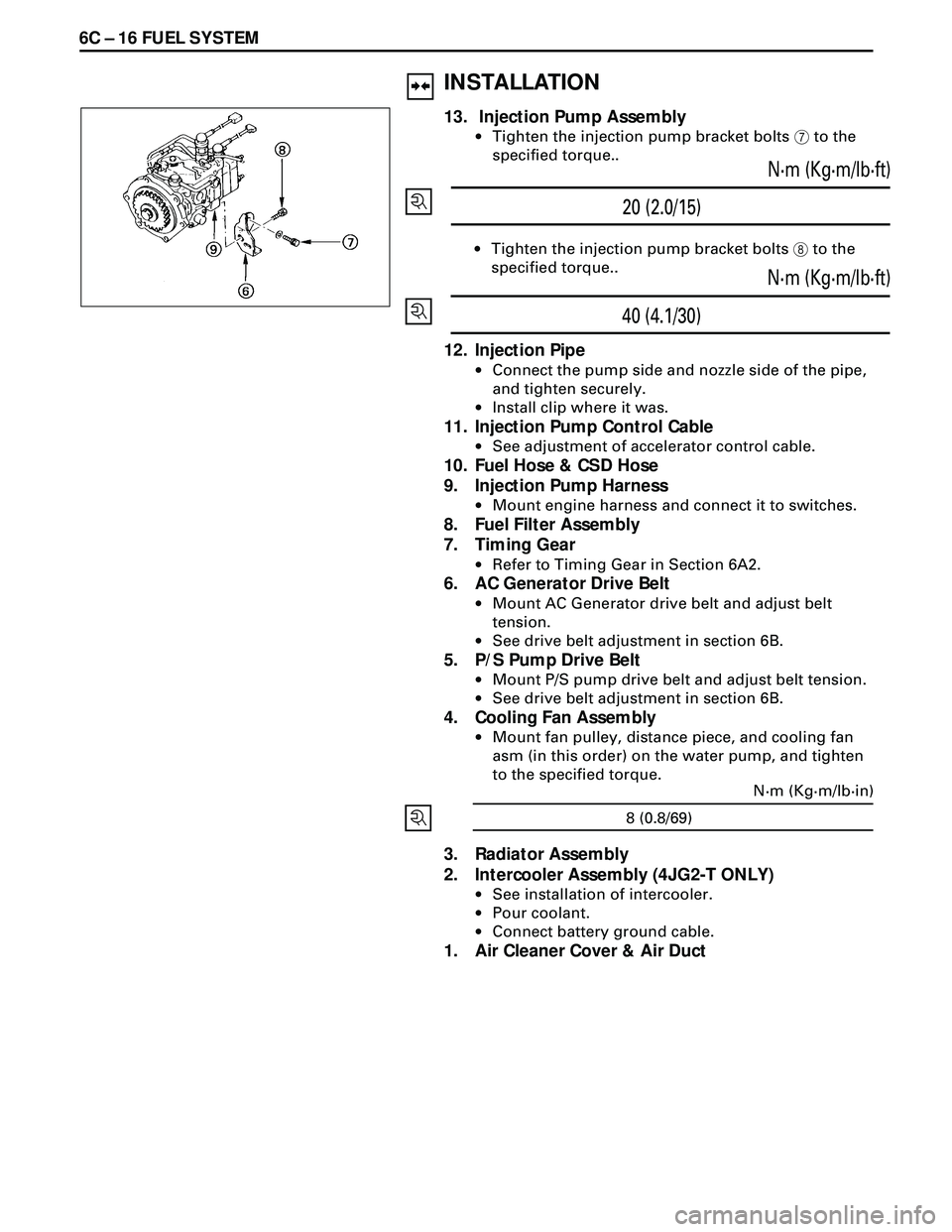
20 (2.0/15)N·m (Kg·m/lb·ft)
·Tighten the injection pump bracket bolts 8 to the
specified torque..
40 (4.1/30)N·m (Kg·m/lb·ft)
12. Injection Pipe
·Connect the pump side and nozzle side of the pipe,
and tighten securely.
·Install clip where it was.
11. Injection Pump Control Cable
·See adjustment of accelerator control cable.
10. Fuel Hose & CSD Hose
9. Injection Pump Harness
·Mount engine harness and connect it to switches.
8. Fuel Filter Assembly
7. Timing Gear
·Refer to Timing Gear in Section 6A2.
6. AC Generator Drive Belt
·Mount AC Generator drive belt and adjust belt
tension.
·See drive belt adjustment in section 6B.
5. P/S Pump Drive Belt
·Mount P/S pump drive belt and adjust belt tension.
·See drive belt adjustment in section 6B.
4. Cooling Fan Assembly
·Mount fan pulley, distance piece, and cooling fan
asm (in this order) on the water pump, and tighten
to the specified torque.
3. Radiator Assembly
2. Intercooler Assembly (4JG2-T ONLY)
·See installation of intercooler.
·Pour coolant.
·Connect battery ground cable.
1. Air Cleaner Cover & Air Duct
INSTALLATION
13. Injection Pump Assembly
·Tighten the injection pump bracket bolts 7 to the
specified torque..
8 (0.8/69)N·m (Kg·m/lb·in)
Page 1736 of 3573
ENGINE MECHANICAL 6A – 3
SERVICE INFORMATION
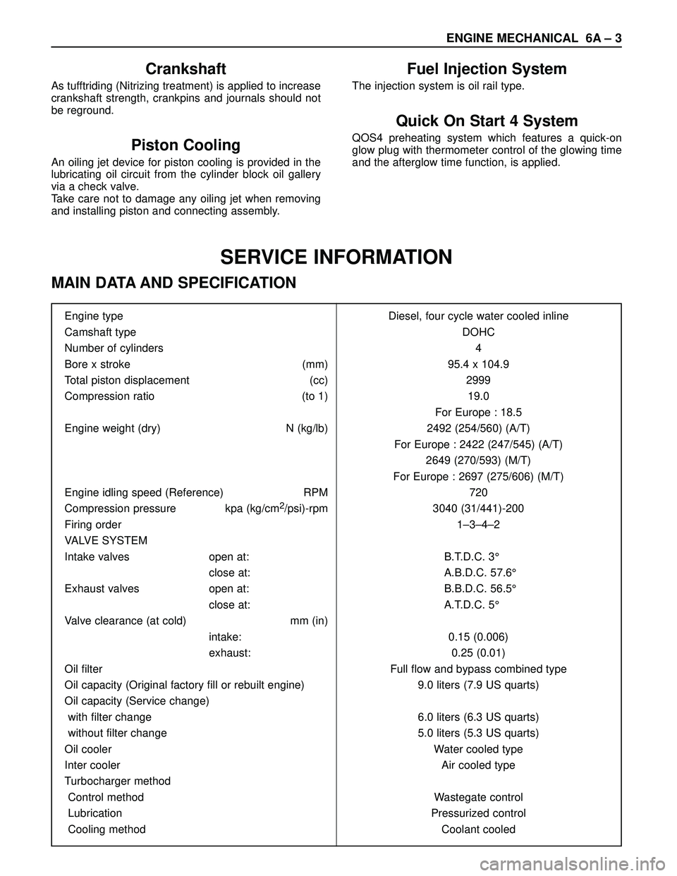
MAIN DATA AND SPECIFICATION
Engine type Diesel, four cycle water cooled inline
Camshaft type DOHC
Number of cylinders 4
Bore x stroke (mm) 95.4 x 104.9
Total piston displacement (cc) 2999
Compression ratio (to 1) 19.0
For Europe : 18.5
Engine weight (dry) N (kg/lb) 2492 (254/560) (A/T)
For Europe : 2422 (247/545) (A/T)
2649 (270/593) (M/T)
For Europe : 2697 (275/606) (M/T)
Engine idling speed (Reference) RPM 720
Compression pressure kpa (kg/cm
2/psi)-rpm 3040 (31/441)-200
Firing order 1–3–4–2
VALVE SYSTEM
Intake valves open at: B.T.D.C. 3°
close at: A.B.D.C. 57.6°
Exhaust valves open at: B.B.D.C. 56.5°
close at: A.T.D.C. 5°
Valve clearance (at cold) mm (in)
intake: 0.15 (0.006)
exhaust: 0.25 (0.01)
Oil filter Full flow and bypass combined type
Oil capacity (Original factory fill or rebuilt engine) 9.0 liters (7.9 US quarts)
Oil capacity (Service change)
with filter change 6.0 liters (6.3 US quarts)
without filter change 5.0 liters (5.3 US quarts)
Oil cooler Water cooled type
Inter cooler Air cooled type
Turbocharger method
Control method Wastegate control
Lubrication Pressurized control
Cooling method Coolant cooled
Crankshaft
As tufftriding (Nitrizing treatment) is applied to increase
crankshaft strength, crankpins and journals should not
be reground.
Piston Cooling
An oiling jet device for piston cooling is provided in the
lubricating oil circuit from the cylinder block oil gallery
via a check valve.
Take care not to damage any oiling jet when removing
and installing piston and connecting assembly.
Fuel Injection System
The injection system is oil rail type.
Quick On Start 4 System
QOS4 preheating system which features a quick-on
glow plug with thermometer control of the glowing time
and the afterglow time function, is applied.
Page 1737 of 3573
6A – 4 ENGINE MECHANICAL
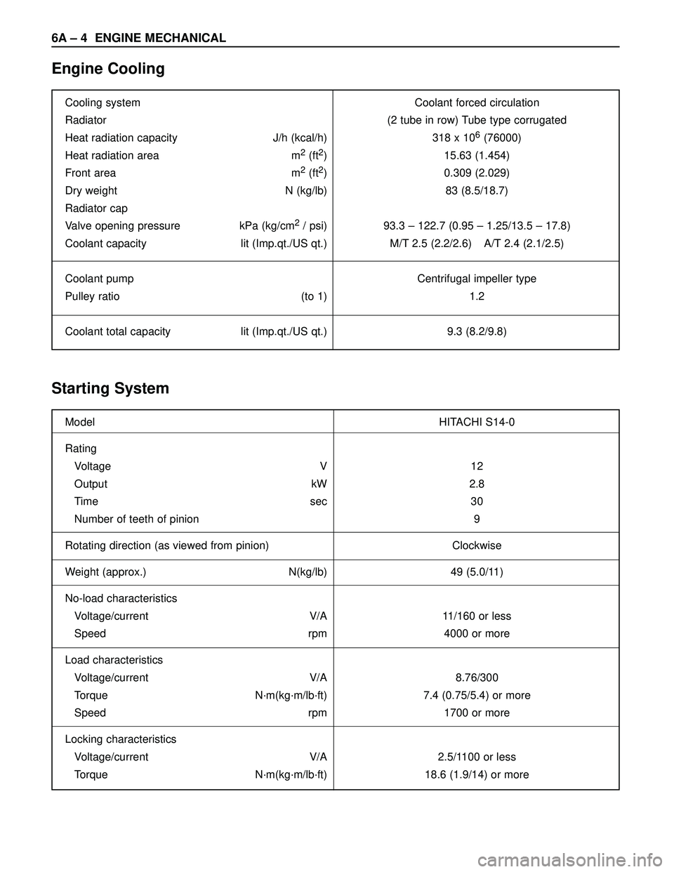
Engine Cooling
Starting System
Cooling system Coolant forced circulation
Radiator (2 tube in row) Tube type corrugated
Heat radiation capacity J/h (kcal/h) 318 x 10
6(76000)
Heat radiation area m
2(ft2) 15.63 (1.454)
Front area m
2(ft2) 0.309 (2.029)
Dry weight N (kg/lb) 83 (8.5/18.7)
Radiator cap
Valve opening pressure kPa (kg/cm
2/ psi) 93.3 – 122.7 (0.95 – 1.25/13.5 – 17.8)
Coolant capacity lit (Imp.qt./US qt.) M/T 2.5 (2.2/2.6) A/T 2.4 (2.1/2.5)
Coolant pump Centrifugal impeller type
Pulley ratio (to 1) 1.2
Coolant total capacity lit (Imp.qt./US qt.) 9.3 (8.2/9.8)
Model HITACHI S14-0
Rating
Voltage V 12
Output kW 2.8
Time sec 30
Number of teeth of pinion 9
Rotating direction (as viewed from pinion) Clockwise
Weight (approx.) N(kg/lb) 49 (5.0/11)
No-load characteristics
Voltage/current V/A 11/160 or less
Speed rpm 4000 or more
Load characteristics
Voltage/current V/A 8.76/300
Torque N·m(kg·m/lb·ft) 7.4 (0.75/5.4) or more
Speed rpm 1700 or more
Locking characteristics
Voltage/current V/A 2.5/1100 or less
Torque N·m(kg·m/lb·ft) 18.6 (1.9/14) or more
Page 1741 of 3573
6A – 8 ENGINE MECHANICAL
Parts Items Service standard Service limit Remarks
Cylinder
Block—
95.421 – 95.450
(3.7567 – 3.7579)0.20 (0.0079) Warpage
(Upper surface of the cylinder block)
Cylinder bore diameter
Parts Items Service standard Service limit Remarks
Thermostat
Radiator cap83 – 87°C
(181 – 189°F)
More than 9.5 (0.374)
at 100°C (212°F)
88.2 – 117.6 kPa
(12.8 –17.0 psi) Valve opening temperature
Valve full open temperature and lift
Valve opening pressure
Engine Coolingmm (in) mm (in)
Page 1743 of 3573
6A – 10 ENGINE MECHANICAL
8. Check the engine oil level and replenish to the
specified level if required.
9. Start the engine and check for oil leakage from the
main oil filter.
FUEL SYSTEM
Fuel filter
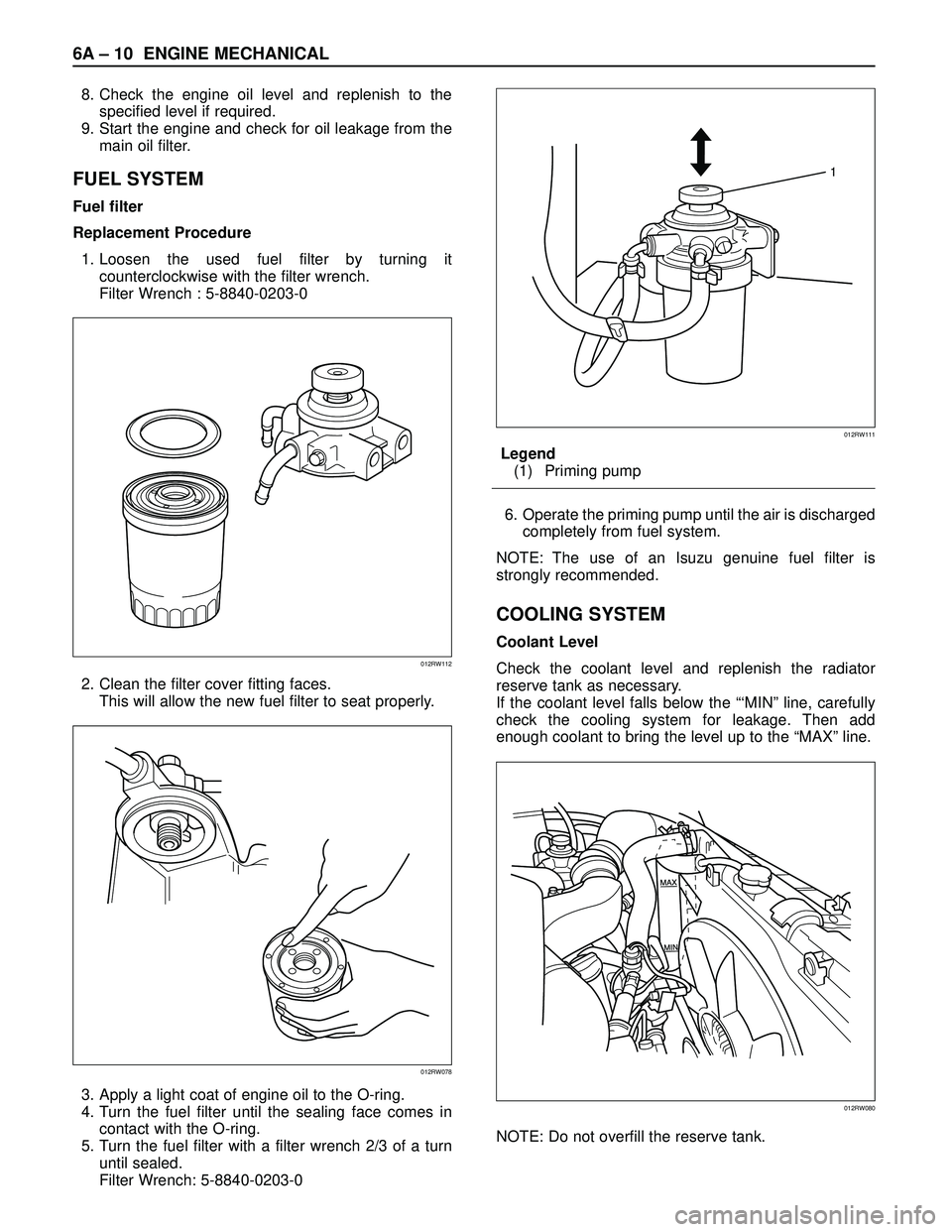
Replacement Procedure
1. Loosen the used fuel filter by turning it
counterclockwise with the filter wrench.
Filter Wrench : 5-8840-0203-0
2. Clean the filter cover fitting faces.
This will allow the new fuel filter to seat properly.
3. Apply a light coat of engine oil to the O-ring.
4. Turn the fuel filter until the sealing face comes in
contact with the O-ring.
5. Turn the fuel filter with a filter wrench 2/3 of a turn
until sealed.
Filter Wrench: 5-8840-0203-0Legend
(1) Priming pump
6. Operate the priming pump until the air is discharged
completely from fuel system.
NOTE: The use of an Isuzu genuine fuel filter is
strongly recommended.
COOLING SYSTEM
Coolant Level
Check the coolant level and replenish the radiator
reserve tank as necessary.
If the coolant level falls below the “‘MIN” line, carefully
check the cooling system for leakage. Then add
enough coolant to bring the level up to the “MAX” line.
NOTE: Do not overfill the reserve tank.
012RW112
012RW078
1
012RW111
012RW080
Page 1744 of 3573
ENGINE MECHANICAL 6A – 11
Remove the radiator filler cap only when absolutely
necessary.
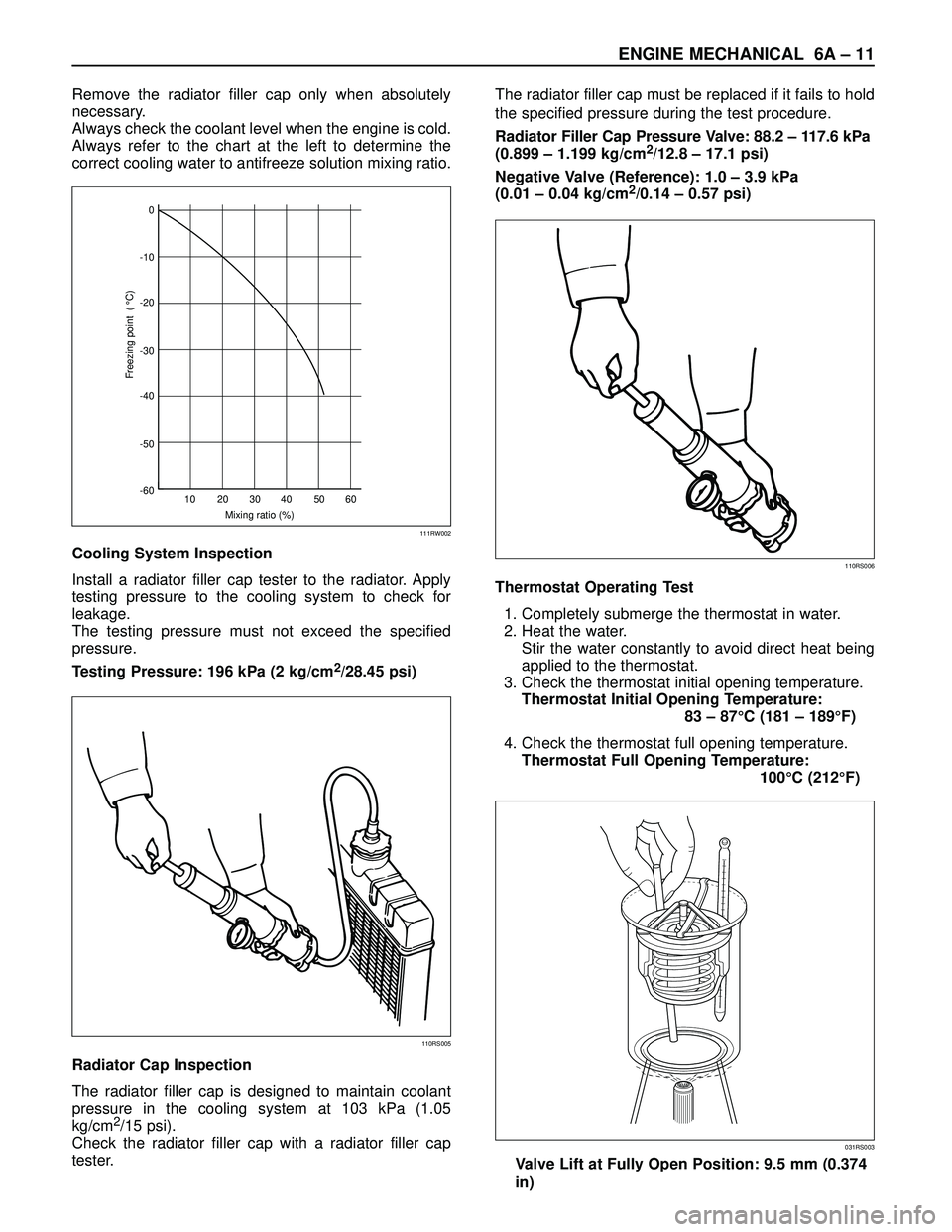
Always check the coolant level when the engine is cold.
Always refer to the chart at the left to determine the
correct cooling water to antifreeze solution mixing ratio.
Cooling System Inspection
Install a radiator filler cap tester to the radiator. Apply
testing pressure to the cooling system to check for
leakage.
The testing pressure must not exceed the specified
pressure.
Testing Pressure: 196 kPa (2 kg/cm
2/28.45 psi)
Radiator Cap Inspection
The radiator filler cap is designed to maintain coolant
pressure in the cooling system at 103 kPa (1.05
kg/cm
2/15 psi).
Check the radiator filler cap with a radiator filler cap
tester.The radiator filler cap must be replaced if it fails to hold
the specified pressure during the test procedure.
Radiator Filler Cap Pressure Valve: 88.2 – 117.6 kPa
(0.899 – 1.199 kg/cm
2/12.8 – 17.1 psi)
Negative Valve (Reference): 1.0 – 3.9 kPa
(0.01 – 0.04 kg/cm
2/0.14 – 0.57 psi)
Thermostat Operating Test
1. Completely submerge the thermostat in water.
2. Heat the water.
Stir the water constantly to avoid direct heat being
applied to the thermostat.
3. Check the thermostat initial opening temperature.
Thermostat Initial Opening Temperature:
83 – 87°C (181 – 189°F)
4. Check the thermostat full opening temperature.
Thermostat Full Opening Temperature:
100°C (212°F)
Valve Lift at Fully Open Position: 9.5 mm (0.374
in)0
-10
-20
-30
-40
-50
-60
10 20 30
Mixing ratio (%)
Freezing point ( °C)
40 50 60
111RW002
110RS005
110RS006
031RS003