Page 2367 of 3573
 and a
press, install the mainshaft center bearing.
NOTE: Center bearing snap ring gro")
MANUAL TRANSMISSION7B±49
13. Install the mainshaft center bearing.
1. Using installer 5±8840±2555±0 (J±42799) and a
press, install the mainshaft center bearing.
NOTE: Center bearing snap ring groove toward rear.
226RW195
2. Using a thickness gauge, measure 1st gear thrust
clearance.
Standard: 0.10 ± 0.45mm (0.004 ± 0.018 in)
226RW118
14. Install the 5th gear.
1. Using installer 5±8840±2555±0 (J±42799) and a
press, install the 5th gear.
2. Select a snap ring that will allow minimum axial
play.Mark
Thickness
C2.75 ± 2.80 mm (0.108 ± 0.110 in)
D2.80 ± 2.85 mm (0.110 ± 0.112 in)
E2.85 ± 2.90 mm (0.112 ± 0.114 in)
F2.90 ± 2.95 mm (0.114 ± 0.116 in)
G2.95 ± 3.00 mm (0.116 ± 0.118 in)
H3.00 ± 3.05 mm (0.118 ± 0.120 in)
J3.05 ± 3.10 mm (0.120 ± 0.122 in)
K3.10 ± 3.15 mm (0.122 ± 0.124 in)
L3.15 ± 3.20 mm (0.124 ± 0.126 in)
M3.20 ± 3.25 mm (0.126 ± 0.128 in)
N3.25 ± 3.30 mm (0.128 ± 0.130 in)
P3.30 ± 3.35 mm (0.130 ± 0.132 in)
226RW203
3. Using a screwdriver and hammer, install the new
snap ring.
226RW127
Page 2376 of 3573
7B±58MANUAL TRANSMISSION
26. Install the top gear shaft.
1. Align the projection of the hub No.2 with the
synchronizer ring slots, and install the top gear
shaft assembly to the mainshaft.
2. Check that the gear rotates smoothly.
226RW006
27. Install the counter gear shaft.
1. Temporarily install the counter gear shaft to the
intermediate plate.
226RW028
2. Using installer 5±8840±2552±0 (J±42796) and a
hammer, drive in the center bearing as shown.
NOTE: Outer race snap ring groove toward rear.
226RW192Reference: Drive in the counter rear bearing
by tapping on the front end of the counter
shaft.
226RW022
Page 2377 of 3573
MANUAL TRANSMISSION7B±59
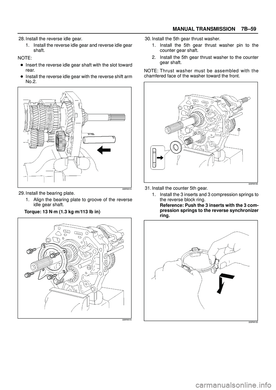
28. Install the reverse idle gear.
1. Install the reverse idle gear and reverse idle gear
shaft.
NOTE:
�Insert the reverse idle gear shaft with the slot toward
rear.
�Install the reverse idle gear with the reverse shift arm
No.2.
226RW019
29. Install the bearing plate.
1. Align the bearing plate to groove of the reverse
idle gear shaft.
Torque: 13 N´m (1.3 kg´m/113 lb in)
226RW016
30. Install the 5th gear thrust washer.
1. Install the 5th gear thrust washer pin to the
counter gear shaft.
2. Install the 5th gear thrust washer to the counter
gear shaft.
NOTE: Thrust washer must be assembled with the
chamfered face of the washer toward the front.
226RW185
31. Install the counter 5th gear.
1. Install the 3 inserts and 3 compression springs to
the reverse block ring.
Reference: Push the 3 inserts with the 3 com-
pression springs to the reverse synchronizer
ring.
226RW120
Page 2550 of 3573
LIGHTING SYSTEM8A–11
Side Turn Signal Light Bulb
Removal
1. Disconnect the battery ground cable.
2. Pull the light/bulb(1) toward you while pushing the
light housing in the rear direction of the vehicle to
release its lock.
3. Remove the bulb by turning it counterclockwise while
pushing it at the same time.
801RW013
Installation
To install, follow the removal steps in the reverse order.
Rear Turn Signal Light Bulb
Removal
1. Disconnect the battery ground cable.
2. Remove the three screws and release the lock at two
positions.
3. Remove the rear combination light(3).
4. Remove the turn signal light socket/bulb(1) by turning
it counterclockwise.
5. Remove the bulb(2) by turning it counterclockwise
while pushing it at the same time.
803RS002
Installation
To install, follow the removal steps in the reverse order.
Page 2597 of 3573

8DÐ4 WIRING SYSTEM
The chassis electrical system is a 12Ðvolt system with a
negative ground polarity.
Wire size are appropriate to respective circuits, and
classified by color. (The classification of harnesses by
color is shown on the circuit diagram for ease of harness
identification.)
The wire size is determined by load capacity and the
length of wire required.
The vehicle harnesses are: body harness, chassis
harness, engine room harness, instrument harness,
transmission harness, engine ECGI harness, dome light
harness, door harness, rear body harness, tailgate
harness, SRS harness and battery cables.
The harnesses are protected either by tape or corrugated
tube, depending on harness location.
The circuit for each system consists of the power source,
wire, fuse, relay, switch, load parts and ground, all of
which are shown on the circuit diagram.
In this section, each electrical device is classified by
system.
For major parts shown on the circuit based on the circuit
diagram for each system, a summary, diagnosis of
troubles and inspection procedures are detailed.
Notes for Working on Electrical
Items
Disconnecting the Battery Cable
1. All switches should be in the ÒOFFÓ position.
2. Disconnect the battery ground cable (2).
3. Disconnect the battery positive cable (1).
CAUTION: It is important that the battery ground
cable be disconnected first. Disconnecting the
battery positive cable first can result in a short circuit.
Connecting the Battery Cable
Follow the disconnecting procedure in the reverse order.CAUTION: Clean the battery terminal and apply a
light coat of grease to prevent terminal corrosion.
Disconnecting the Connector
Some connectors have a tang lock to hold the connectors
together during vehicle operation.
Some tang locks are released by pulling them towards
you (1).
Other tang locks are released by pressing them forward
(2).
Determine which type of tang lock is on the connector
being handled.
Firmly grasp both sides (male and female) of the
connector (3).
Release the tang lock and carefully pull the two halves of
the connector apart.
Never pull on the wires to separate the connectors (4).
2
1
General Description
1
2
3
4
Page 2599 of 3573
 into the
connector wire side of a waterproof connector.
Use one side of a connector (1) with its wi")
8DÐ6 WIRING SYSTEM
Waterproof Connector Inspection
It is not possible to insert the test probes (2) into the
connector wire side of a waterproof connector.
Use one side of a connector (1) with its wires cut to make
the test. Connect the test connector to the connector to
be tested (3). Connect the test probes to the cut wires to
check the connector continuity.
Connector Pin Removal Ð Connector
Housing Tang Lock Type
1. Insert a slender shaft (1) into the connector housing
open end (5).
2. Push the tang lock (2) up (in the direction of the arrow
in the illustration).
Pull the wire (3) with pin (4) free from the wire side of
the connector.
Connector Pin Removal Ð Pin Tang Lock
Type
1. Insert a slender shaft (1) into the connector housing
open end (5).
2. Push the tang lock (2) flat (toward the wire (3) side of
the connector.
Pull the wire with pin (4) free from the wire side of the
connector.
Connector Pin Insertion
1. Check that the tang lock (1) is fully up.
2. Insert the pin (3) from the connector wire (2) side.
Push the pin in until the tang lock closes firmly.
3. Gently pull on the wires to make sure that the
connector pin is firmly set in place.
1
3
21
2
3
5
4
1
2
3
4 51
2
3
Page 3245 of 3573
, 1 fixing bolt (3), and
1 clip (4). Pull out")
8F±50BODY STRUCTURE
7. Remove instrument panel driver lower cover
assembly.
�Remove the engine hood opener fixing screws.
�Remove the 2 fixing screws (2), 1 fixing bolt (3), and
1 clip (4). Pull out the fasteners at the 4 positions
(1).
740RW105
8. Remove driver knee bolster assembly (W/SRS).
�Remove the 6 fixing nuts.
740RW122
9. Remove front defroster grille.
�Pry 8 claws on the front side toward you side (room
side) and raise the grille upward.
10. Remove instrument panel assembly.
�Remove the 2 fixing bolts on the SRS adjust bracket
and the cross beam under the passenger inflator
module (W/SRS).
CAUTION: F o r p recautions on installation or
removal of SRS Ð air bag system, refer to
Supplemental RestraintSystem (SRS) Ð AIR BAG in
Restraint section.
827RW031
�Disconnect the 3 air conditioner control cables on
the unit side.
�Remove the instrument harness connectors (5
connectors on the drivers side and 3 connectors on
the passenger side), the passenger inflator module
connector, the radio antenna cable plug, and the
ground cable fixing bolt on the center bracket.
�Remove the 4 bolts (4) and the 2 nuts (3) under the
instrument panel assembly, and the upper left and
the upper right bolts (2) and the center nut (1).
Page 3246 of 3573
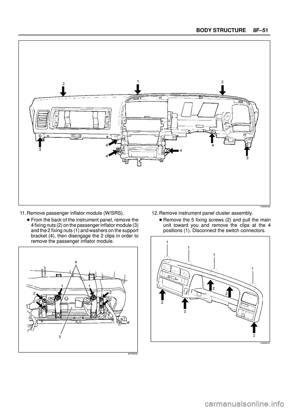
8F±51 BODY STRUCTURE
740RW106
11. Remove passenger inflator module (W/SRS).
�From the back of the instrument panel, remove the
4 fixing nuts (2) on the passenger inflator module (3)
and the 2 fixing nuts (1) and washers on the support
bracket (4), then disengage the 2 clips in order to
remove the passenger inflator module.
827RW032
12. Remove instrument panel cluster assembly.
�Remove the 5 fixing screws (2) and pull the main
unit toward you and remove the clips at the 4
positions (1). Disconnect the switch connectors.
740RW107

 toward you while pushing the
light housing in the rear direction of the v")