Page 668 of 3573
4C±2
DRIVE SHAFT SYSTEM
Service Precaution
WARNING: I F S O E Q U IPPED WITH A
SUPPLEMENTAL RESTRAINT SYSTEM (SRS),
REFER TO THE SRS COMPONENT AND WIRING
LOCATION VIEW IN ORDER TO DETERMINE
WHETHER YOU ARE PERFORMING SERVICE ON OR
NEAR THE SRS COMPONENTS OR THE SRS
WIRING. WHEN YOU ARE PERFORMING SERVICE
ON OR NEAR THE SRS COMPONENTS OR THE SRS
WIRING, REFER TO THE SRS SERVICE
INFORMATION. FAILURE TO FOLLOW WARNINGS
COULD RESULT IN POSSIBLE AIR BAG
DEPLOYMENT, PERSONAL INJURY, OR
OTHERWISE UNNEEDED SRS SYSTEM REPAIRS.
CAUTION: Always use the correct fastener in the
proper location. When you replace a fastener, use
ONLY the exact part number for that application.
ISUZU will call out those fasteners that require a
replacement after removal. ISUZU will also call out
the fasteners that require thread lockers or thread
sealant. UNLESS OTHERWISE SPECIFIED , do not
use supplemental coatings (Paints, greases, or other
corrosion inhibitors) on threaded fasteners or
fastener joint interfaces. Generally, such coatings
adversely affect the fastener torque and the joint
clamping force, and may damage the fastener. When
you install fasteners, use the correct tightening
sequence and specifications. Following these
instructions can help you avoid damage to parts and
systems.
General Description
This publication contains essential removal, installation,
adjustment and maintenance procedures.
The front axle utilizes a central disconnect type front
axle/transfer case system.
The drive axles are completely flexible assemblies,
consisting of inner and outer constant velocity (CV) drive
shaft joints connected by an axle shaft.
For description of propeller shaft and universal joint, refer
to Front/Rear Propeller Shaft in this section.
Page 669 of 3573
4C±3 DRIVE SHAFT SYSTEM
Diagnosis
ConditionPossible causeCorrection
Oil Leak At Front AxleWorn or defective oil seal.Replace the oil seal.
Front axle housing cracked.Repair or replace.
Oil Leak At Pinion ShaftToo much gear oil.Correct the oil level.
Oil seal worn or defective.Replace the oil seal.
Pinion flange loose or damaged.Tighten or replace.
Noises In Front Axle Drive Shaft
JointBroken or worn drive shaft joints and
bellows (BJ and DOJ).Replace the drive shaft joints and
bellows.
ªClankº When Accelerating From
ªCoastºLoose drive shaft joint to output shaft
bolts.Tighten.
Damaged inner drive shaft joint.Replace.
Shudder or Vibration During
Acceleration
Excessive drive shaft joint angle.Repair.
AccelerationWorn or damaged drive shaft joints.Replace.
Sticking spider assembly (inner drive
shaft joint).Lubricate or replace.
Sticking joint assembly (outer drive
shaft joint).Lubricate or replace.
Vibration At Highway SpeedsOut of balance or out of round tires.Balance or replace.
Front end out of alignment.Align.
Noises in Front AxleInsufficient gear oil.Replenish the gear oil.
Wrong or poor grade gear oil.Replace the gear oil.
Drive pinion to ring gear backlash
incorrect.Adjust the backlash.
Worn or chipped ring gear, pinion
gear or side gear.Replace the ring gear, pinion gear or
side gear.
Pinion shaft bearing worn.Replace the pinion shaft bearing.
Wheel bearing worn.Replace the wheel bearing.
Differential bearing loose or worn.Tighten or replace.
Wanders and PullsWheel bearing preload too tight.Adjust the wheel bearing preload.
Incorrect front alignment.Adjust the front alignment.
Steering linkage loose or worn.Tighten or replace.
Steering gear out of adjustment.Adjust or replace the steering gear.
Tire worn or improperly inflated.Adjust the inflation or replace.
Front or rear suspension parts loose
or broken.Tighten or replace.
Front Wheel ShimmyWheel bearing worn or improperly
adjusted.Adjust or replace.
Incorrect front alignment.Adjust the front alignment.
Worn ball joint or bush.Replace the ball joint or bush.
Steering linkage loose or worn.Tighten or replace.
Steering gear out of adjustment.Tighten or replace.
Tire worn or improperly inflated.Replace or adjust the inflation.
Shock absorber worn.Replace the shock absorber.
Page 675 of 3573
4C±9 DRIVE SHAFT SYSTEM
Front Hub and Disc (with Shift on the Fly)
Disassembled View
411RW001
Legend
(1) Bolt
(2) Cap
(3) Snap Ring and Shim
(4) Hub Flange
(5) Lock Washer and Lock Screw
(6) Hub Nut(7) Outer Bearing
(8) Bolt
(9) Hub and Disc Assembly
(10) Wheel Pin
(11) ABS Sensor Ring (If equipped)
(12) Inner Bearing
(13) Oil Seal
Disassembly
1. Before disassembly, select the 2WD position.
2. Jack up the front of vehicle and support frame with
jack stands.3. Remove the disc brake caliper assembly and hang it
on the frame with wires. Refer to Front Disc Brake
Caliper Assembly in Brakes section.
4. Remove bolt.
5. Remove cap.
6. Remove snap ring and shim.
7. Remove hub flange.
Page 678 of 3573

4C±12
DRIVE SHAFT SYSTEM
5. Apply grease (NLGI No.2 or equivalent) to the lip
portion, then install oil seal by using installer
5±8840±2120±0 and grip 5±8840±0007±0.
411RW008
6. Install ABS sensor ring, then tighten the bolts to the
specified torque.
Torque: 18 N´m (1.8 kg´m/13 lb ft)
7. Install hub and disc assembly.
�Apply grease in the hub.
�Apply wheel bearing type grease NLGI No. 2 or
equivalent to the outer and inner bearing.
Grease Amount
Hub: 35 g (1.23 oz)
Outer bearing: 10 g (0.35 oz)
Inner bearing: 15 g (0.53 oz)
411RS009
Legend
(1) Inner Bearing
(2) Hub
(3) Outer Bearing
8. Install hub nut. Turn the place where there is a
chamfer in the tapped hole to the outer side, then
attach the nut by using front hub nut wrench
5±8840±2117±0.
411RW005
Preload Adjustment
1. Tighten the hub nut to 29 N´m (3.0 kg´m/22 lb ft),
then fully loosen the nut.
2. Tighten the hub nut to the value given below,
using a spring scale on the wheel pin.
New bearing and New oil seal
Bearing Preload: 20 ± 25 N (2.0±2.5 kg/4.4 ±
5.5 lb)
Used bearing and New oil seal
Bearing Preload: 12 ± 18 N (1.2±1.8 kg/2.6 ±
4.0 lb)
If the measured bearing preload is outside the
specifications, adjust it by loosening or tightening the
bearing nut.
411RS011
Page 680 of 3573
4C±14
DRIVE SHAFT SYSTEM
Front Hub and Disc with Manual Locking Hub
Disassembled View
411RW009
Legend
(1) Bolt
(2) Cover Assembly
(3) Gasket
(4) Knob
(5) X±ring
(6) Detent Ball and Spring
(7) Snap Ring
(8) Clutch Assembly
(9) Compression Spring
(10) Follower
(11) Retaining Spring
(12) Snap Ring and Shim(13) Body Assembly
(14) Inner Assembly
(15) Spacer
(16) Ring
(17) Snap Ring
(18) Snap Ring
(19) Lock Washer and Lock Screw
(20) Hub Nut
(21) Hub and Disc Assembly
(22) Outer Bearing Outer Race
(23) ABS Sensor Ring (if so equipped)
(24) Inner Bearing Outer Race
(25) Oil Seal
Disassembly
1. Before disassembly, jack up the front of vehicle and
support frame with jack stands.2. Remove the disc brake caliper assembly and hang it
on the frame with wires. Refer to Front Disk Brake
Caliper Assembly in Brakes section.
Page 688 of 3573
4C±22
DRIVE SHAFT SYSTEM
Front Drive Shaft Joint
Front Drive Shaft Joints Replace-
ment
�Refer to Front Drive Axle Assembly Replacement in
this section, and refer to Front Hub and Disc in
Suspension section.
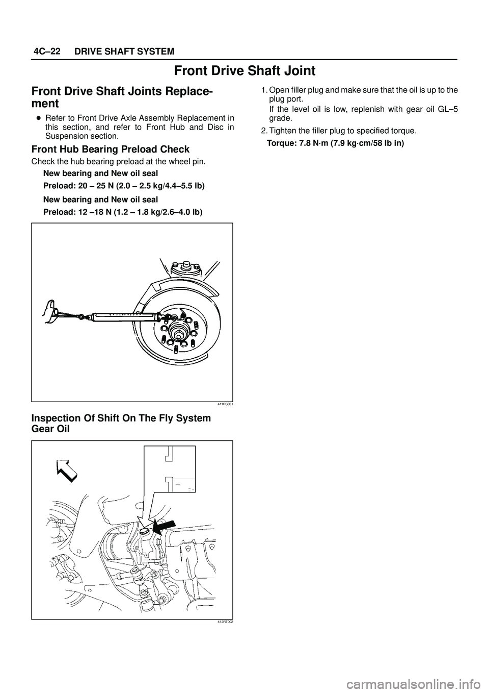
Front Hub Bearing Preload Check
Check the hub bearing preload at the wheel pin.
New bearing and New oil seal
Preload: 20 ± 25 N (2.0 ± 2.5 kg/4.4±5.5 lb)
New bearing and New oil seal
Preload: 12 ±18 N (1.2 ± 1.8 kg/2.6±4.0 lb)
411RS001
Inspection Of Shift On The Fly System
Gear Oil
412RT002
1. Open filler plug and make sure that the oil is up to the
plug port.
If the level oil is low, replenish with gear oil GL±5
grade.
2. Tighten the filler plug to specified torque.
Torque: 7.8 N´m (7.9 kg´cm/58 lb in)
Page 689 of 3573
4C±23 DRIVE SHAFT SYSTEM
Front Axle Drive Shaft
Front Axle Drive Shaft and Associated Parts
This illustration is based on the model equipped with shift on the fly system.
412RW003
Legend
(1) Axle Case and Differential
(2) DOJ Case Assembly
(3) Snap Ring
(4) Bearing
(5) Snap Ring
(6) Oil Seal
(7) Bracket
(8) DOJ Case
(9) Circlip
(10) Bolt
(11) Drive Shaft Joint Assembly
(12) Snap Ring(13) Spacer
(14) Ball
(15) Snap Ring
(16) Ball Retainer
(17) Ball Guide
(18) Band
(19) Bellows
(20) Band
(21) Band
(22) Bellows
(23) Band
(24) BJ Shaft
(25) Dust Seal
Page 694 of 3573
4C±28
DRIVE SHAFT SYSTEM
Shift On The Fly System
Shift On The Fly System and Associated Parts
412RW004
Legend
(1) Filler Plug
(2) Bolt
(3) Oil Seal
(4) Snap Ring(External)
(5) Inner Shaft Bearing
(6) Snap Ring(Internal)
(7) Inner Shaft(8) Needle Bearing
(9) Clutch Gear
(10) Sleeve
(11) Housing
(12) Front Axle Drive Shaft (LH side)with Bracket
(13) Bolt
(14) Actuator Assembly
(15) Bolt
Disassembly
1. Remove filler plug and gasket, drain oil.
2. Loosen mounting bracket fitting bolts and remove
front axle drive shaft from front axle case.3. Remove Actuator Assembly and draw out actuator
ASM.
4. Remove housing.
5. Remove sleeve.
6. Remove clutch gear.