Page 2078 of 3573

6E±185 4JX1±TC ENGINE DRIVEABILITY AND EMISSIONS
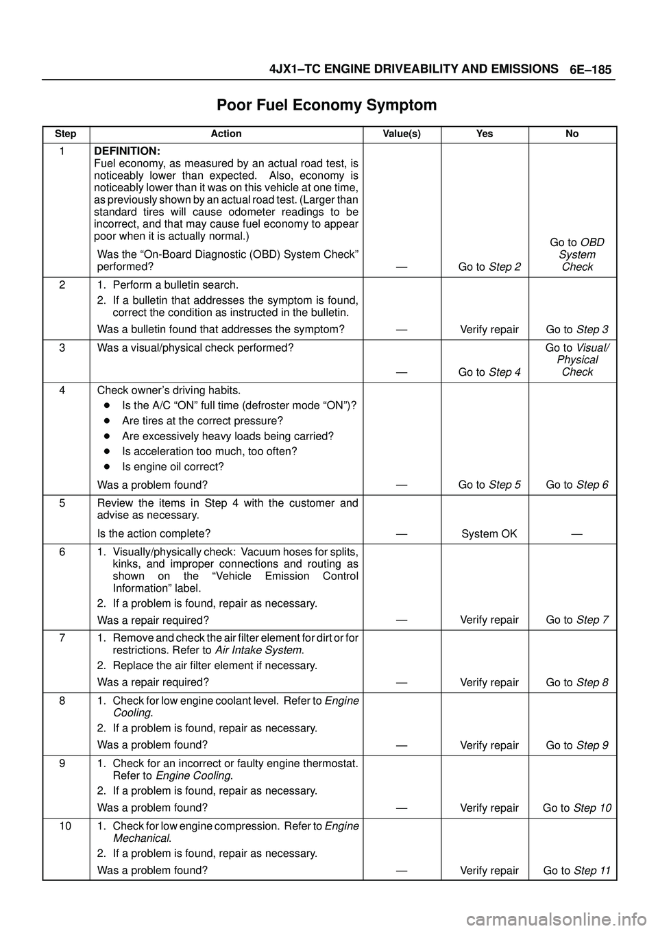
Poor Fuel Economy Symptom�
StepActionValue(s)Ye sNo
1DEFINITION:
Fuel economy, as measured by an actual road test, is
noticeably lower than expected. Also, economy is
noticeably lower than it was on this vehicle at one time,
as previously shown by an actual road test. (Larger than
standard tires will cause odometer readings to be
incorrect, and that may cause fuel economy to appear
poor when it is actually normal.)
Was the ªOn-Board Diagnostic (OBD) System Checkº
performed?
ÐGo to Step 2
Go to OBD
System
Check
21. Perform a bulletin search.
2. If a bulletin that addresses the symptom is found,
correct the condition as instructed in the bulletin.
Was a bulletin found that addresses the symptom?
ÐVerify repairGo to Step 3
3Was a visual/physical check performed?
ÐGo to Step 4
Go to Visual/
Physical
Check
4Check owner's driving habits.
�Is the A/C ªONº full time (defroster mode ªONº)?
�Are tires at the correct pressure?
�Are excessively heavy loads being carried?
�Is acceleration too much, too often?
�Is engine oil correct?
Was a problem found?
ÐGo to Step 5Go to Step 6
5Review the items in Step 4 with the customer and
advise as necessary.
Is the action complete?
ÐSystem OKÐ
61. Visually/physically check: Vacuum hoses for splits,
kinks, and improper connections and routing as
shown on the ªVehicle Emission Control
Informationº label.
2. If a problem is found, repair as necessary.
Was a repair required?
ÐVerify repairGo to Step 7
71. Remove and check the air filter element for dirt or for
restrictions. Refer to
Air Intake System.
2. Replace the air filter element if necessary.
Was a repair required?
ÐVerify repairGo to Step 8
81. Check for low engine coolant level. Refer to Engine
Cooling
.
2. If a problem is found, repair as necessary.
Was a problem found?
ÐVerify repairGo to Step 9
91. Check for an incorrect or faulty engine thermostat.
Refer to
Engine Cooling.
2. If a problem is found, repair as necessary.
Was a problem found?
ÐVerify repairGo to Step 10
101. Check for low engine compression. Refer to Engine
Mechanical
.
2. If a problem is found, repair as necessary.
Was a problem found?
ÐVerify repairGo to Step 11
Page 2297 of 3573

7A1±52
TRANSMISSION CONTROL SYSTEM (4L30±E)
Conditions For Clearing The DTC/CHECK
TRANS Lamp
�The PCM will turn ªoffº the CHECK TRANS Lamp
after three consecutive ignition cycles without a
failure reported.
�The DTC can be cleared from PCM memory by using
a scan tool.
�The DTC can also be cleared from memory when the
vehicle has made 40 warmup cycles without a failure
reported.
�The PCM will cancel the DTC Actions Taken items
when the fault conditions no longer exist and the
ignition is cycles ªoffº long enough to power down the
PCM.
Diagnostic Aids
�Check for intermittent output speed sensor circuit
problems.
�Check for possible incorrect calibration. (PCM part
No., tire specification, and rear axle ratio)
Test Description
The numbers below refer to the step numbers on the
diagnostic chart:
3. This step checks for possible low fluid level causing
slipping resulting in an undefined gear ratio.
4. This step checks for correct gear ratios for
commanded gears.
5. This step checks for low line pressure.
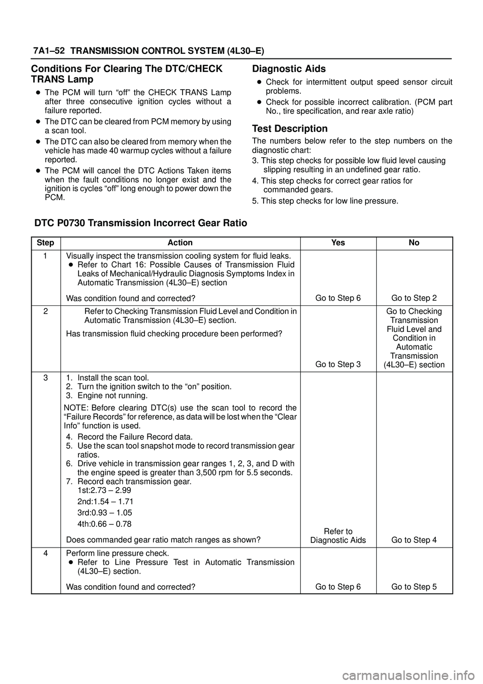
DTC P0730 Transmission Incorrect Gear Ratio
StepActionYe sNo
1Visually inspect the transmission cooling system for fluid leaks.
�Refer to Chart 16: Possible Causes of Transmission Fluid
Leaks of Mechanical/Hydraulic Diagnosis Symptoms Index in
Automatic Transmission (4L30±E) section
Was condition found and corrected?
Go to Step 6Go to Step 2
2Refer to Checking Transmission Fluid Level and Condition in
Automatic Transmission (4L30±E) section.
Has transmission fluid checking procedure been performed?
Go to Step 3
Go to Checking
Transmission
Fluid Level and
Condition in
Automatic
Transmission
(4L30±E) section
31. Install the scan tool.
2. Turn the ignition switch to the ªonº position.
3. Engine not running.
NOTE: Before clearing DTC(s) use the scan tool to record the
ªFailure Recordsº for reference, as data will be lost when the ªClear
Infoº function is used.
4. Record the Failure Record data.
5. Use the scan tool snapshot mode to record transmission gear
ratios.
6. Drive vehicle in transmission gear ranges 1, 2, 3, and D with
the engine speed is greater than 3,500 rpm for 5.5 seconds.
7. Record each transmission gear.
1st:2.73 ± 2.99
2nd:1.54 ± 1.71
3rd:0.93 ± 1.05
4th:0.66 ± 0.78
Does commanded gear ratio match ranges as shown?
Refer to
Diagnostic Aids
Go to Step 4
4Perform line pressure check.
�Refer to Line Pressure Test in Automatic Transmission
(4L30±E) section.
Was condition found and corrected?
Go to Step 6Go to Step 5
Page 2520 of 3573

CLUTCH7C±11
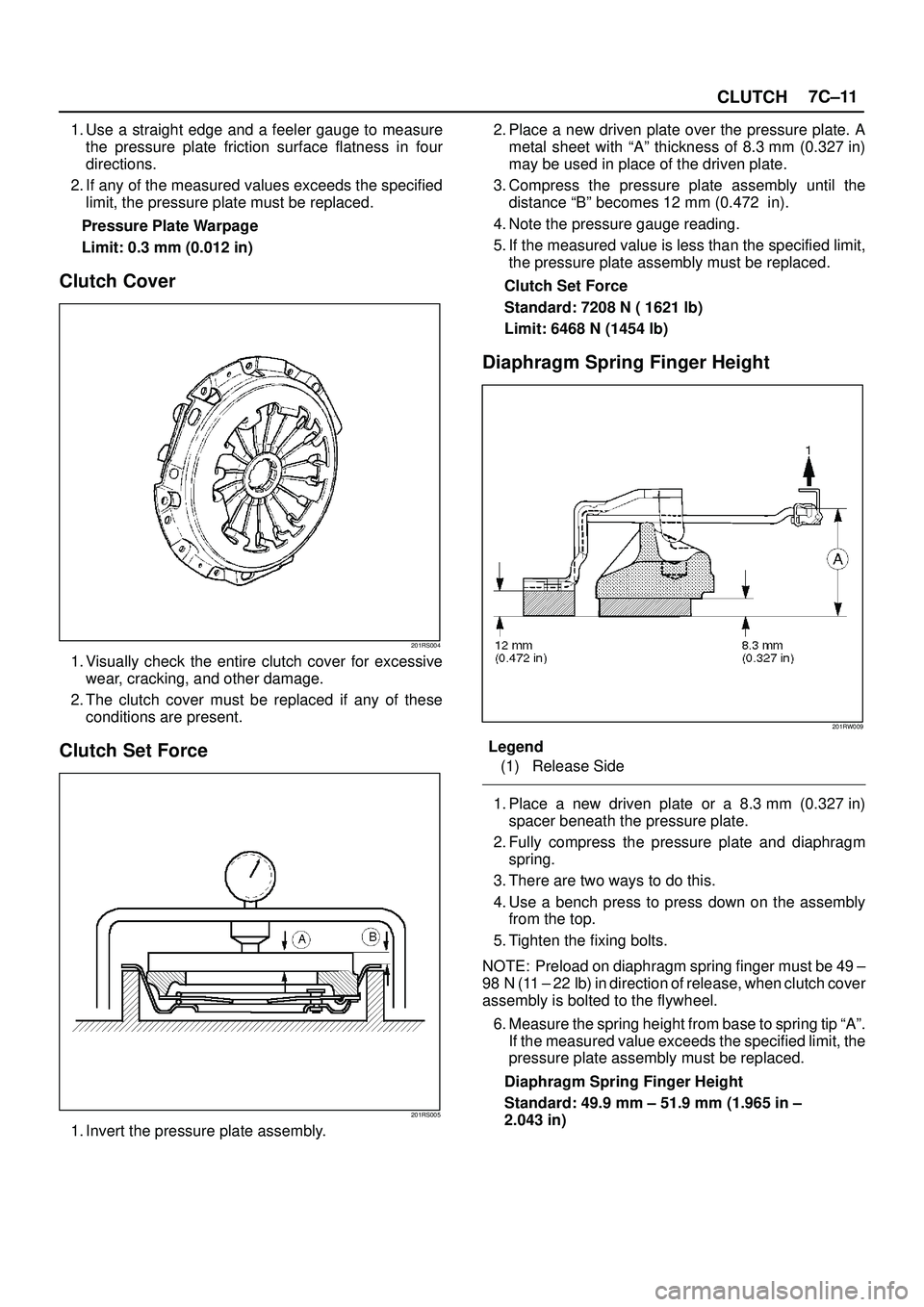
1. Use a straight edge and a feeler gauge to measure
the pressure plate friction surface flatness in four
directions.
2. If any of the measured values exceeds the specified
limit, the pressure plate must be replaced.
Pressure Plate Warpage
Limit: 0.3 mm (0.012 in)
Clutch Cover
201RS004
1. Visually check the entire clutch cover for excessive
wear, cracking, and other damage.
2. The clutch cover must be replaced if any of these
conditions are present.
Clutch Set Force
201RS005
1. Invert the pressure plate assembly.2. Place a new driven plate over the pressure plate. A
metal sheet with ªAº thickness of 8.3 mm (0.327 in)
may be used in place of the driven plate.
3. Compress the pressure plate assembly until the
distance ªBº becomes 12 mm (0.472 in).
4. Note the pressure gauge reading.
5. If the measured value is less than the specified limit,
the pressure plate assembly must be replaced.
Clutch Set Force
Standard: 7208 N ( 1621 lb)
Limit: 6468 N (1454 lb)
Diaphragm Spring Finger Height
201RW009
Legend
(1) Release Side
1. Place a new driven plate or a 8.3 mm (0.327 in)
spacer beneath the pressure plate.
2. Fully compress the pressure plate and diaphragm
spring.
3. There are two ways to do this.
4. Use a bench press to press down on the assembly
from the top.
5. Tighten the fixing bolts.
NOTE: Preload on diaphragm spring finger must be 49 ±
98 N (11 ± 22 lb) in direction of release, when clutch cover
assembly is bolted to the flywheel.
6. Measure the spring height from base to spring tip ªAº.
If the measured value exceeds the specified limit, the
pressure plate assembly must be replaced.
Diaphragm Spring Finger Height
Standard: 49.9 mm ± 51.9 mm (1.965 in ±
2.043 in)
Page 2543 of 3573

8A–4LIGHTING SYSTEM
Headlight
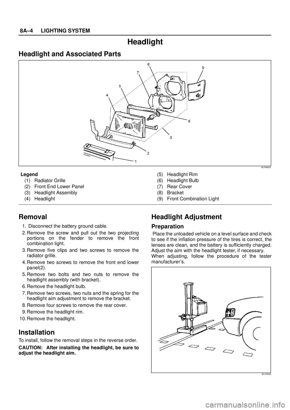
Headlight and Associated Parts
801RW003
Legend
(1) Radiator Grille
(2) Front End Lower Panel
(3) Headlight Assembly
(4) Headlight(5) Headlight Rim
(6) Headlight Bulb
(7) Rear Cover
(8) Bracket
(9) Front Combination Light
Removal
1. Disconnect the battery ground cable.
2. Remove the screw and pull out the two projecting
portions on the fender to remove the front
combination light.
3. Remove five clips and two screws to remove the
radiator grille.
4. Remove two screws to remove the front end lower
panel(2).
5. Remove two bolts and two nuts to remove the
headlight assembly (with bracket).
6. Remove the headlight bulb.
7. Remove two screws, two nuts and the spring for the
headlight aim adjustment to remove the bracket.
8. Remove four screws to remove the rear cover.
9. Remove the headlight rim.
10. Remove the headlight.
Installation
To install, follow the removal steps in the reverse order.
CAUTION: After installing the headlight, be sure to
adjust the headlight aim.
Headlight Adjustment
Preparation
Place the unloaded vehicle on a level surface and check
to see if the inflation pressure of the tires is correct, the
lenses are clean, and the battery is sufficiently charged.
Adjust the aim with the headlight tester, if necessary.
When adjusting, follow the procedure of the tester
manufacturer’s.
801RS009