Page 997 of 3573
6A±41
ENGINE MECHANICAL
3. Remove oil strainer fixing bolts, remove oil strainer
assembly with O-ring.
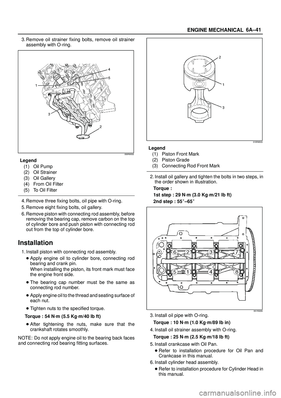
050RW002
Legend
(1) Oil Pump
(2) Oil Strainer
(3) Oil Gallery
(4) From Oil Filter
(5) To Oil Filter
4. Remove three fixing bolts, oil pipe with O-ring.
5. Remove eight fixing bolts, oil gallery.
6. Remove piston with connecting rod assembly, before
removing the bearing cap, remove carbon on the top
of cylinder bore and push piston with connecting rod
out from the top of cylinder bore.
Installation
1. Install piston with connecting rod assembly.
�Apply engine oil to cylinder bore, connecting rod
bearing and crank pin.
When installing the piston, its front mark must face
the engine front side.
�The bearing cap number must be the same as
connecting rod number.
�Apply engine oil to the thread and seating surface of
each nut.
�Tighten nuts to the specified torque.
Torque : 54 N´m (5.5 Kg´m/40 lb ft)
�After tightening the nuts, make sure that the
crankshaft rotates smoothly.
NOTE: Do not apply engine oil to the bearing back faces
and connecting rod bearing fitting surfaces.
015RW003
Legend
(1) Piston Front Mark
(2) Piston Grade
(3) Connecting Rod Front Mark
2. Install oil gallery and tighten the bolts in two steps, in
the order shown in illustration.
Torque :
1st step : 29 N´m (3.0 Kg´m/21 lb ft)
2nd step : 55�±65�
051RS009
3. Install oil pipe with O-ring.
Torque : 10 N´m (1.0 Kg´m/89 lb in)
4. Install oil strainer assembly with O-ring.
Torque : 25 N´m (2.5 Kg´m/18 lb ft)
5. Install crankcase with Oil Pan.
�Refer to installation procedure for Oil Pan and
Crankcase in this manual.
6. Install cylinder head assembly.
�Refer to installation procedure for Cylinder Head in
this manual.
Page 998 of 3573
6A±42
ENGINE MECHANICAL
Crankshaft and Main Bearings
Removal
F06RW010
Legend
(1) Engine Assembly
(2) Crankshaft Pulley
(3) Timing Belt Cover
(4) Timing Belt
(5) Crankcase with Oil Pan
(6) Oil Pipe
(7) Oil Strainer(8) Oil Pump Assembly
(9) Cylinder Body Side Bolt
(10) Oil Gallery
(11) Flywheel
(12) Rear Oil Seal Retainer
(13) Connecting Rod Cap
(14) Crankshaft Main Bearing Cap
(15) Crankshaft and Main Bearing
1. Remove engine assembly.
�Refer to removal procedure for Engine Assembly in
this manual.
2. Remove timing belt.
�Refer to removal procedure for Timing Belt in this
manual.3. Remove oil pan and crankcase.
�Refer to removal procedure for Oil Pan and
Crankcase in this manual.
4. Remove oil pipe with O-ring.
5. Remove oil strainer assembly with O-ring.
Page 999 of 3573

6A±43
ENGINE MECHANICAL
6. Remove oil pump assembly.
�Refer to removal procedure for Oil Pump in this
manual.
7. Remove cylinder body side bolts.
8. Remove oil gallery.
9. Remove flywheel.
10. Remove rear oil seal retainer.
�Refer to removal procedure for Rear Oil Seal in this
manual.
11. Remove connecting rod caps.
12. Remove crankshaft main bearing caps.
13. Remove crankshaft and main bearings.
Installation
1. Install crankshaft and main bearings.
�Install main bearing in the cylinder block and main
bearing cap respectively.
Apply new engine oil to upper and lower main
bearings.
NOTE:
�Do not apply engine oil to the bearing back faces.
�Make sure that main bearings are in correct position.
�Install crankshaft with care.
�Apply engine oil to the thrust washer.
�Install thrust washer on No.3 journal.
�Oil grooves in thrust washer must face the
crankshaft.
015RS012
015RS013
2. Install crankshaft main bearing caps.
�Apply engine oil to the thread and seating surface of
each bearing cap fixing bolt.
NOTE:
�Do not apply engine oil to the bearing back faces.
�Install bearing caps in the order of numbers, starting
with cylinder block front side.
�Tighten main bearing fixing bolts to the specified
torque.
Torque : 39 N´m (4.0 Kg´m/29 lb ft)
�After tightening the bolts, make sure that the
crankshaft rotates smoothly.
3. Install connecting rod caps.
�The cap number must be same as connecting rod
number.
�Apply engine oil to the thread and seating surface of
each nut.
�Tighten nuts to the specified torque.
Torque : 54 N´m (5.5 Kg´m/40 lb ft)
�After tightening the nuts, make sure that the
crankshaft rotates smoothly.
4. Install rear oil seal retainer.
�Remove oil on cylinder block and retainer fitting
surface.
�Apply sealant (TB1207B or equivalent) to retainer
fitting surface as shown in illustration.
Page 1000 of 3573

6A±44
ENGINE MECHANICAL
�The oil seal retainer must be installed within 5
minutes after sealant application before the sealant
hardens.
015RW002
Legend
(1) Around Bolt Holes
(2) Around Dowel Pin
�Apply engine oil to oil seal lip and align a dowel pin
hole in the cylinder block with that in the retainer.
�Tighten retainer fixing bolts to the specified torque.
Torque : 18 N´m (1.8 Kg´m/13 lb ft)
015RW001
5. Install flywheel.
�Clean tapped holes in the crankshaft.
�Remove oil on crankshaft and flywheel fitting
surface.
NOTE:
�Do not reuse the bolts.
�Do not apply oil or thread lock to the bolts.�Tighten fixing bolts to the specified torque.
Torque : 54 N´m (5.5 Kg´m/40 lb ft)
015RS018
6. Install oil gallery.
�Clean contact surface of oil gallery and main
bearing cap.
Apply engine oil to oil gallery fixing bolts and tighten
the bolts in two steps, in the order shown in
illustration.
Torque :
1st step : 29 N´m (3.0 Kg´m/21 lb ft)
2nd step : 55�±65�
7. Install cylinder body side bolts and tighten bolts in
order to the specified torque.
Torque : 39 N´m (4.0 Kg´m/29 lb ft)
NOTE: Do not apply the oil to the bolts.
012RS007
8. Install oil pump assembly.
�Remove oil on cylinder block and oil pump mounting
surface.
Page 1003 of 3573

6A±47
ENGINE MECHANICAL
Rear Oil Seal
Removal
1. Remove transmission assembly.
�Refer to removal procedure for Transmission
section in this manual.
2. Remove flywheel.
3. Remove rear oil seal using a seal remover.
NOTE: Take care not to damage the crankshaft or oil seal
retainer when removing oil seal.
Installation
1. Apply engine oil to oil seal lip and install oil seal using
5±8840±2286±0.
015RS017
2. Install flywheel.
�Clean tapped holes in the crankshaft.
�Remove oil on the crankshaft and flywheel
mounting surface.
�Tighten fixing bolts to the specified torque.
NOTE: Do not reuse the bolts and do not apply oil or
thread lock to the bolts.
Torque : 54 N´m (5.5 Kg´m/40 lb ft)
015RS018
3. Install transmission.
�See Transmission section in this manual.
CAUTION: W h e n assembling the engine and
transmission, confirm that dowels have been
mounted in the specified positions at the engine
side. Take care that dowel positions are different
between the manual transmission and the automatic
transmission.
Otherwise, the transmission may be damaged.
012RS009
Page 1006 of 3573
6A±50
ENGINE MECHANICAL
9. Install air conditioner compressor to engine and
tighten to the specified torque.
Torque :
M8 bolts : 22 N´m (2.2 Kg´m/16 lb ft)
M10 bolts : 43 N´m (4.4 Kg´m/32 lb ft)
10. Install power steering pump, tighten fixing bolt to the
specified torque.
Torque :
M8 bolts : 22N´m (2.2 Kg´m/16 lb ft)
M10 bolts : 46 N´m (4.7 Kg´m/34 lb ft)
11. Move drive belt tensioner to loose side using wrench,
then install drive belt to normal position.
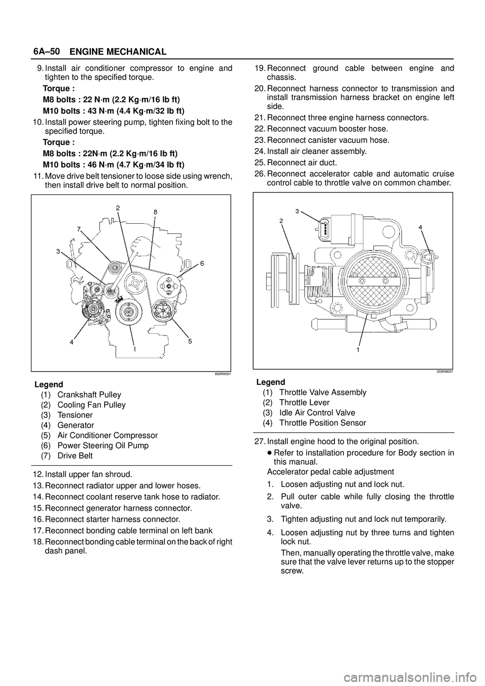
850RW001
Legend
(1) Crankshaft Pulley
(2) Cooling Fan Pulley
(3) Tensioner
(4) Generator
(5) Air Conditioner Compressor
(6) Power Steering Oil Pump
(7) Drive Belt
12. Install upper fan shroud.
13. Reconnect radiator upper and lower hoses.
14. Reconnect coolant reserve tank hose to radiator.
15. Reconnect generator harness connector.
16. Reconnect starter harness connector.
17. Reconnect bonding cable terminal on left bank
18. Reconnect bonding cable terminal on the back of right
dash panel.19. Reconnect ground cable between engine and
chassis.
20. Reconnect harness connector to transmission and
install transmission harness bracket on engine left
side.
21. Reconnect three engine harness connectors.
22. Reconnect vacuum booster hose.
23. Reconnect canister vacuum hose.
24. Install air cleaner assembly.
25. Reconnect air duct.
26. Reconnect accelerator cable and automatic cruise
control cable to throttle valve on common chamber.
035RW007
Legend
(1) Throttle Valve Assembly
(2) Throttle Lever
(3) Idle Air Control Valve
(4) Throttle Position Sensor
27. Install engine hood to the original position.
�Refer to installation procedure for Body section in
this manual.
Accelerator pedal cable adjustment
1. Loosen adjusting nut and lock nut.
2. Pull outer cable while fully closing the throttle
valve.
3. Tighten adjusting nut and lock nut temporarily.
4. Loosen adjusting nut by three turns and tighten
lock nut.
Then, manually operating the throttle valve, make
sure that the valve lever returns up to the stopper
screw.
Page 1025 of 3573
6A±69
ENGINE MECHANICAL
Crankshaft
Crankshaft and Associated Parts
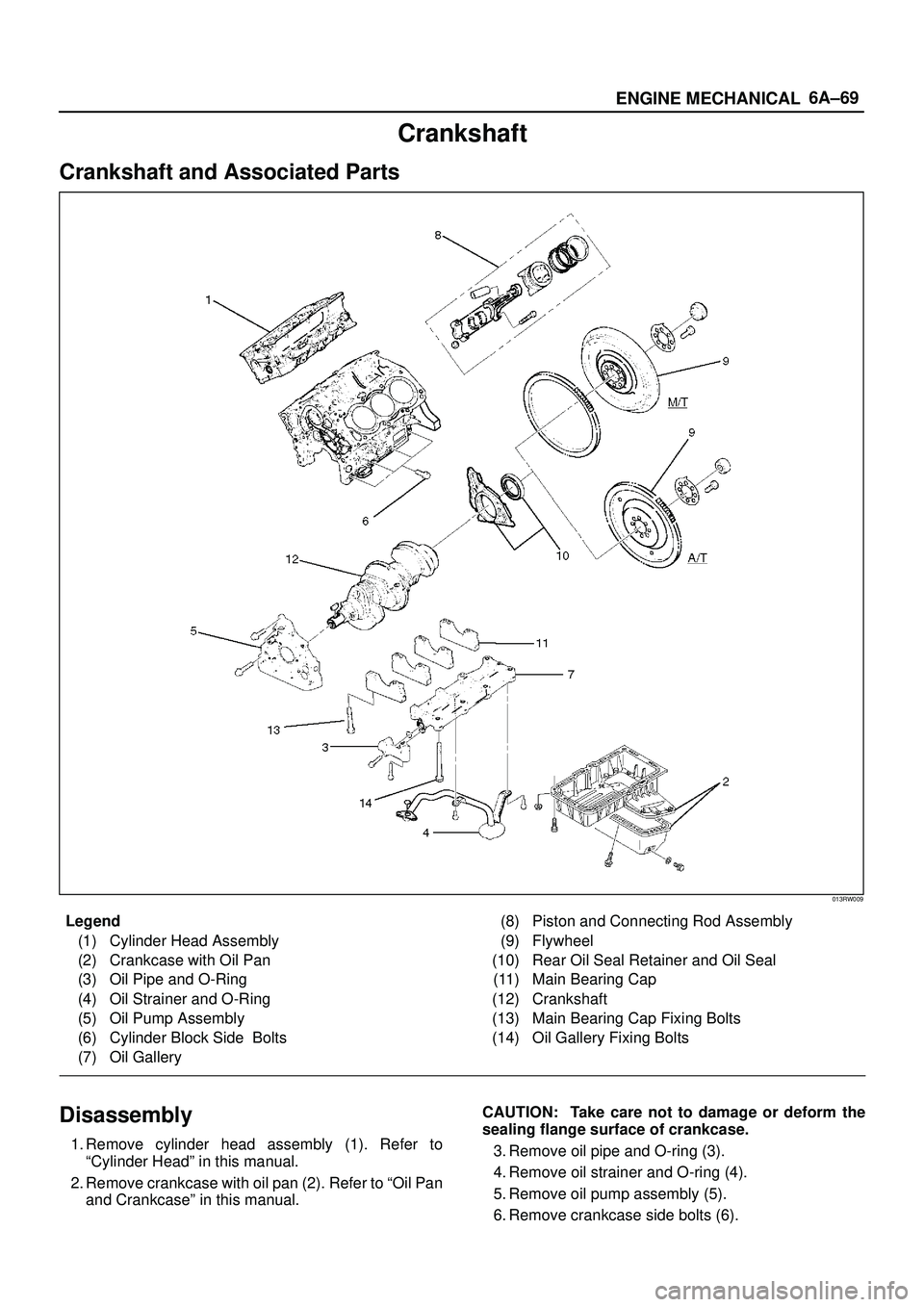
013RW009
Legend
(1) Cylinder Head Assembly
(2) Crankcase with Oil Pan
(3) Oil Pipe and O-Ring
(4) Oil Strainer and O-Ring
(5) Oil Pump Assembly
(6) Cylinder Block Side Bolts
(7) Oil Gallery(8) Piston and Connecting Rod Assembly
(9) Flywheel
(10) Rear Oil Seal Retainer and Oil Seal
(11) Main Bearing Cap
(12) Crankshaft
(13) Main Bearing Cap Fixing Bolts
(14) Oil Gallery Fixing Bolts
Disassembly
1. Remove cylinder head assembly (1). Refer to
ªCylinder Headº in this manual.
2. Remove crankcase with oil pan (2). Refer to ªOil Pan
and Crankcaseº in this manual.CAUTION: Take care not to damage or deform the
sealing flange surface of crankcase.
3. Remove oil pipe and O-ring (3).
4. Remove oil strainer and O-ring (4).
5. Remove oil pump assembly (5).
6. Remove crankcase side bolts (6).
Page 1026 of 3573
6A±70
ENGINE MECHANICAL
7. Remove oil gallery (7).
8. Remove piston and connecting rod assembly (8).
Refer to ªPiston, Piston Ring and Connecting Rodº in
this manual.
9. Remove flywheel (9).
10. Remove rear oil seal retainer (10).
11. Remove main bearing cap (11).
12. Remove crankshaft (12).
Inspection and Repair
1. Crankshaft
Set the dial indicator as shown in the illustration and
measure the crankshaft thrust clearance. If the thrust
clearance exceeds the specified limit, replace the
thrust bearings as a set.
Thrust Clearance
Standard : 0.06 mm±0.24 mm
(0.0024 in±0.0094 in)
Limit : 0.30 mm (0.0118 in)
015RS003
Main Bearing Clearance
1. Remove the bearing caps and measure the oil
clearance.
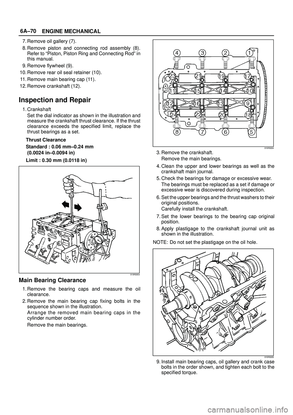
2. Remove the main bearing cap fixing bolts in the
sequence shown in the illustration.
Arrange the removed main bearing caps in the
cylinder number order.
Remove the main bearings.
015RS004
3. Remove the crankshaft.
Remove the main bearings.
4. Clean the upper and lower bearings as well as the
crankshaft main journal.
5. Check the bearings for damage or excessive wear.
The bearings must be replaced as a set if damage or
excessive wear is discovered during inspection.
6. Set the upper bearings and the thrust washers to their
original positions.
Carefully install the crankshaft.
7. Set the lower bearings to the bearing cap original
position.
8. Apply plastigage to the crankshaft journal unit as
shown in the illustration.
NOTE: Do not set the plastigage on the oil hole.
015RS005
9. Install main bearing caps, oil gallery and crank case
bolts in the order shown, and tighten each bolt to the
specified torque.