Page 2557 of 3573

8A–18LIGHTING SYSTEM
Lighting Switch (Combination Switch)
Removal
1. Disconnect the battery ground cable.
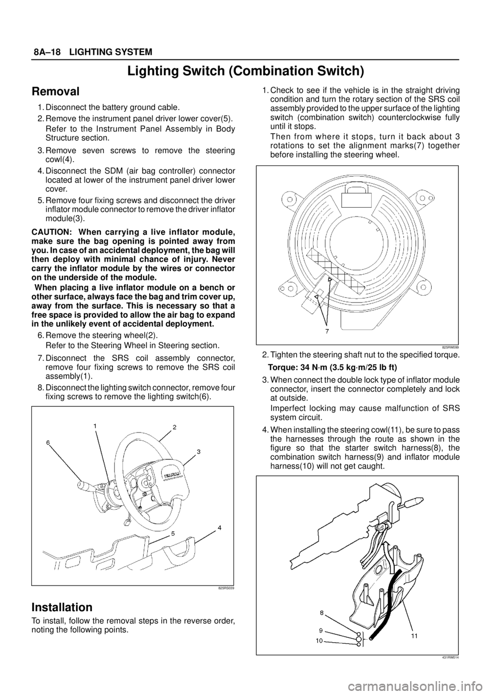
2. Remove the instrument panel driver lower cover(5).
Refer to the Instrument Panel Assembly in Body
Structure section.
3. Remove seven screws to remove the steering
cowl(4).
4. Disconnect the SDM (air bag controller) connector
located at lower of the instrument panel driver lower
cover.
5. Remove four fixing screws and disconnect the driver
inflator module connector to remove the driver inflator
module(3).
CAUTION: When carrying a live inflator module,
make sure the bag opening is pointed away from
you. In case of an accidental deployment, the bag will
then deploy with minimal chance of injury. Never
carry the inflator module by the wires or connector
on the underside of the module.
When placing a live inflator module on a bench or
other surface, always face the bag and trim cover up,
away from the surface. This is necessary so that a
free space is provided to allow the air bag to expand
in the unlikely event of accidental deployment.
6. Remove the steering wheel(2).
Refer to the Steering Wheel in Steering section.
7. Disconnect the SRS coil assembly connector,
remove four fixing screws to remove the SRS coil
assembly(1).
8. Disconnect the lighting switch connector, remove four
fixing screws to remove the lighting switch(6).
825RS039
Installation
To install, follow the removal steps in the reverse order,
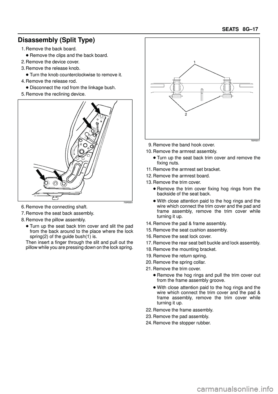
noting the following points.1. Check to see if the vehicle is in the straight driving
condition and turn the rotary section of the SRS coil
assembly provided to the upper surface of the lighting
switch (combination switch) counterclockwise fully
until it stops.
Then from where it stops, turn it back about 3
rotations to set the alignment marks(7) together
before installing the steering wheel.
825RW099
2. Tighten the steering shaft nut to the specified torque.
Torque: 34 N·m (3.5 kg·m/25 lb ft)
3. When connect the double lock type of inflator module
connector, insert the connector completely and lock
at outside.
Imperfect locking may cause malfunction of SRS
system circuit.
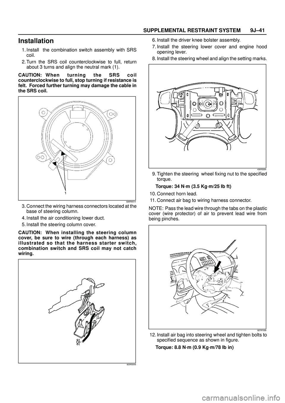
4. When installing the steering cowl(11), be sure to pass
the harnesses through the route as shown in the
figure so that the starter switch harness(8), the
combination switch harness(9) and inflator module
harness(10) will not get caught.
431RW014
Page 3329 of 3573

SEATS8G±17
Disassembly (Split Type)
1. Remove the back board.
�Remove the clips and the back board.
2. Remove the device cover.
3. Remove the release knob.
�Turn the knob counterclockwise to remove it.
4. Remove the release rod.
�Disconnect the rod from the linkage bush.
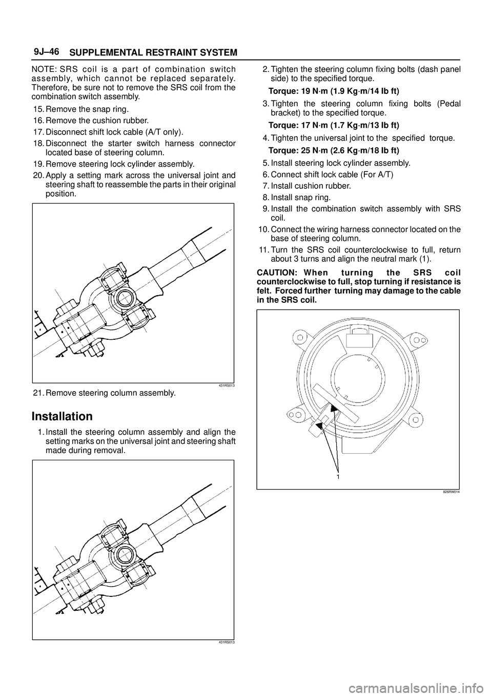
5. Remove the reclining device.
755RS004
6. Remove the connecting shaft.
7. Remove the seat back assembly.
8. Remove the pillow assembly.
�Turn up the seat back trim cover and slit the pad
from the back around to the place where the lock
spring(2) of the guide bush(1) is.
Then insert a finger through the slit and pull out the
pillow while you are pressing down on the lock spring.
755RS017
9. Remove the band hook cover.
10. Remove the armrest assembly.
�Turn up the seat back trim cover and remove the
fixing nuts.
11. Remove the armrest set bracket.
12. Remove the armrest board.
13. Remove the trim cover.
�Remove the trim cover fixing hog rings from the
backside of the seat back.
�With close attention paid to the hog rings and the
wire which connect the trim cover and the pad and
frame assembly, remove the trim cover while
turning it up.
14. Remove the pad & frame assembly.
15. Remove the seat cushion assembly.
16. Remove the seat lock cover.
17. Remove the rear seat belt buckle and lock assembly.
18. Remove the mounting bracket.
19. Remove the return spring.
20. Remove the spring collar.
21. Remove the trim cover.
�Remove the hog rings and pull the trim cover out
from the frame assembly groove.
�With close attention paid to the hog rings and the
wire which connect the trim cover and the pad &
frame assembly, remove the trim cover while
turning it up.
22. Remove the frame assembly.
23. Remove the pad assembly.
24. Remove the stopper rubber.
Page 3331 of 3573
SEATS8G±19
Disassembled View (Short Wheel Base)
755RW036
Legend
(1) Back Board
(2) Release Knob
(3) Release Rod
(4) Device Cover
(5) Reclining Device
(6) Linkage Bush
(7) Pillow Assembly
(8) Pad & Frame Assembly
(9) Armrest Board
(10) Clip
(11) Band Hook Cover
(12) Trim Cover(13) Armrest Set Bracket
(14) Bush
(15) Armrest Assembly
(16) Trim Cover
(17) Mounting Bracket
(18) Frame Assembly
(19) Stopper Rubber
(20) Pad Assembly
(21) Seat Lock Cover
(22) Rear seat Belt Bukle and Lock Assembly
(23) Seat Cushion Assembly
(24) Free Hinge Cover
(25) Seat Back Assembly
Disassembly
1. Remove the back board.
�Remove the clips and the back board.2. Remove the device cover.
3. Remove the release knob.
�Turn the knob counterclockwise to remove it.
Page 3478 of 3573

SUPPLEMENTAL RESTRAINT SYSTEM9J±41
Installation
1. Install the combination switch assembly with SRS
coil.
2. Turn the SRS coil counterclockwise to full, return
about 3 turns and align the neutral mark (1).
CAUTION: W h e n t u r n i n g t h e S R S c o i l
counterclockwise to full, stop turning if resistance is
felt. Forced further turning may damage the cable in
the SRS coil.
826RW014
3. Connect the wiring harness connectors located at the
base of steering column.
4. Install the air conditioning lower duct.
5. Install the steering column cover.
CAUTION: When installing the steering column
cover, be sure to wire (through each harness) as
illustrated so that the harness starter switch,
combination switch and SRS coil may not catch
wiring.
825RS048
6. Install the driver knee bolster assembly.
7. Install the steering lower cover and engine hood
opening lever.
8. Install the steering wheel and align the setting marks.
430RS004
9. Tighten the steering wheel fixing nut to the specified
torque.
Torque: 34 N´m (3.5 Kg´m/25 Ib ft)
10. Connect horn lead.
11. Connect air bag to wiring harness connector.
NOTE: Pass the lead wire through the tabs on the plastic
cover (wire protector) of air to prevent lead wire from
being pinches.
827RT009
12. Install air bag into steering wheel and tighten bolts to
specified sequence as shown in figure.
Torque: 8.8 N´m (0.9 Kg´m/78 Ib in)
Page 3483 of 3573

SUPPLEMENTAL RESTRAINT SYSTEM 9J±46
NOTE: S R S c o i l i s a p a r t o f combination switch
assembly, which cannot be replaced separately.
Therefore, be sure not to remove the SRS coil from the
combination switch assembly.
15. Remove the snap ring.
16. Remove the cushion rubber.
17. Disconnect shift lock cable (A/T only).
18. Disconnect the starter switch harness connector
located base of steering column.
19. Remove steering lock cylinder assembly.
20. Apply a setting mark across the universal joint and
steering shaft to reassemble the parts in their original
position.
431RS013
21. Remove steering column assembly.
Installation
1. Install the steering column assembly and align the
setting marks on the universal joint and steering shaft
made during removal.
431RS013
2. Tighten the steering column fixing bolts (dash panel
side) to the specified torque.
Torque: 19 N´m (1.9 Kg´m/14 Ib ft)
3. Tighten the steering column fixing bolts (Pedal
bracket) to the specified torque.
Torque: 17 N´m (1.7 Kg´m/13 Ib ft)
4. Tighten the universal joint to the specified torque.
Torque: 25 N´m (2.6 Kg´m/18 Ib ft)
5. Install steering lock cylinder assembly.
6. Connect shift lock cable (For A/T)
7. Install cushion rubber.
8. Install snap ring.
9. Install the combination switch assembly with SRS
coil.
10. Connect the wiring harness connector located on the
base of steering column.
11. Turn the SRS coil counterclockwise to full, return
about 3 turns and align the neutral mark (1).
CAUTION: W h e n t u r n i n g t h e S R S c o i l
counterclockwise to full, stop turning if resistance is
felt. Forced further turning may damage to the cable
in the SRS coil.
826RW014
Page:
< prev 1-8 9-16 17-24