Page 481 of 3573
4A2A±14
DIFFERENTIAL (REAR 220mm)
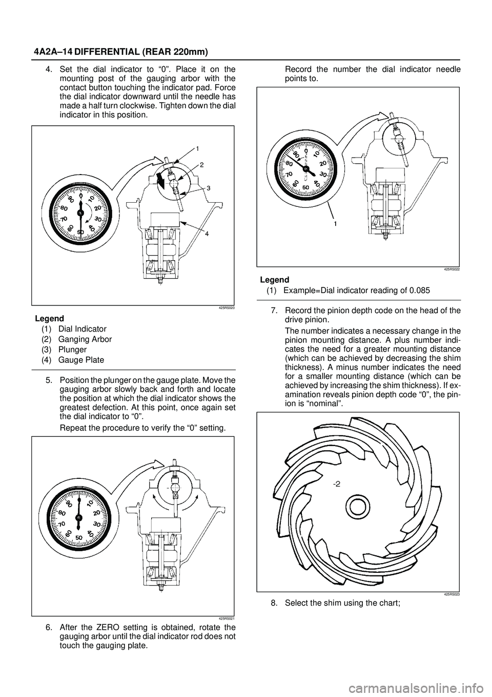
4. Set the dial indicator to ª0º. Place it on the
mounting post of the gauging arbor with the
contact button touching the indicator pad. Force
the dial indicator downward until the needle has
made a half turn clockwise. Tighten down the dial
indicator in this position.
425RS020
Legend
(1) Dial Indicator
(2) Ganging Arbor
(3) Plunger
(4) Gauge Plate
5. Position the plunger on the gauge plate. Move the
gauging arbor slowly back and forth and locate
the position at which the dial indicator shows the
greatest defection. At this point, once again set
the dial indicator to ª0º.
Repeat the procedure to verify the ª0º setting.
425RS021
6. After the ZERO setting is obtained, rotate the
gauging arbor until the dial indicator rod does not
touch the gauging plate.Record the number the dial indicator needle
points to.
425RS022
Legend
(1) Example=Dial indicator reading of 0.085
7. Record the pinion depth code on the head of the
drive pinion.
The number indicates a necessary change in the
pinion mounting distance. A plus number indi-
cates the need for a greater mounting distance
(which can be achieved by decreasing the shim
thickness). A minus number indicates the need
for a smaller mounting distance (which can be
achieved by increasing the shim thickness). If ex-
amination reveals pinion depth code ª0º, the pin-
ion is ªnominalº.
425RS023
8. Select the shim using the chart;
Page 517 of 3573
4A2B±14DIFFERENTIAL (REAR 244mm)
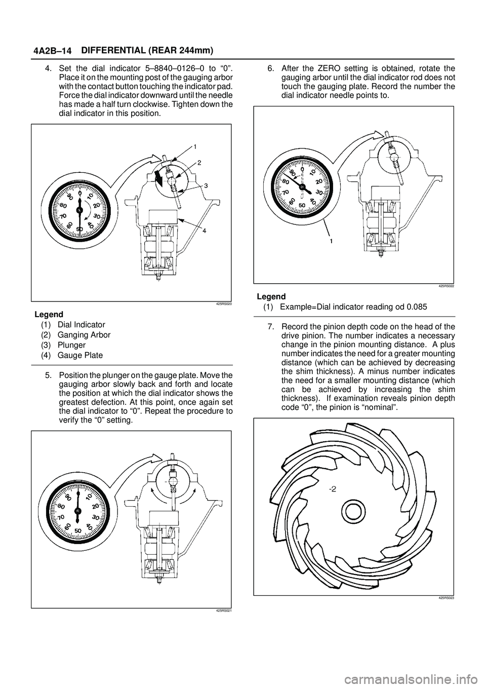
4. Set the dial indicator 5±8840±0126±0 to ª0º.
Place it on the mounting post of the gauging arbor
with the contact button touching the indicator pad.
Force the dial indicator downward until the needle
has made a half turn clockwise. Tighten down the
dial indicator in this position.
425RS020
Legend
(1) Dial Indicator
(2) Ganging Arbor
(3) Plunger
(4) Gauge Plate
5. Position the plunger on the gauge plate. Move the
gauging arbor slowly back and forth and locate
the position at which the dial indicator shows the
greatest defection. At this point, once again set
the dial indicator to ª0º. Repeat the procedure to
verify the ª0º setting.
425RS021
6. After the ZERO setting is obtained, rotate the
gauging arbor until the dial indicator rod does not
touch the gauging plate. Record the number the
dial indicator needle points to.
425RS022
Legend
(1) Example=Dial indicator reading od 0.085
7. Record the pinion depth code on the head of the
drive pinion. The number indicates a necessary
change in the pinion mounting distance. A plus
number indicates the need for a greater mounting
distance (which can be achieved by decreasing
the shim thickness). A minus number indicates
the need for a smaller mounting distance (which
can be achieved by increasing the shim
thickness). If examination reveals pinion depth
code ª0º, the pinion is ªnominalº.
425RS023
Page 681 of 3573

4C±15 DRIVE SHAFT SYSTEM
3. Remove bolt.
Before removal, shift transfer lever into ª2Hº position,
set free wheeling hub knob into ªFREEº position (1),
and run the vehicle about 50m (160 ft).
411RW010
4. Remove cover assembly.
5. Remove snap ring and shim.
6. Remove body assembly.
7. Remove lock washer and lock screw.
8. Remove hub nut by using wrench 5±8840±2117±0.
411RW005
9. Remove hub and disc assembly.
10. Remove ABS sensor ring (If equipped).
11. Remove outer bearing outer race.
12. Remove oil seal.13. Remove inner bearing outer race.
14. While pushing follower knob against cover, turn clutch
assembly clockwise and then remove clutch
assembly from knob.
411RW011
15. Remove gasket.
16. Remove snap ring.
17. Remove knob.
18. Remove compression spring.
19. Remove follower.
20. Remove retaining spring from clutch assembly by
turning it counterclockwise.
411RW012
21. Remove dedent ball and spring.
22. Remove X±ring.
23. Remove snap ring.
24. Remove inner assembly.
25. Remove snap ring.
26. Remove ring.
27. Remove spacer.
Page 987 of 3573

6A±31
ENGINE MECHANICAL
2. Align the alignment mark on the RH bank
camshaft drive gear pulley (2) to the alignment
mark of the cylinder head cover RH (3).
3. Align the alignment mark (white line) on the timing
belt (1) with alignment mark on the RH bank
camshaft drive gear pulley (2) (on the left side as
viewed from the front of the vehicle) and put the
timing belt on the camshaft drive gear pulley.
Secure the belt with a double clip or equivalent
clip.
014RW00004
Legend
(1) Alignment Mark on Timing Belt (White line).
(2) Alignment Mark on Camshaft Drive Gear
Pulley.
(3) Alignemnt Mark on Cylinder Head Cover RH.
4. Align the alignment mark on the LH bank
camshaft drive gear pulley (2) to the alignment
mark of the cylinder head cover LH (3).
5. Align the alignment mark (white line) on the timing
belt (1) with the alignment mark on the LH bank
camshaft drive gear pulley (2).
When aligning the timing marks, use a wrench to
turn the camshaft drive gear pulley, then set the
timing mark between timing belt and camshaft
drive gear pulley and put the timing belt on the
camshaft drive gear pulley.
Secure the belt with a double clip or equivalent
clip.
NOTE: It is recommended for easy installation that the
belt be secured with a double clip or equivalent clip after
it is installed the timing belt to each pulley.
014RW00005
Legend
(1) Alignment Mark on Timing Belt (White line).
(2) Alignment Mark on Camshaft Drive Gear
Pulley.
(3) Alignemnt Mark on Cylinder Head Cover LH.
6. Install crankshaft pulley temporarily and tighten
center bolt by hand (do not use a wrench).
Turn the crankshaft pulley clockwise to give some
belt slack between the crankshaft timing pulley
and the RH bank camshaft drive gear pulley.
2. Install pusher and tighten bolt to the specified torque.
Torque : 25 N´m (2.5 Kg´m/18 lb ft)
1. Install the pusher while pushing the tension pulley
to the belt.
2. Pull out pin from the pusher.
NOTE: When reusing the pusher, press the pusher with
approximately 100Kg to retract the rod, and insert a pin
(1.4 mm piano wire).
014RW011
Page 1375 of 3573
6E±258
ENGINE DRIVEABILITY AND EMISSIONS
Diagnostic Trouble Code (DTC) P1625 PCM Unexpected Reset
Circuit Description
The powertrain control module (PCM) monitors
unexpected PCM reset. This will not turn on MIL light on,
only records code DTC P1625.
Conditions for Setting the DTC
�Clock or COP reset.
Action Taken When the DTC Sets
�The PCM will not illuminate the malfunction indicator
lamp (MIL).
�The PCM will store conditions which were present
when the DTC was set as Failure Records only. This
information will not be stored as Freeze Frame data.
Conditions for Clearing the MIL/DTC
�DTC P1625 can be cleared by using the Tech 2 ªClear
Infoº function or by disconnecting the PCM battery
feed.
Diagnostic Aids
Check for the following conditions:
�P1625 alone stored does not need diagnosis. Clear
DTC code.
Page 1594 of 3573
6A Ð 44 ENGINE MECHANICAL
INSPECTION REPAIR
Make the necessary adjustments, repairs, and part replacements if excessive wear or damage is discovered
during inspection.
1. Remove the gasket and any other material adhering to
the upper surface of the cylinder block.
Be very careful not to allow any material to accidentally
drop into the cylinder block.
Be very careful not to scratch the cylinder block.
2. Carefully remove the oil pump, Rear Oil Seal retainer,
and oil pan installation surface seal.
3. Wipe the cylinder block clean.
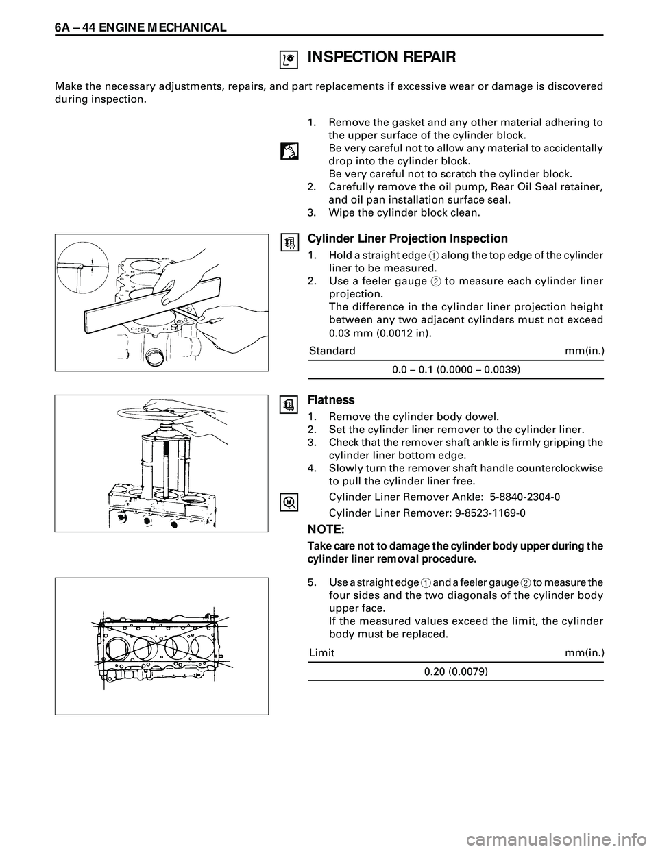
Cylinder Liner Projection Inspection
1. Hold a straight edge 1 along the top edge of the cylinder
liner to be measured.
2. Use a feeler gauge 2 to measure each cylinder liner
projection.
The difference in the cylinder liner projection height
between any two adjacent cylinders must not exceed
0.03 mm (0.0012 in).
0.0 – 0.1 (0.0000 – 0.0039)
mm(in.) Standard
Flatness
1. Remove the cylinder body dowel.
2. Set the cylinder liner remover to the cylinder liner.
3. Check that the remover shaft ankle is firmly gripping the
cylinder liner bottom edge.
4. Slowly turn the remover shaft handle counterclockwise
to pull the cylinder liner free.
Cylinder Liner Remover Ankle: 5-8840-2304-0
Cylinder Liner Remover: 9-8523-1169-0
NOTE:
Take care not to damage the cylinder body upper during the
cylinder liner removal procedure.
5. Use a straight edge 1 and a feeler gauge 2 to measure the
four sides and the two diagonals of the cylinder body
upper face.
If the measured values exceed the limit, the cylinder
body must be replaced.
0.20 (0.0079)
mm(in.) Limit
Page 2230 of 3573
7A±76
AUTOMATIC TRANSMISSION (4L30±E)
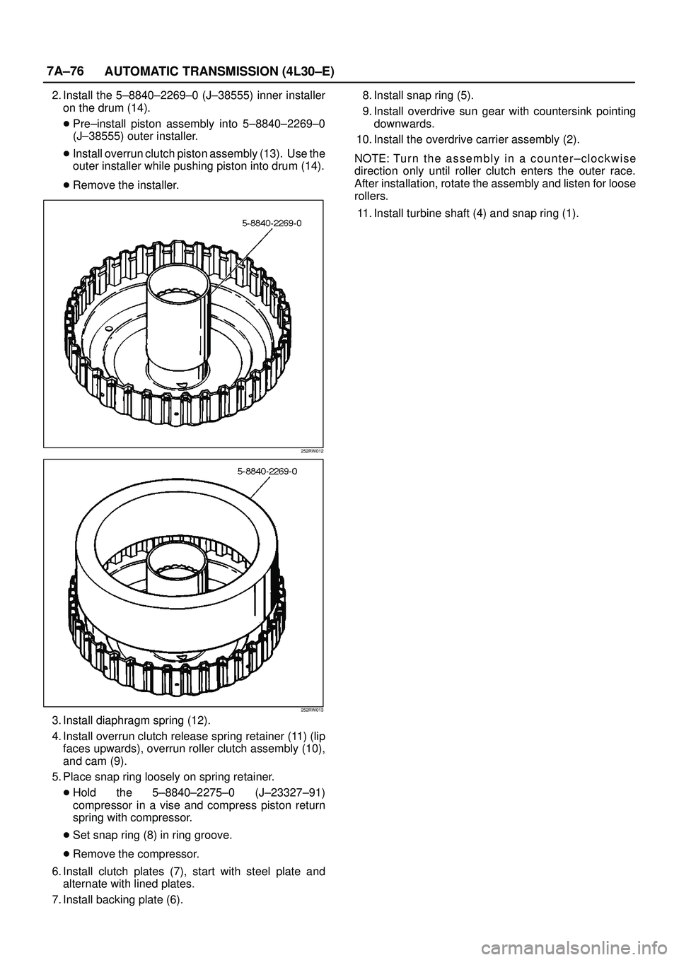
2. Install the 5±8840±2269±0 (J±38555) inner installer
on the drum (14).
�Pre±install piston assembly into 5±8840±2269±0
(J±38555) outer installer.
�Install overrun clutch piston assembly (13). Use the
outer installer while pushing piston into drum (14).
�Remove the installer.
252RW012
252RW013
3. Install diaphragm spring (12).
4. Install overrun clutch release spring retainer (11) (lip
faces upwards), overrun roller clutch assembly (10),
and cam (9).
5. Place snap ring loosely on spring retainer.
�Hold the 5±8840±2275±0 (J±23327±91)
compressor in a vise and compress piston return
spring with compressor.
�Set snap ring (8) in ring groove.
�Remove the compressor.
6. Install clutch plates (7), start with steel plate and
alternate with lined plates.
7. Install backing plate (6). 8. Install snap ring (5).
9. Install overdrive sun gear with countersink pointing
downwards.
10. Install the overdrive carrier assembly (2).
NOTE: Tu r n t h e a s sembly in a counter±clockwise
direction only until roller clutch enters the outer race.
After installation, rotate the assembly and listen for loose
rollers.
11. Install turbine shaft (4) and snap ring (1).
Page 2522 of 3573
CLUTCH7C±13
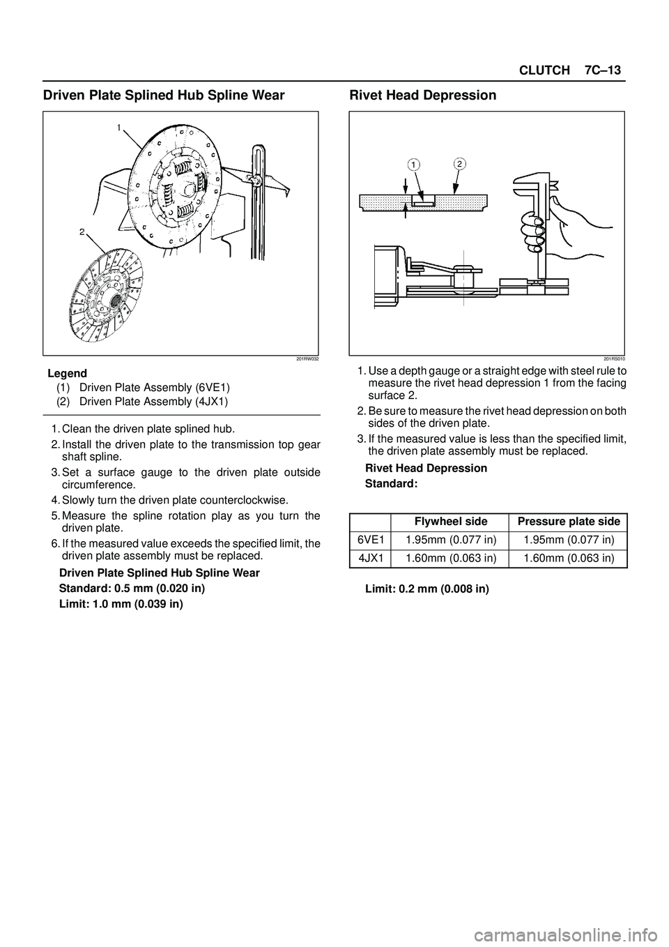
Driven Plate Splined Hub Spline Wear
201RW032
Legend
(1) Driven Plate Assembly (6VE1)
(2) Driven Plate Assembly (4JX1)
1. Clean the driven plate splined hub.
2. Install the driven plate to the transmission top gear
shaft spline.
3. Set a surface gauge to the driven plate outside
circumference.
4. Slowly turn the driven plate counterclockwise.
5. Measure the spline rotation play as you turn the
driven plate.
6. If the measured value exceeds the specified limit, the
driven plate assembly must be replaced.
Driven Plate Splined Hub Spline Wear
Standard: 0.5 mm (0.020 in)
Limit: 1.0 mm (0.039 in)
Rivet Head Depression
201RS010
1. Use a depth gauge or a straight edge with steel rule to
measure the rivet head depression 1 from the facing
surface 2.
2. Be sure to measure the rivet head depression on both
sides of the driven plate.
3. If the measured value is less than the specified limit,
the driven plate assembly must be replaced.
Rivet Head Depression
Standard:
Flywheel sidePressure plate side
6VE11.95mm (0.077 in)1.95mm (0.077 in)
4JX11.60mm (0.063 in)1.60mm (0.063 in)
Limit: 0.2 mm (0.008 in)