Page 1066 of 3573
ENGINE COOLING6B±13
Main Data and Specifications
General Specifications
M/TA/T
Cooling systemEngine coolant forced circulation
Radiator(1 tube in row) Tube type corrugated (2 tube in row)
Heat radiation capacity68,000 kcal/h77,000 kcal/h
Heat radiation area9.445m� (0.878ft�)11.21m� (1.04ft�)
Radiator front area0.302m� (0.028ft�)
Radiator dry weight39N (8.8lb)44N (9.9lb)
Radiator cap valve opening pressure93.3 ~ 122.7kpa (13.5 ~ 17.8psi)
Engine coolant capacity2.5lit (2.6U.S q.t.)2.4lit (2.5U.S q.t.)
Engine coolant pumpCentrifugal impeller type
Delivery300 (317) or more
Pump speed5000 + 50 rpm
ThermostatWax pellet type with air hole
Valve opening temperature74.5 ~ 78.5�C (166.1 ~ 173.3�F)
Engine coolant total capacity10.4lit (11.0U.S qt)10.5lit (11.1U.S qt)
Torque Specifications
N´m (Kg´m/lb ft)�
E06RW041
Page 1067 of 3573
6B±14
ENGINE COOLING
Special Tool
ILLUSTRATIONTOOL NO.
TOOL NAME
5±8840±0277±0
(J±24460±01)
Tester; radiator cap
5±8840±2603±0
(J±33984±A)
Adapter; radiator cap
Page 1510 of 3573

00 Ð 10 SERVICE INFORMATION
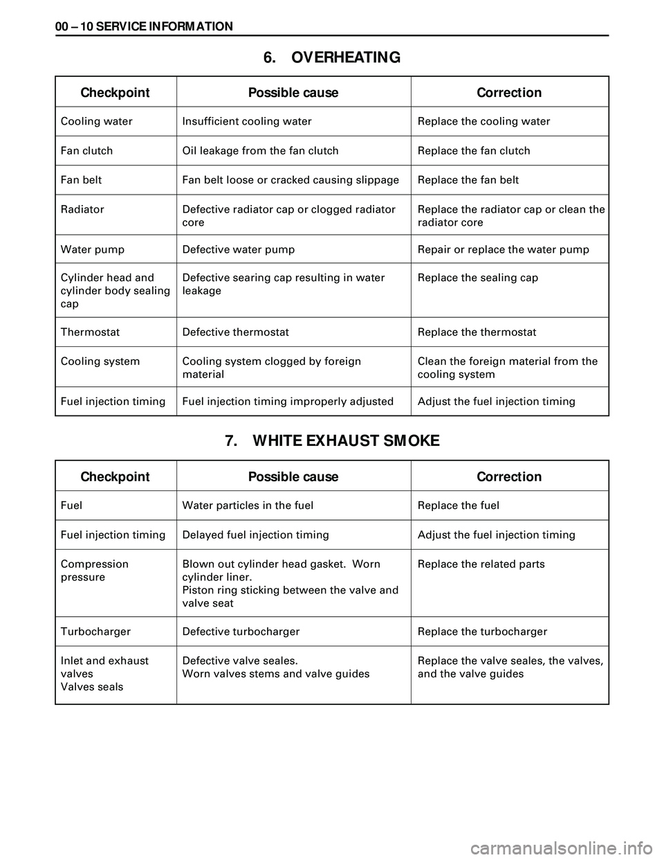
6. OVERHEATING
7. WHITE EXHAUST SMOKE
Checkpoint Possible cause Correction
Fuel Water particles in the fuel Replace the fuel
Fuel injection timing Delayed fuel injection timing Adjust the fuel injection timing
Compression
pressureBlown out cylinder head gasket. Worn
cylinder liner.
Piston ring sticking between the valve and
valve seatReplace the related parts
Turbocharger Defective turbocharger Replace the turbocharger
Inlet and exhaust
valves
Valves sealsDefective valve seales.
Worn valves stems and valve guidesReplace the valve seales, the valves,
and the valve guides
Checkpoint Possible cause Correction
Cooling water Insufficient cooling water Replace the cooling water
Fan clutch Oil leakage from the fan clutch Replace the fan clutch
Fan belt Fan belt loose or cracked causing slippage Replace the fan belt
Radiator Defective radiator cap or clogged radiator
coreReplace the radiator cap or clean the
radiator core
Water pump Defective water pump Repair or replace the water pump
Cylinder head and
cylinder body sealing
capDefective searing cap resulting in water
leakageReplace the sealing cap
Thermostat Defective thermostat Replace the thermostat
Cooling system Cooling system clogged by foreign
materialClean the foreign material from the
cooling system
Fuel injection timing Fuel injection timing improperly adjusted Adjust the fuel injection timing
Page 1514 of 3573
00 Ð 14 SERVICE INFORMATION
Condition Possible cause Correction
Engine overheating Low coolant level Replenish
Thermo unit faulty
Faulty thermostat
Faulty coolant unit
Clogged radiator
Faulty radiator cap
Low engine oil level or use of improper
engine oil
Damaged cylinder head gasket
Clogged exhaust system
Loose fan belt
Excessive fuel injected
Improper injection timing
Injection timing improper
Faulty thermostat
Faulty thermostatReplace
Replace
Repair or replace
Clean or replace
Replace
Replenish or change oil
Replenish
Replace
Clean exhaust system or replace
faulty parts
Adjust
Adjust
Adjust
Replace
Replace
Thermo unit faultyReplace Engine overcooling
Too long engine
warm-up time
Adjust
ENGINE COOLING TROUBLE
Page 1521 of 3573

SERVICE INFORMATION 00 Ð 21
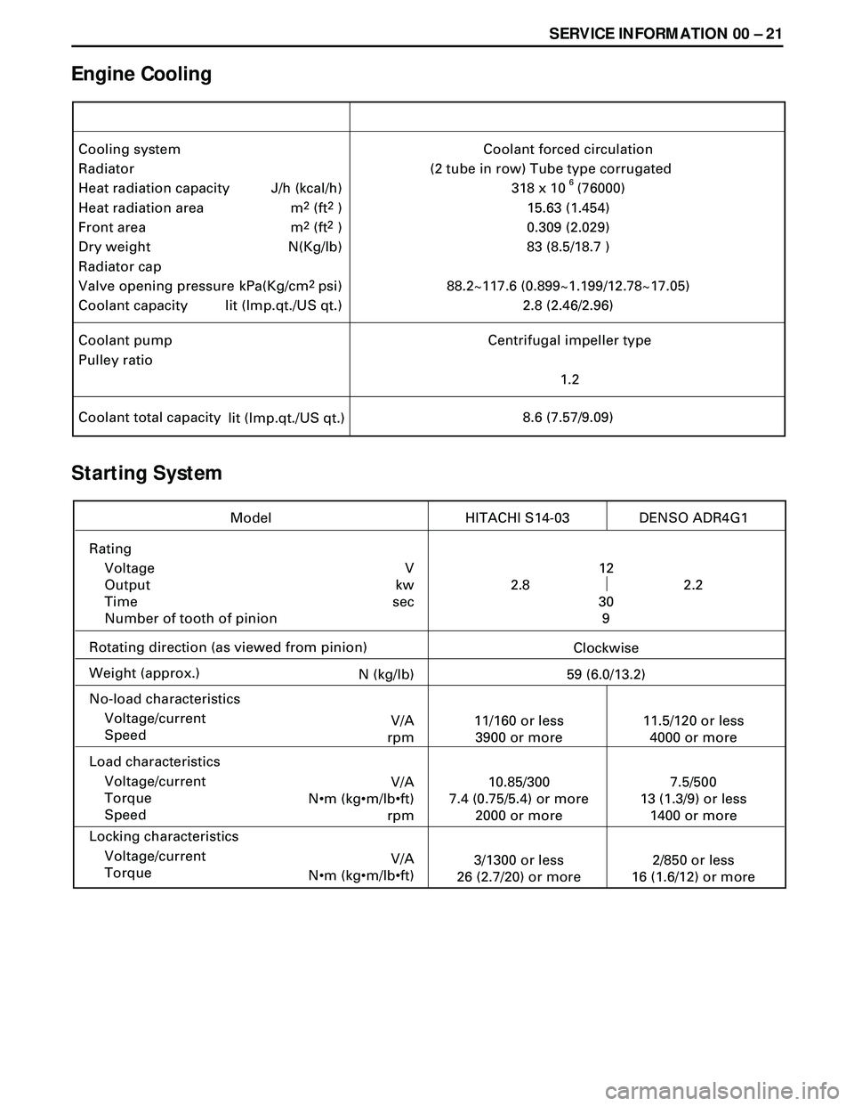
Engine Cooling
Starting System
Cooling system
Radiator
Heat radiation capacity
Heat radiation area
Front area
Dry weight
Radiator cap
Valve opening pressure
Coolant capacityCoolant forced circulation
(2 tube in row) Tube type corrugated
318 x 10 (76000)
15.63 (1.454)
0.309 (2.029)
83 (8.5/18.7 )
88.2~117.6 (0.899~1.199/12.78~17.05)
2.8 (2.46/2.96) J/h (kcal/h)
m
2 (ft2 )
m
2 (ft2 )
N(Kg/lb)
kPa(Kg/cm
2psi)
lit (Imp.qt./US qt.)
Coolant pump
Pulley ratioCentrifugal impeller type
1.2
Coolant total capacity
lit (Imp.qt./US qt.)8.6 (7.57/9.09)
6
Rating
Voltage
Output
Time
Number of tooth of pinion
Rotating direction (as viewed from pinion)
Weight (approx.)
No-load characteristics
Voltage/current
Speed
Load characteristics
Voltage/current
Torque
Speed
Locking characteristics
Voltage/current
Torque
Model HITACHI S14-03
V
kw
sec12
30
9
Clockwise
N (kg/lb)
59 (6.0/13.2)
V/A
rpm11/160 or less
3900 or more
V/A
N•m (kg•m/lb•ft)
rpm10.85/300
7.4 (0.75/5.4) or more
2000 or more
V/A
N•m (kg•m/lb•ft)3/1300 or less
26 (2.7/20) or more
11.5/120 or less
4000 or more
7.5/500
13 (1.3/9) or less
1400 or more
2/850 or less
16 (1.6/12) or more2.2 2.8DENSO ADR4G1
Page 1526 of 3573
00 Ð 26 SERVICE INFORMATION
Engine Cooling
mm (in)
mm (in)
Parts Items Service standardService limit Remarks
Cylinder liner
projection
Cylinder liner outside
diameter0.0-0.1
(0.00-0.0039)
97.011-97.050
(3.8193-3.8209) Cylinder
Block
(cont’ d)
Parts Items Service standardService limit Remarks
Valve opening
temperature
Valve full open
temperature and lift82¡C
(180¡F)
More than 10 (0.39)
at 95¡C (203¡F) Thermostat
Valve opening pressure 88.2 ~ 117.6kpa
(0.899 ~ 1.199kg/cm2/
12.8 ~ 17.0psi) Radiator
cap
Tension (Slackness)
AC generator & fan
pulley drive belt
A/C Compressor drive
belt
P/S pump drive beltNew belt
8-12 (0.31-0.47)
Used belt
8-12 (0.31-0.47)
New belt
7-10 (0.28-0.39)
Used belt
5-8 (0.2-0.31)
New belt
13-16 (0.51-0.63)
Used belt
13-16 (0.51-0.63) Drive belt
Page 1530 of 3573

00 Ð 30 SERVICE INFORMATION
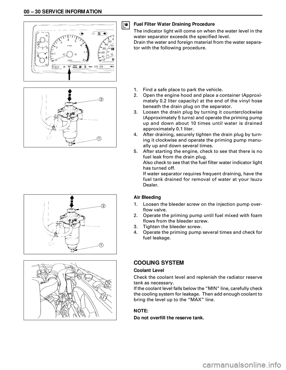
Fuel Filter Water Draining Procedure
The indicator light will come on when the water level in the
water separator exceeds the specified level.
Drain the water and foreign material from the water separa-
tor with the following procedure.
1. Find a safe place to park the vehicle.
2. Open the engine hood and place a container (Approxi-
mately 0.2 liter capacity) at the end of the vinyl hose
beneath the drain plug on the separator.
3. Loosen the drain plug by turning it counterclockwise
(Approximately 5 turns) and operate the priming pump
up and down about 10 times until water is drained
approximately 0.1 liter.
4. After draining, securely tighten the drain plug by turn-
ing it clockwise and operate the priming pump manu-
ally up and down several times.
5. After starting the engine, check to see that there is no
fuel leak from the drain plug.
Also check to see that the fuel filter water indicator light
has turned off.
If water separator requires frequent draining, have the
fuel tank drained for removal of water at your Isuzu
Dealer.
Air Bleeding
1. Loosen the bleeder screw on the injection pump over-
flow valve.
2. Operate the priming pump until fuel mixed with foam
flows from the bleeder screw.
3. Tighten the bleeder screw.
4. Operate the priming pump several times and check for
fuel leakage.
COOLING SYSTEM
Coolant Level
Check the coolant level and replenish the radiator reserve
tank as necessary.
If the coolant level falls below the ÒMINÓ line, carefully check
the cooling system for leakage. Then add enough coolant to
bring the level up to the ÒMAXÓ line.
NOTE:
Do not overfill the reserve tank.
Page 1531 of 3573

SERVICE INFORMATION 00 Ð 31
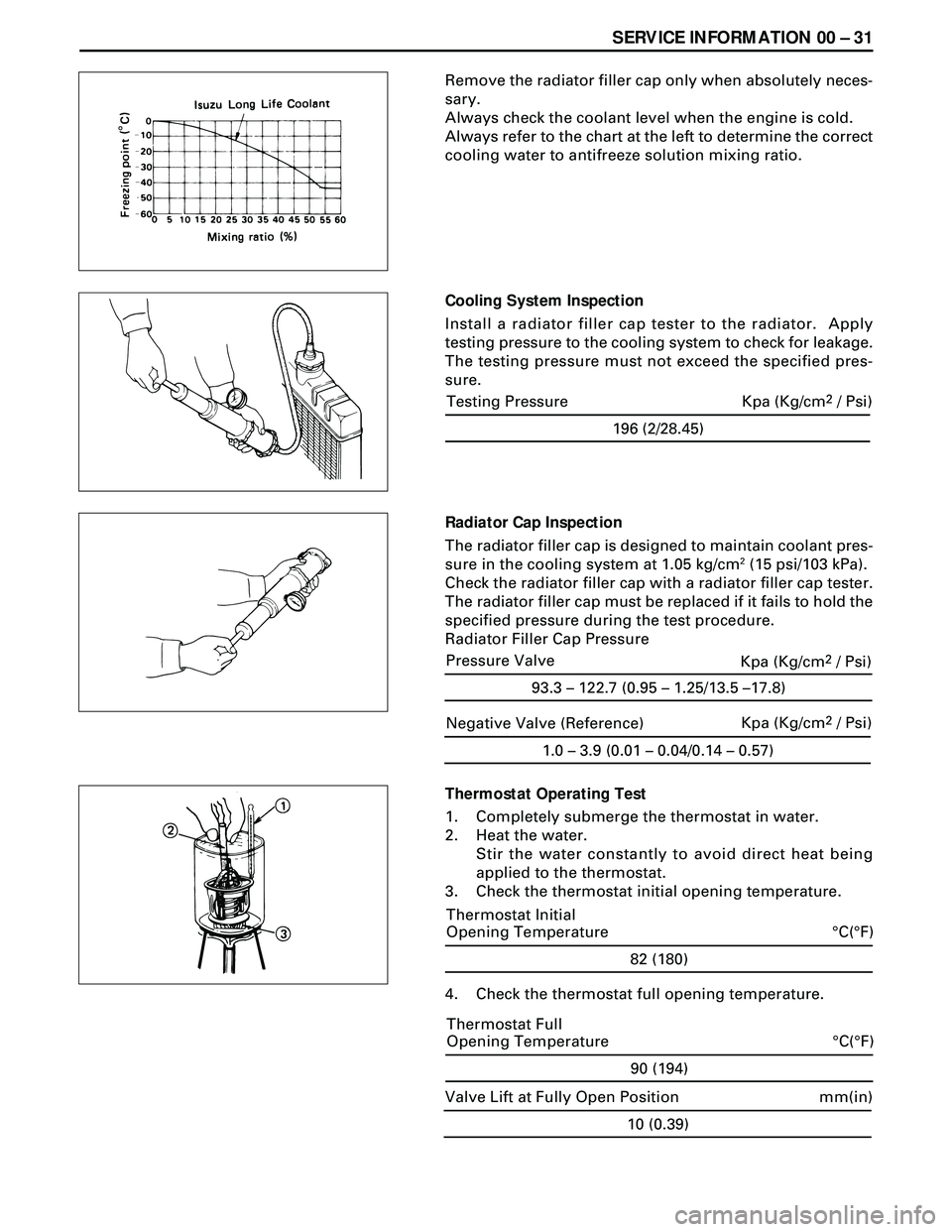
Remove the radiator filler cap only when absolutely neces-
sary.
Always check the coolant level when the engine is cold.
Always refer to the chart at the left to determine the correct
cooling water to antifreeze solution mixing ratio.
Cooling System Inspection
Install a radiator filler cap tester to the radiator. Apply
testing pressure to the cooling system to check for leakage.
The testing pressure must not exceed the specified pres-
sure.
Radiator Cap Inspection
The radiator filler cap is designed to maintain coolant pres-
sure in the cooling system at 1.05 kg/cm
2 (15 psi/103 kPa).
Check the radiator filler cap with a radiator filler cap tester.
The radiator filler cap must be replaced if it fails to hold the
specified pressure during the test procedure.
Radiator Filler Cap Pressure
Thermostat Operating Test
1. Completely submerge the thermostat in water.
2. Heat the water.
Stir the water constantly to avoid direct heat being
applied to the thermostat.
3. Check the thermostat initial opening temperature.
82 (180)
°C(°F) Thermostat Initial
Opening Temperature
4. Check the thermostat full opening temperature.
1.0 – 3.9 (0.01 – 0.04/0.14 – 0.57)
Negative Valve (Reference)Kpa (Kg/cm2 / Psi)
90 (194)
°C(°F) Thermostat Full
Opening Temperature
10 (0.39)
mm(in) Valve Lift at Fully Open Position
196 (2/28.45)
Testing Pressure Kpa (Kg/cm2 / Psi)
93.3 – 122.7 (0.95 – 1.25/13.5 –17.8)
Pressure Valve
Kpa (Kg/cm2 / Psi)