Page 909 of 3573

POWER ASSISTED BRAKE SYSTEM 5C – 31
•Operation
1) Outline
When the L.S.P.V. (Load Sensing Proportioning
Valve) detects a change in load weight, the load
sensing lever moves. Its reaction force is
transmitted to the bottom of the load sensing
valve to secure an optimum rear wheel cylinder
fluid pressure break point in proportion to the
actual load weight.
Besides, if the front brake system should fail, the
devices is designed to prevent the master cylinder
fluid pressure from decreasing and to apply it
directly to the rear wheel cylinder to obtain a
sufficient braking performance.
From rear
master cylinder
2) Operation
(1) When the fluid pressure is under the break point.
The fluid pressure of the rear master cylinder
passes through a clearance between the valve
seal and the piston and acts on the rear wheel
cylinder. At this moment, a downward force is
applied to the piston. However, the compression
spring force and reaction force of the load sensing
lever keep the piston in the upper position by
pushing upwards. (See the left figure.)To rear
wheel cylinder
(2) When the fluid pressure is equal to the break
point.
As the rear wheel cylinder pressure increases, it
surpasses the compression spring force and
reaction force of the load sensing lever, causing
the pistion to move downwards, so that the
pistion butts against the valve seal to shut off the
fluid line between the master cylinder and rear
wheel cylinder. (See the left figure.)
(3) When the fluid pressure is over the break point.
When the fluid pressure increases further, the
piston moves upwards. The moment the piston
comes apart from the valve seal, fluid pressure is
applied to the rear wheel cylinder and the piston
moves downwards so that the fluid line is shut off
again. This process goes on repeatedly to control
the fluid pressure to the rear wheel cylinder.
C05RW024 C05RW021 C05RW025
Page 910 of 3573

5C – 32 POWER ASSISTED BRAKE SYSTEM
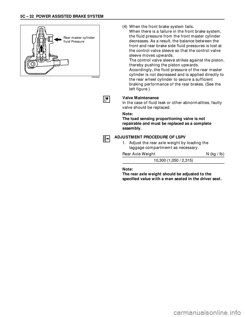
(4) When the front brake system fails.
When there is a failure in the front brake system,
the fluid pressure from the front master cylinder
decreases. As a result, the balance between the
front and rear brake side fluid pressures is lost at
the control valve sleeve so that the control valve
sleeve moves upwards.
The control valve sleeve strikes against the piston,
thereby pushing the piston upwards.
Accordingly, the fluid pressure of the rear master
cylinder is not decreased and is applied directly to
the rear wheel cylinder to secure a sufficient
braking performance of the rear brakes. (See the
left figure.)
Valve Maintenance
In the case of fluid leak or other abnormalities, faulty
valve should be replaced.
Note:
The load sensing proportioning valve is not
repairable and must be replaced as a complete
assembly.
ADJUSTMENT PROCEDURE OF LSPV
1. Adjust the rear axle weight by loading the
laggage compartmemt as necessary.
Rear Axle Weight N (kg / lb)
10,300 (1,050 / 2,315)
Note:
The rear axle weight should be adjusted to the
specified value with a man seated in the driver seat.
Rear master cylinder
fluid Pressure
C05RW022
Page 911 of 3573

POWER ASSISTED BRAKE SYSTEM 5C – 33
2. Check the rear wheel cylinder fluid pressure.
Install the pressure gauge on bleeder screws on
the front and rear brakes.
a. Depress the brake pedal slowly until the front
wheel cylinder fluid pressure reaches 7845 kPa
(80 kg/cm
2/ 114 psi)
Note:
•The brake pedal should be depressed
gradually until specified pressure is reached
without pumping or adjusting foot pressure.
•If the front wheel cylinder fluid pressure rises
abobe 7845 kPa (80 kg/cm
2/ 114 psi), release
the pedal fully, then depress the pedal again.
b. Hold the front wheel cylinder fluid pressure at
7845 kPa (80 kg/cm
2/ 114 psi) for 2 seconds,
check the rear wheel cylinder fluid pressure.
Rear wheel cylinder
fluid pressure kPa (kg/cm
2/ psi)
6374±539 (65±5.5 / 924±78)
c. If the rear wheel cylinder fluid pressure is not
within the specified range, adjust the fluid
pressure.
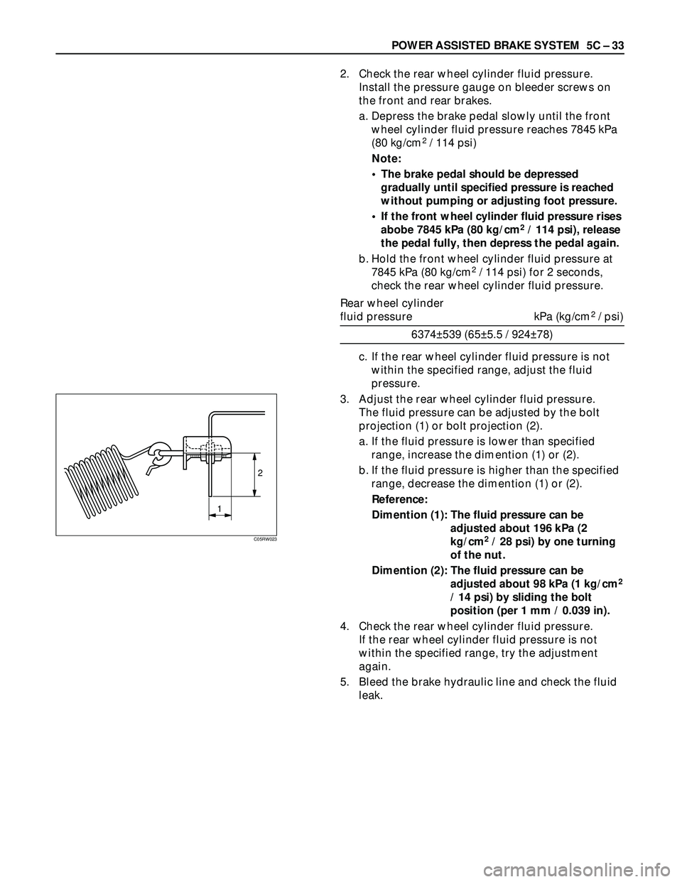
3. Adjust the rear wheel cylinder fluid pressure.
The fluid pressure can be adjusted by the bolt
projection (1) or bolt projection (2).
a. If the fluid pressure is lower than specified
range, increase the dimention (1) or (2).
b. If the fluid pressure is higher than the specified
range, decrease the dimention (1) or (2).
Reference:
Dimention (1): The fluid pressure can be
adjusted about 196 kPa (2
kg/cm
2/ 28 psi) by one turning
of the nut.
Dimention (2): The fluid pressure can be
adjusted about 98 kPa (1 kg/cm
2
/ 14 psi) by sliding the bolt
position (per 1 mm / 0.039 in).
4. Check the rear wheel cylinder fluid pressure.
If the rear wheel cylinder fluid pressure is not
within the specified range, try the adjustment
again.
5. Bleed the brake hydraulic line and check the fluid
leak.
2
1
C05RW023
Page 925 of 3573
POWER ASSISTED BRAKE SYSTEM 5C – 47
FRONT DISC BRAKE
BRAKE PADS REPLACEMENT
Outer side1
2
3
45
5
Removal Steps
1. Wheel and tire assembly
2. Lock bolt
3. Caliper assembly
4. Pad assembly with shim
5. Clip
Installation Steps
To install, follow the removal steps in the
reverse order.
REMOVAL
NOTE:
If a squealing noise occurs from the front brake while
driving, check the pad wear indicator plate. If the
indicator plate contacts the rotor, the disc pad
assembly should be replaced.
Preparation:
1) Draw out two-thirds of the brake fluid from the
reservoir.
2) Raise the vehicle and support it with suitable
safety stands.
1. Wheel and Tire Assembly
•Refer to Wheels and Tires in Suspension section.
Page 927 of 3573
POWER ASSISTED BRAKE SYSTEM 5C – 49
3. Caliper Assembly
1) Use adjustable pliers to bottom the piston into the
caliper bore. Be careful not to damage the piston
dust boot.
2) Do not damage the flexible hose by twisting or
pulling it.
2. Lock Bolt
Lock Bolt Torque N·m (kg·m / lb·ft)
74 (7.5 / 54)
1. Wheel and Tire Assembly
1) Refer to Wheels and Tires in Suspension section.
2) Pump the brake pedal several times to make sure
that the pedal is firm. Check the brake fluid level
in the reservoir after pumping the brakes.
Page 928 of 3573
5C – 50 POWER ASSISTED BRAKE SYSTEM
REMOVAL
Raise the vehicle and support with suitable safety
stands
1. Wheel and Tire Assembly
•Refer to Wheels and Tires in Suspension section.
2. Brake Flexible Hose
1) Remove the bolt and gaskets, then disconnect the
flexible hose from the caliper.
2) After disconnecting the flexible hose, cap or tape
the openings to prevent entry of foreign material.
3) Since the brake fluid flows out from the
connecting coupler, place a drain pan under the
vehicle.
CALIPER REPLACEMENT
Outer side
4
3
2
758
8
6
1
Removal Steps
1. Wheel and tire assembly
2. Brake flexible hose
3. Guide bolt
4. Lock bolt
5. Caliper assembly
6. Support bracket with pad assembly
7. Pad assembly with shim
8. Clip
Installation Steps
To install, follow the removal steps in the
reverse order.
Page 930 of 3573
5C – 52 POWER ASSISTED BRAKE SYSTEM
5. Caliper Assembly
4, 3. Lock Bolt and Guide Bolt
Lock Bolt and Guide Bolt Torque N·m (kg·m / lb·ft)
74 (7.5 / 54)
2. Brake Flexible Hose
1) Always use new gaskets.
2) Be sure to put the hooked edge of the flexible
hose end into the anti-rotation cavity.
Brake Flexible Hose Torque N·m (kg·m / lb·ft)
35 (3.5 / 26)
1. Wheel and Tire Assembly
1) Refer to Wheels and Tires in Suspension section.
2) Bleed brakes. Refer to Bleeding Brake Hydraulic
System in this section.
Hooked edge
Gasket
Page 934 of 3573
5C – 56 POWER ASSISTED BRAKE SYSTEM
REAR DISC BRAKE
BRAKE PADS REPLACEMENT
1
5
5
3
2
4
Removal Steps
1. Wheel and tire assembly
2. Lock bolt
3. Caliper assembly
4. Pad assembly with shim
5. Clip
Installation Steps
To install, follow the removal steps in the
reverse order.
REMOVAL
NOTE:
If a squealing noise occurs from the rear brake while
driving, check the pad wear indicator plate. If the
indicator plate contacts the rotor, the disc pad
assembly should be replaced.
1) Draw out two-thirds of the brake fluid from the
reservoir.
2) Raise the vehicle and support it with suitable
safety stands.
1. Wheel and Tire Assembly
•Refer to Wheels and Tires in Suspension section.
2. Lock Bolt