Page 1353 of 3573

6E±236
ENGINE DRIVEABILITY AND EMISSIONS
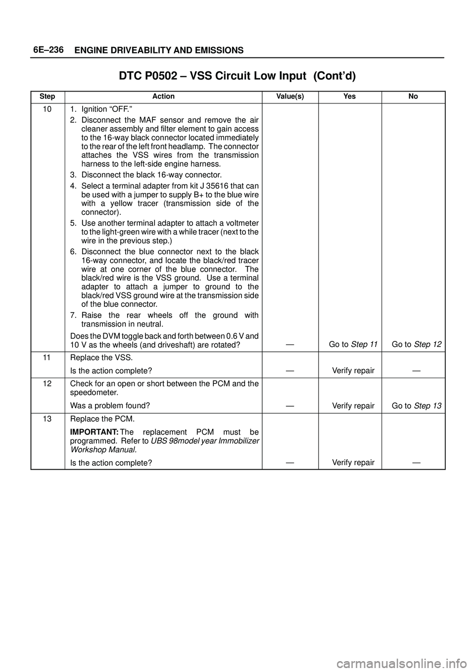
DTC P0502 ± VSS Circuit Low Input������ ���
StepNo Ye s Value(s) Action
101. Ignition ªOFF.º
2. Disconnect the MAF sensor and remove the air
cleaner assembly and filter element to gain access
to the 16-way black connector located immediately
to the rear of the left front headlamp. The connector
attaches the VSS wires from the transmission
harness to the left-side engine harness.
3. Disconnect the black 16-way connector.
4. Select a terminal adapter from kit J 35616 that can
be used with a jumper to supply B+ to the blue wire
with a yellow tracer (transmission side of the
connector).
5. Use another terminal adapter to attach a voltmeter
to the light-green wire with a while tracer (next to the
wire in the previous step.)
6. Disconnect the blue connector next to the black
16-way connector, and locate the black/red tracer
wire at one corner of the blue connector. The
black/red wire is the VSS ground. Use a terminal
adapter to attach a jumper to ground to the
black/red VSS ground wire at the transmission side
of the blue connector.
7. Raise the rear wheels off the ground with
transmission in neutral.
Does the DVM toggle back and forth between 0.6 V and
10 V as the wheels (and driveshaft) are rotated?
ÐGo to Step 11Go to Step 12
11Replace the VSS.
Is the action complete?
ÐVerify repairÐ
12Check for an open or short between the PCM and the
speedometer.
Was a problem found?
ÐVerify repairGo to Step 13
13Replace the PCM.
IMPORTANT:The replacement PCM must be
programmed. Refer to
UBS 98model year Immobilizer
Workshop Manual.
Is the action complete?ÐVerify repairÐ
Page 1416 of 3573

6E±299 ENGINE DRIVEABILITY AND EMISSIONS
damage, therefore, it is important to use care when
handling and testing electronic components.
NOTE: To prevent possible Electrostatic Discharge
damage, follow these guidelines:
�Do not touch the control module connector pins or
soldered components on the control module circuit
board.
�Do not open the replacement part package until the
part is ready to be installed.
�Before removing the part from the package, ground
the package to a known good ground on the vehicle.
�If the part has been handled while sliding across the
seat, or while sitting down from a standing position, or
while walking a distance, touch a known good ground
before installing the part.
NOTE: To prevent internal PCM damage, the ignition
must be in the ªOFFº position in order to disconnect or
reconnect power to the PCM (for example: battery cable,
PCM pigtail, PCM fuse, jumper cables, etc.).
IMPORTANT:When replacing the production PCM
with a service PCM, it is important to transfer the
broadcast code and production PCM number to the
service PCM label. This will allow positive identification of
PCM parts throughout the service life of the vehicle. Do
not record this information on the metal PCM cover.
IMPORTANT:The ignition should always be in the
ªOFFº position in order to install or remove the PCM
connectors.
Service of the PCM should normally consist of either re-
placement of the PCM or EEPROM programming. If the
diagnostic procedures call for the PCM to be replaced,
the PCM should be checked first to ensure it is the correct
part. If it is, remove the faulty PCM and install the new
service PCM.
The service PCM EEPROM will not be programmed.
DTC P0601 indicates the check sum error.
Removal Procedure
1. Disconnect the negative battery cable.
2. Block the wheels.
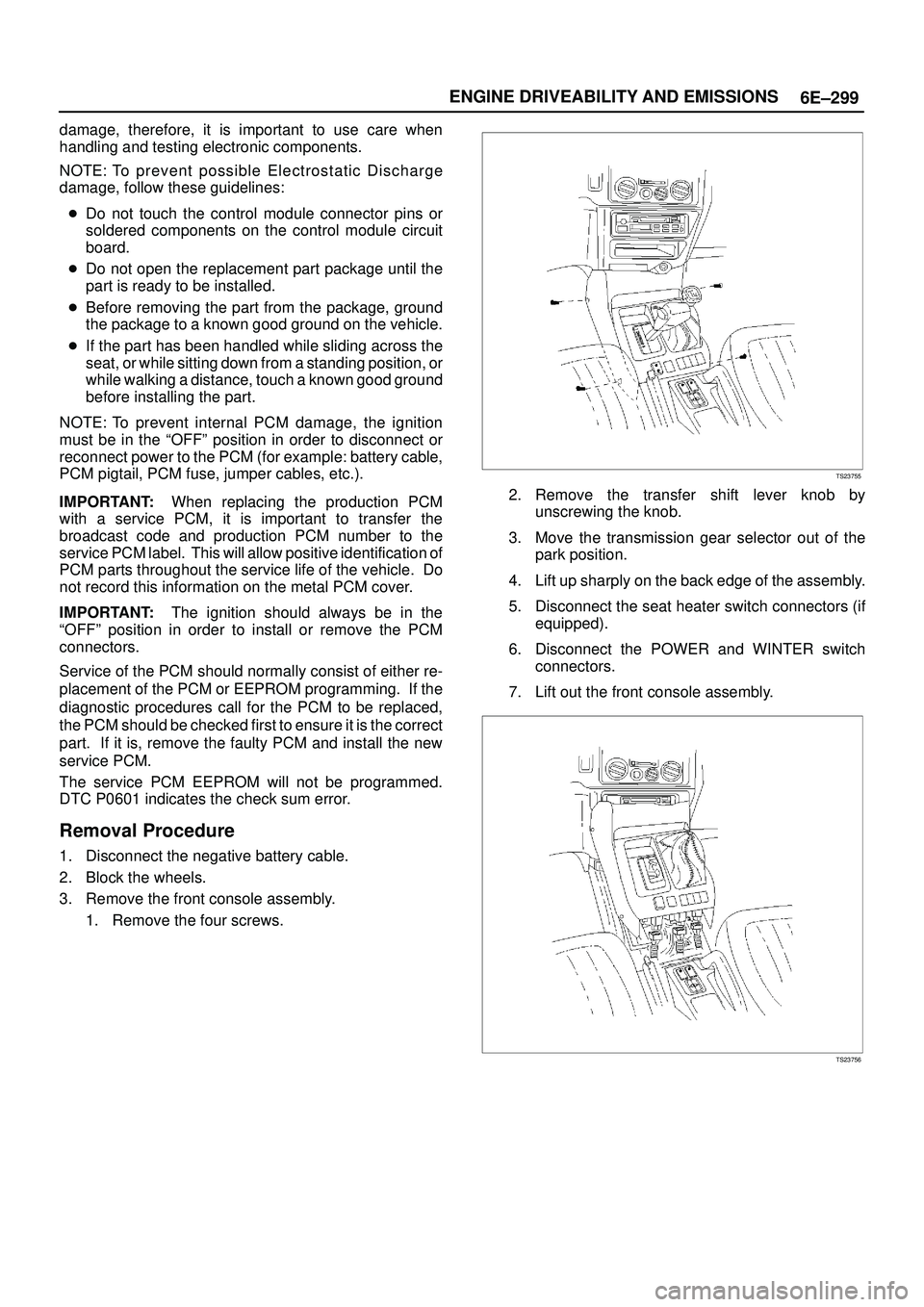
3. Remove the front console assembly.
1. Remove the four screws.
TS23755
2. Remove the transfer shift lever knob by
unscrewing the knob.
3. Move the transmission gear selector out of the
park position.
4. Lift up sharply on the back edge of the assembly.
5. Disconnect the seat heater switch connectors (if
equipped).
6. Disconnect the POWER and WINTER switch
connectors.
7. Lift out the front console assembly.
TS23756
Page 1486 of 3573

6G±7 ENGINE LUBRICATION
Oil Pan and Crankcase
Removal
1. Disconnect battery ground cable.
2. Drain engine oil.
3. Lift vehicle by supporting the frame.
4. Remove front wheels.
5. Remove oil level dipstick from level gauge tube.
6. Remove stone guard.
7. Remove radiator under fan shroud.
8. Remove suspension cross member fixing bolts, 2 pcs
each per side and remove suspension cross member.
9. Remove pitman arm and relay lever assembly, using
the 5±8840±2005±0 remover, remove pitman arm
from the steering unit and remove four fixing bolts for
relay lever assembly.
10. Remove axle housing assembly four fixing bolts from
housing isolator side and mounting bolts from wheel
side. At this time support the axle with a garage jack
and remove axle housing assembly.
11. Remove oil pan fixing bolts.
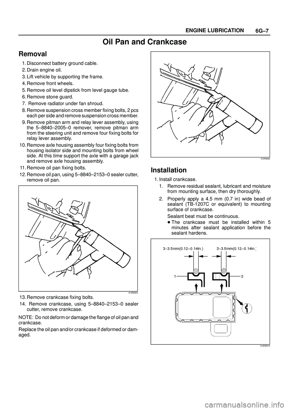
12. Remove oil pan, using 5±8840±2153±0 sealer cutter,
remove oil pan.
013RS003
13. Remove crankcase fixing bolts.
14. Remove crankcase, using 5±8840±2153±0 sealer
cutter, remove crankcase.
NOTE: Do not deform or damage the flange of oil pan and
crankcase.
Replace the oil pan and/or crankcase if deformed or dam-
aged.
013RS003
Installation
1. Install crankcase.
1. Remove residual sealant, lubricant and moisture
from mounting surface, then dry thoroughly.
2. Properly apply a 4.5 mm (0.7 in) wide bead of
sealant (TB-1207C or equivalent) to mounting
surface of crankcase.
Sealant beat must be continuous.
�The crankcase must be installed within 5
minutes after sealant application before the
sealant hardens.
013RW010
Page 1513 of 3573
SERVICE INFORMATION 00 Ð 13
Checkpoint Possible cause Correction 4. SLAPPING NOISE
Valve clearance Valve clearance improperly adjusted Adjust the valve clearance
Rocker arm Damaged rocker arm Replace the rocker arm
Flywheel Loose flywheel bolts Retighten the flywheel bolts
Crankshaft and
thrust bearingsWorn or damaged crankshaft and/or
thrust bearingsReplace the crankshaft and/or the
thrust bearings
Crankshaft and
connecting rod
bearingsWorn or damaged crankshaft and/or
connecting rod bearingsReplace the crankshaft and/or the
connecting rod bearings
Connecting rod
bushing and piston
pinWorn or damaged connecting rod bushing
and piston pinReplace the connecting rod bushing
and/or the piston pin
Piston and cylinder
linerWorn or damaged piston and cylinder liner.
Foreign material in the cylinder.Replace the piston and the cylinder
liner.
Page 1533 of 3573

SERVICE INFORMATION 00 Ð 33
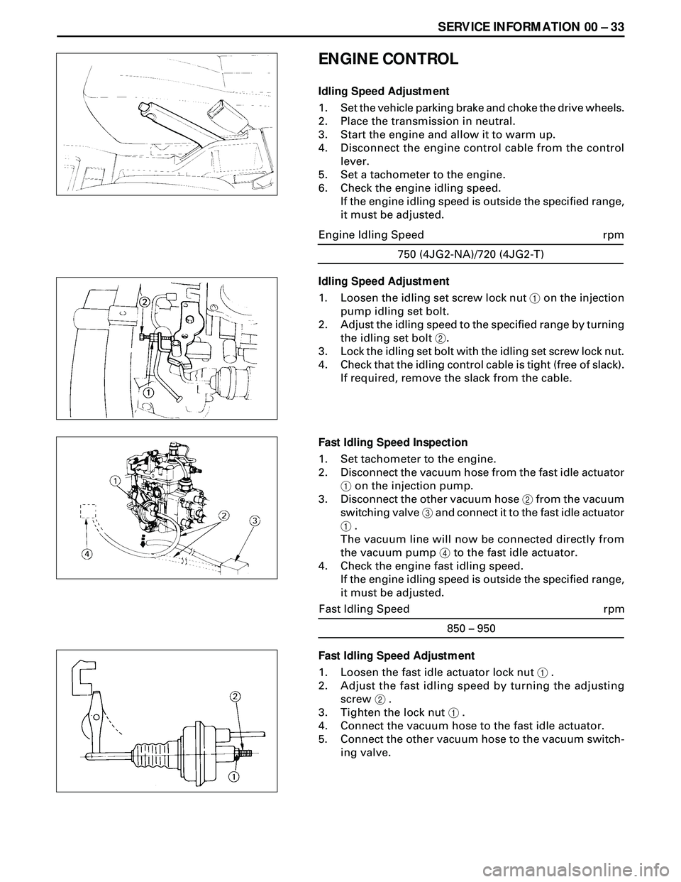
ENGINE CONTROL
Idling Speed Adjustment
1. Set the vehicle parking brake and choke the drive wheels.
2. Place the transmission in neutral.
3. Start the engine and allow it to warm up.
4. Disconnect the engine control cable from the control
lever.
5. Set a tachometer to the engine.
6. Check the engine idling speed.
If the engine idling speed is outside the specified range,
it must be adjusted.
Fast Idling Speed Adjustment
1. Loosen the fast idle actuator lock nut 1 .
2. Adjust the fast idling speed by turning the adjusting
screw 2 .
3. Tighten the lock nut 1 .
4. Connect the vacuum hose to the fast idle actuator.
5. Connect the other vacuum hose to the vacuum switch-
ing valve.750 (4JG2-NA)/720 (4JG2-T)
rpm Engine Idling Speed
Idling Speed Adjustment
1. Loosen the idling set screw lock nut 1 on the injection
pump idling set bolt.
2. Adjust the idling speed to the specified range by turning
the idling set bolt 2.
3. Lock the idling set bolt with the idling set screw lock nut.
4. Check that the idling control cable is tight (free of slack).
If required, remove the slack from the cable.
Fast Idling Speed Inspection
1. Set tachometer to the engine.
2. Disconnect the vacuum hose from the fast idle actuator
1 on the injection pump.
3. Disconnect the other vacuum hose 2 from the vacuum
switching valve 3 and connect it to the fast idle actuator
1 .
The vacuum line will now be connected directly from
the vacuum pump 4 to the fast idle actuator.
4. Check the engine fast idling speed.
If the engine idling speed is outside the specified range,
it must be adjusted.
850 – 950
rpm Fast Idling Speed
Page 1539 of 3573
SERVICE INFORMATION 00 Ð 39
Crankshaft Bearing Cap, Connecting Rod Bearing Cap, Crankshaft Damper
Pulley, Flywheel, Crank Case
Nám (Kgám/lbáft)
Page 1564 of 3573
6A Ð 14 ENGINE MECHANICAL
CAMSHAFT, TAPPET
6. Camshaft Timing Gear
·Install the stopper bolt 1 to the timing pulley to
prevent it from turning.
·Use the timing pulley puller 2 to remove the
pulley.
Camshaft Timing Pulley Puller: 5-8840-0086-0
7. Camshaft Thrust Plate
DISASSEMBLY
1. Cylinder Head Assembly
2. Flywheel
3. Cylinder Block rear Plate
4. Crankcase Assembly
5. Oil Pump Assembly
Page 1568 of 3573
6A Ð 18 ENGINE MECHANICAL
8. Camshaft
1) Apply a coat of engine oil to the camshaft and the
camshaft bearings.
Install the camshaft to the cylinder body.
Take care not to damage the camshaft bearings.
7. Camshaft Thrust Plate
Install the thrust plate to the cylinder body and tighten the
thrust plate bolts to specified torque.
6. Camshaft Timing Gear
1) Install the camshaft timing gear to the camshaft.
The timing gear mark ("Y - Y") must be facing out-
ward.
2) Tighten the timing gear to the specified torque.
5. Oil Pump Assembly
¥ Refer to Section 6A2 ÒOil Pump InstallationÓ.
4. Crankcase Assembly
¥ Refer to Section 6A2 ÒCrankcaseÓ.
3. Cylinder Block Rear Plate
¥ Tighten cylinder block rear plate fixing bolts to the
specified torque.
18 (1.8/13)N·m(Kg·m/lb·ft)
64 (6.5/47)N·m(Kg·m/lb·ft)
82 (8.4/61)N·m(kg·m/lb·ft)
2. Flywheel
¥ Refer to Section 6A2 ÒCrankshaft InstallationÓ.
1. Cylinder Head Assembly
¥ Refer to Section 6A2 ÒCylinder Head InstallationÓ.