Page 1841 of 3573
6B – 8 ENGINE COOLING
INSTALLATION
1. Thermostat
1) The jiggle valve of the thermostat must face the
cylinder head side.
2. Gasket
3. Install thermostat housing and tighten bolt to the
specified torque.
Torque: 20 N·m (2.0 kg·m/14.5 lb ft)
4. Reconnect water hose
1) Fill coolant to full level.
2) Reconnect battery ground cable.
5. Start the engine check for coolant leakage.
Page 1847 of 3573
6C – 2 ENGINE FUEL
FUEL FLOW
1
14 Except above region
89
10111
2
2
4
12
5 6
7
3
13
14 For Europe, Nicaragua,
Argentina, Philippin
11
4
Legend
(1) Fuel Filler Cap
(2) Fuel Tank
(3) Rollover Valve
(4) Fuel Supply Pipe
(5) Fuel Filter with Priming Pump
(6) Fuel Pump
(7) High Pressure Oil Pump(8) Cylinder Head
(9) Injector
(10) Orifice
(11) Fuel Return Pipe
(12) Fuel Tank Pressure Release Hose
(13) Intake Air Duct
(14) Fuel Tank Pressure Control Valve
040R200001
Page 1855 of 3573

6C – 10 ENGINE FUEL
REMOVAL
Prior to removal, be sure to confirm and record the
group code of the injector installed using Tech2.
1. Disconnect battery ground cable.
2. Remove air cleaner cover and air duct.
3. Remove intercooler.
Refer to “Intercooler” in this manual.
4. Remove PCV hose and pipe.
5. Remove cylinder head noise insulator cover.
6. Remove high pressure oil pipe.
CAUTION:
1) Sleeve nut should be loosened with cloth tied
around to prevent oil from spurting due to the
remaining pressure.
2) High oil pressure pipe should be disconnected
with cloth tied around the intake manifold glow
plug to prevent oil from flowing out of the oil
rail.
7. Loosen eye bolt of fuel pipe at fuel pump side.
NOTE: Cloth should be put around the loosened eye
bolt to prevent fuel from flowing out.
8. Remove fuel return hose at chassis side.
9. Remove PCV hose to cylinder head cover.
10. Remove cylinder head cover.
11. Drain the oil from oil rail assembly.
NOTE: Do not drop O-ring
12. Record the grade code of injector for each cylinder
that is indicated on the upper portion of injector.
There are nine kinds of grade code available, one
alphabet letter and one numeral letter.
Grade codeLegend
(1) Part Number
(2) Category Number (Grade code)
(3) Serial Number
(4) Bar Code
13. Remove harness connector from each injector.
14. Loosen nuts and bolts for oil rail.
15. Remove injector fixing bolts.
16. Remove injector clamp.
17. Remove injector assembly.
INSTALLATION
1. Install oil rail, tighten temporarily
2. Install injector assembly.
NOTE:
1) Do not forget to install O-ring between injector and
oil rail.
2) Use new O-ring
3) Clean O-ring groove and fitting surface of parts.
4) Apply engine oil to O-ring.
3. Install injector fixing bolts, tighten temporarily.
4. Install injector clamp, tighten nut temporarily.
5. Tighten injector fixing bolts to the specified torque.
Torque: 6.5 N·m (0.7 kg·m / 5.1 lb ft)
6. Tighten injector clamp nut to the specified torque
with special method.
Torque: 30 N·m (3.1 kg·m / 22.4 lb ft) then loosen a
time again tighten as following torque.
Torque: 25 N·m (2.4 kg·m / 17.4 lb ft)
7. Tighten oil rail to the specified torque.
Torque: 20 N·m (2.0 kg·m / 14.5 lb ft)
1
4
32
055RW00001
Category number
A– 1
A– 2
A– 3
B – 1
B – 2
B – 3
C – 1
C – 2
C – 3
Page 1856 of 3573

ENGINE FUEL 6C – 11
8. Install injector harness assembly, reconnect
harness connecter to injector.
9. Record the identification marking of injector for
each cylinder that is indicated on the upper portion
of injector.
Legend
(1) Part Number
(2) Category Number (Grade code)
(3) Serial Number
(4) Bar Code
10. Install cylinder head assembly.
Refer to “Cylinder Head” in this manual.
11. Fill with about 300cc of engine oil from the high
pressure oil pipe installation port of the oil rail using
an oil filler.
If assembled without filling the oil rail with oil, the
time for engine starting will be longer.
12. Immediately install high pressure oil pipe and
tighten to specified torque.
Torque: 80 N·m (8.1 kg·m / 57.9 lb ft)
13. Install cylinder head noise insulator cover.
Refer to “Cylinder Head” in this manual.
14. Install intercooler assembly.
Refer to “Intercooler” in this manual.
15. Install air cleaner cover and air duct.
16. Use TECH2 to rewrite injector data to ECM.
For rewriting method refer to section “Data
Programming in Case of ECM Change” of section
6E 4JX1 engine driveability and emissions in this
manual.NOTE:
1) On completion of servicing, bleed air from the
engine inside fuel passage by means of the priming
pump. (The priming pump should be operated more
times than in the case of conventional engines.)
2) As air is in the oil rail, it takes more time to start the
engine. Rough idling may occur while the air is
being bled completely after engine start, but it does
not indicate trouble.
The air will be bled and normal engine status will be
reached while the vehicle is driven for about 5 km
or engine is operated for about 5 minutes at 1500 to
2000 rpm.
3) The injector spare part will be provided for group
number B1, B2 and B3 only.
Injector Grade code Programming
(Injector Change)
In case of an injector change, the injector grade code
(category number) must be programmed by Tech-2.
Programming Procedure
1. Connect the Tech-2 to the vehicle DLC.
2. Turn the starter switch to the “ON” position.
3. Select the “Diagnosis” from the Main menu.
4. Select the “Programming” from the Application
menu.
1
4
32
055RW00001
F0 : �%�J�B�H�O�P�T�U�J�D���$�P�E�F
F1 : �%�B�U�B���%�J�T�Q�M�B�Z
F2 : �4�O�B�Q�T�I�P�U
F3 : �.�J�T�D�F�M�M�B�O�F�P�V�T���5�F�T�U
F4 : �1�S�P�H�S�B�N�N�J�O�H�"�Q�Q�M�J�D�B�U�J�P�O���.�F�O�V
035RW00002
Page 1863 of 3573

7")
6C – 18 ENGINE FUEL
4. Remove lock bolt of idle gear A.
5. Install timing gear case cover.
Refer to “Timing gear” in this manual.
6. Install front plate.
Torque: 20 N·m (2.0 kg·m/14.5 lb ft)
7. Install timing pulley of high pressure oil pump.
Torque: 10 N·m (1.0 kg·m/7.2 lb ft)
8. Install timing belt and tighten timing belt tensioner
assembly.
Refer to “Cylinder head” in this manual.
Legend
(1) Align Mark
(2) Camshaft Pulley
(3) Timing Belt
(4) High Pressure Oil Pump Pulley
(5) Bolt
(6) Tensioner Assembly
(7) Tensioner Bolt
(8) Tensioner Spring
9. Install CMP sensor bracket.
Torque: 20 N·m (2.0 kg·m/14.5 lb ft)
10. Connect CMP sensor cable.
11. Install timing belt cover.
Torque: 9 N·m (0.9 kg·m/6.5 lb ft)
12. Fill with about 300 cc of engine oil from the high
pressure oil pipe installation port of the oil rail using
an oil filler.
If assembled without filling the oil rail with oil, the
time for engine starting will be longer.
13. Immediately install high pressure oil pipe and
tighten to specified torque.
NOTE:
1) Use new O-ring.
2) Clean O-ring groove and fitting surface of parts.
3) Apply engine oil to O-ring.
Torque: 80 N·m (8.1 kg·m/57.9 lb ft)14. Install the crankshaft damper pulley with specified
torque.
Torque: 220 N·m (22 kg·m/159 lb ft)
15. Install the intercooler assembly.
Refer to “Intercooler” in this manual.
16. Install air cleaner cover and air duct.
1
2
3
8
67
4 5
F06RW055
Page 1912 of 3573
 SensorAP Bracket
2CKP (Crankshaft Positi")
6E±19 4JX1±TC ENGINE DRIVEABILITY AND EMISSIONS
Component Locator
Engine Component Locator Table
F06RW051
NumberNameLocation
1AP (Accelerator Pedal Position) SensorAP Bracket
2CKP (Crankshaft Position) SensorInside the right front flywheel Housing
3Oil RailMounted on the camshaft carrier
4Oil (Rail) Pressure SensorMounted on the Oil Rail
5OT (Oil Temperature) SensorMounted on the Oil Rail
6Fuel InjectorIn the Cylinder Head Cover
7Fuel Return OrificeInside the Cylinder Head
8FT (Fuel Temperature) SensorFuel Return Adaptor
9IntercoolerOn the Cylinder Head Cover
10Intake Throttle MotorBehind the Intake Manifold
11Intake ThrottleBehind the Intake Manifold
122 Way Check ValveBelow the Intake Manifold
13VSV (Vacuum Switching Valve)At the left Cylinder Body
14EGR Pressure SensorBelow the Intake Manifold
15Fuel FilterAt the left Engine Room
16CMP (Camshaft Position) SensorOn the forward of Timing Gear Case
17IAT (Intake Air Temperature) SensorBelow the Intake Manifold
18ECT (Engine Coolant Temperature)Thermostat Housing
19High Pressure Oil PumpOn the back Timing Gear Case
Page 2071 of 3573
6E±178
4JX1±TC ENGINE DRIVEABILITY AND EMISSIONS
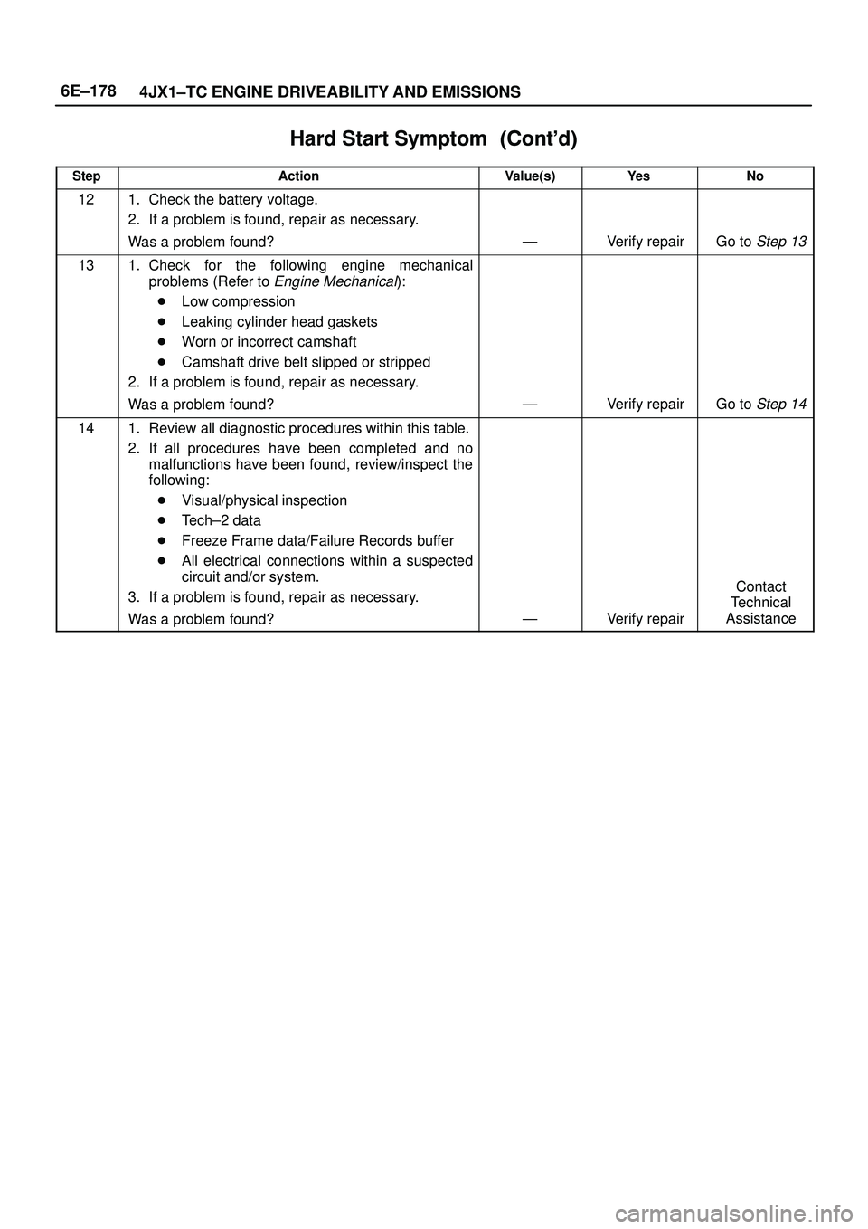
Hard Start Symptom������ ���
StepNo Ye s Value(s) Action
121. Check the battery voltage.
2. If a problem is found, repair as necessary.
Was a problem found?
ÐVerify repairGo to Step 13
131. Check for the following engine mechanical
problems (Refer to
Engine Mechanical):
�Low compression
�Leaking cylinder head gaskets
�Worn or incorrect camshaft
�Camshaft drive belt slipped or stripped
2. If a problem is found, repair as necessary.
Was a problem found?
ÐVerify repairGo to Step 14
141. Review all diagnostic procedures within this table.
2. If all procedures have been completed and no
malfunctions have been found, review/inspect the
following:
�Visual/physical inspection
�Tech±2 data
�Freeze Frame data/Failure Records buffer
�All electrical connections within a suspected
circuit and/or system.
3. If a problem is found, repair as necessary.
Was a problem found?
ÐVerify repair
Contact
Technical
Assistance
Page 2088 of 3573
6E±195 4JX1±TC ENGINE DRIVEABILITY AND EMISSIONS
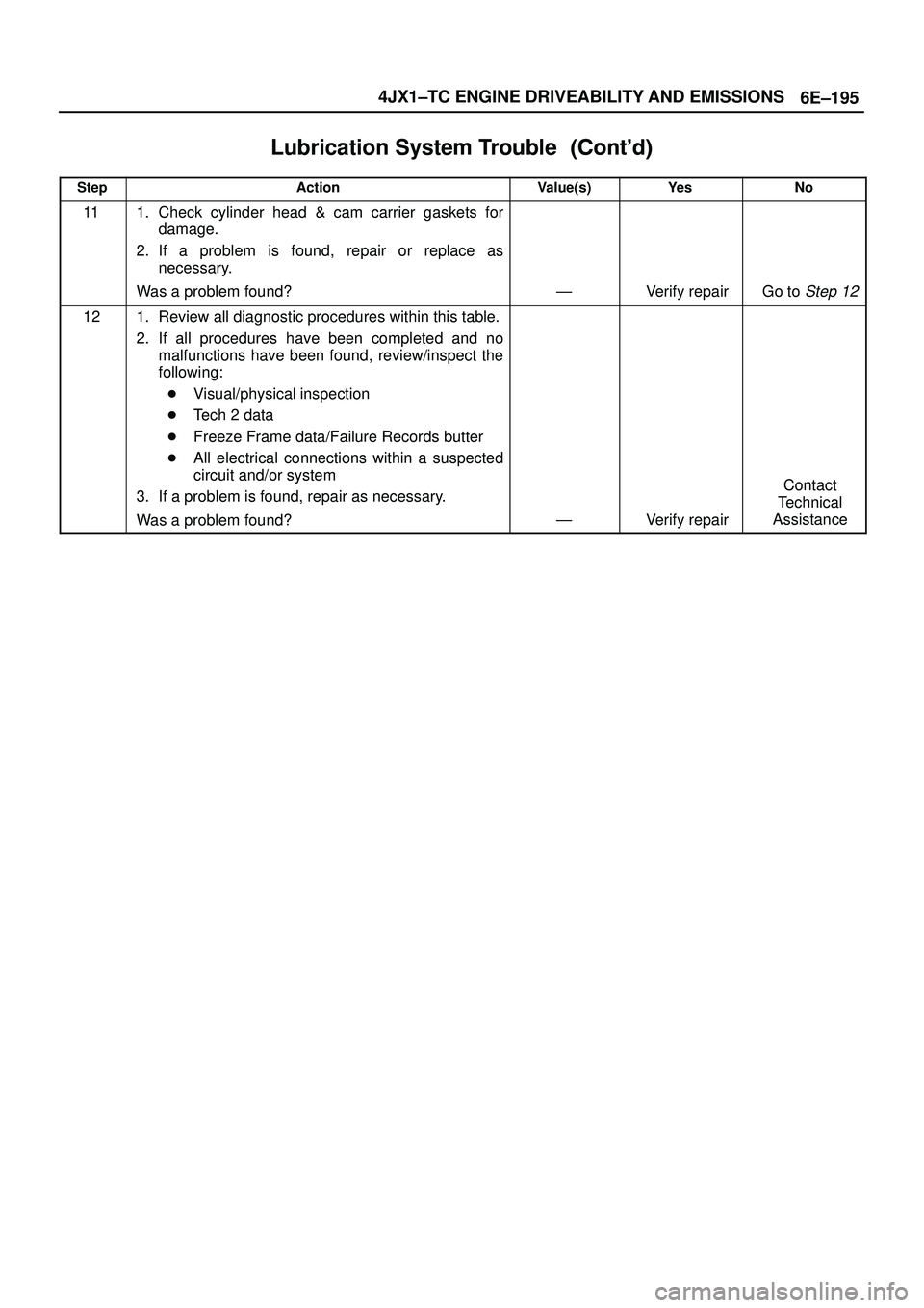
Lubrication System Trouble������ ���
StepNo Ye s Value(s) Action
111. Check cylinder head & cam carrier gaskets for
damage.
2. If a problem is found, repair or replace as
necessary.
Was a problem found?
ÐVerify repairGo to Step 12
121. Review all diagnostic procedures within this table.
2. If all procedures have been completed and no
malfunctions have been found, review/inspect the
following:
�Visual/physical inspection
�Tech 2 data
�Freeze Frame data/Failure Records butter
�All electrical connections within a suspected
circuit and/or system
3. If a problem is found, repair as necessary.
Was a problem found?
ÐVerify repair
Contact
Technical
Assistance
 The jiggle valve of the thermostat must face the
cylinder head side.
2. Gasket
3. Install thermostat housing and tighten bolt to the
specified tor")
 Fuel Filler Cap
(2) Fuel Tank
(3) Rollover Valve
(4)")