Page 79 of 3573

00 Ð 40 SERVICE INFORMATION
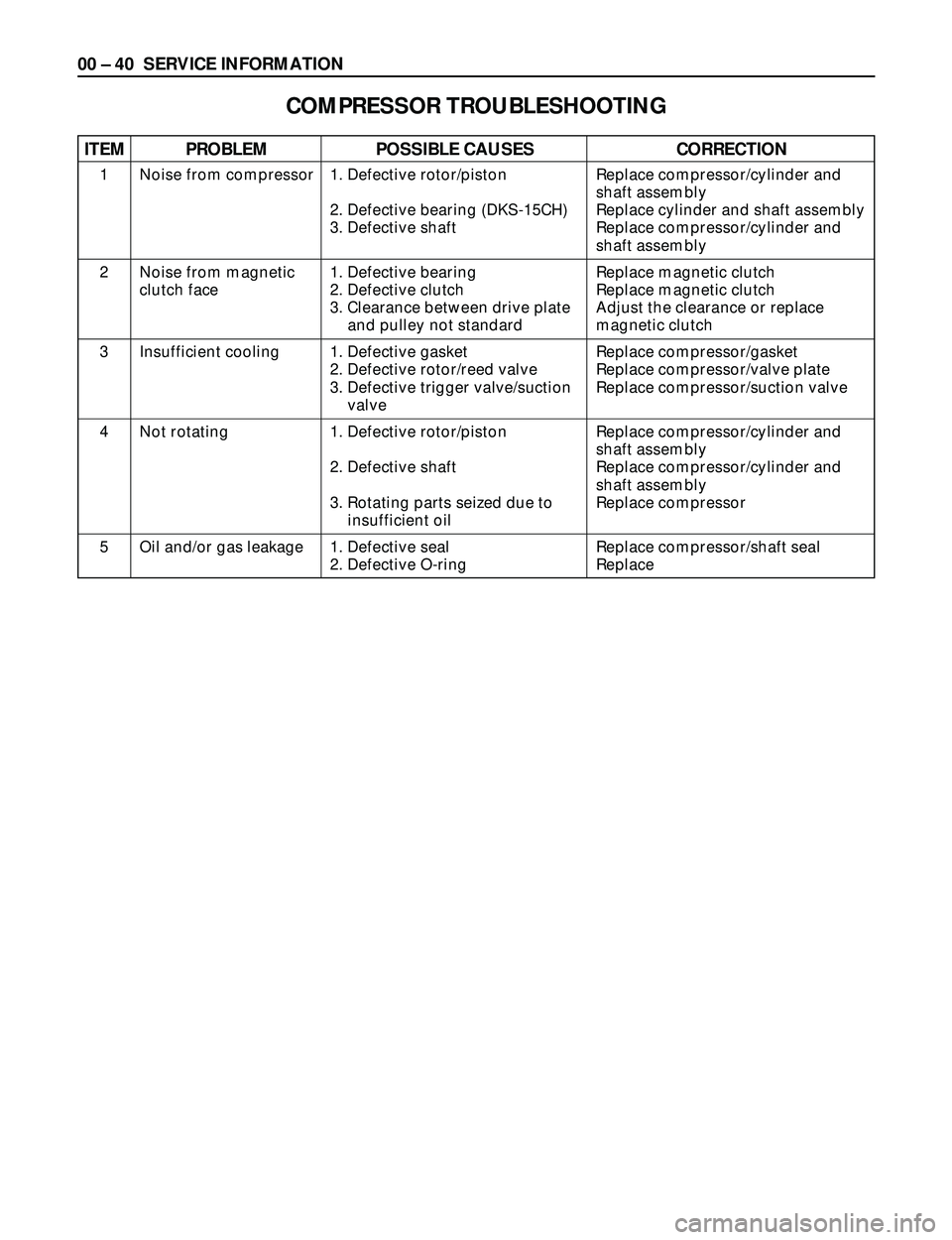
1. Defective rotor/piston
2. Defective bearing (DKS-15CH)
3. Defective shaft
1. Defective bearing
2. Defective clutch
3. Clearance between drive plate
and pulley not standard
1. Defective gasket
2. Defective rotor/reed valve
3. Defective trigger valve/suction
valve
1. Defective rotor/piston
2. Defective shaft
3. Rotating parts seized due to
insufficient oil
1. Defective seal
2. Defective O-ringReplace compressor/cylinder and
shaft assembly
Replace cylinder and shaft assembly
Replace compressor/cylinder and
shaft assembly
Replace magnetic clutch
Replace magnetic clutch
Adjust the clearance or replace
magnetic clutch
Replace compressor/gasket
Replace compressor/valve plate
Replace compressor/suction valve
Replace compressor/cylinder and
shaft assembly
Replace compressor/cylinder and
shaft assembly
Replace compressor
Replace compressor/shaft seal
Replace Noise from compressor
Noise from magnetic
clutch face
Insufficient cooling
Not rotating
Oil and/or gas leakage 1
2
3
4
5
ITEM PROBLEM POSSIBLE CAUSES CORRECTION
COMPRESSOR TROUBLESHOOTING
Page 85 of 3573

00 Ð 46 SERVICE INFORMATION
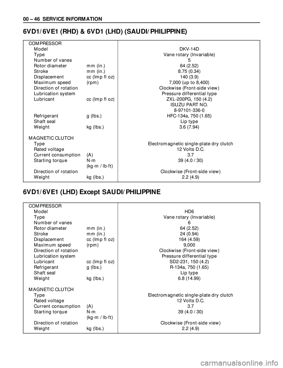
COMPRESSOR
Model DKV-14D
Type Vane rotary (Invariable)
Number of vanes 5
Rotor diameter mm (in.) 64 (2.52)
Stroke mm (in.) 8.75 (0.34)
Displacement cc (Imp fl oz) 140 (3.9)
Maximum speed (rpm) 7,000 (up to 8,400)
Direction of rotation Clockwise (Front-side view)
Lubrication system Pressure differential type
Lubricant cc (Imp fl oz) ZXL-200PG, 150 (4.2)
ISUZU PART NO.
8-97101-336-0
Refrigerant g (lbs.) HFC-134a, 750 (1.65)
Shaft seal Lip type
Weight kg (lbs.) 3.6 (7.94)
MAGNETIC CLUTCH
Type Electromagnetic single-plate dry clutch
Rated voltage 12 Volts D.C.
Current consumption (A) 3.7
Starting torque Nám 39 (4.0 / 30)
(kgám / lbáft)
Direction of rotation Clockwise (Front-side view)
Weight kg (lbs.) 2.2 (4.9)
6VD1/6VE1 (RHD) & 6VD1 (LHD) (SAUDI/PHILIPPINE)
6VD1/6VE1 (LHD) Except SAUDI/PHILIPPINE
COMPRESSOR
Model HD6
Type Vane rotary (Invariable)
Number of vanes 6
Rotor diameter mm (in.) 64 (2.52)
Stroke mm (in.) 24 (0.94)
Displacement cc (Imp fl oz) 164 (4.59)
Maximum speed (rpm) 9,000
Direction of rotation Clockwise (Front-side view)
Lubrication system Pressure differential type
Lubricant cc (Imp fl oz) SD2-231, 150 (4.2)
Refrigerant g (lbs.) R-134a, 750 (1.65)
Shaft seal Lip type
Weight kg (lbs.) 6.8 (14.99)
MAGNETIC CLUTCH
Type Electromagnetic single-plate dry clutch
Rated voltage 12 Volts D.C.
Current consumption (A) 3.7
Starting torque Nám 39 (4.0 / 30)
(kgám / lbáft)
Direction of rotation Clockwise (Front-side view)
Weight kg (lbs.) 2.2 (4.9)
Page 86 of 3573
SERVICE INFORMATION 00 Ð 47
4JG2/4JX1
COMPRESSOR
Model DKS-15CH
Type Swash plate type
Number of cylinder 6
Bore mm (in.) 36 (1.4)
Stroke mm (in.) 24 (0.94)
Displacement cc (Imp fl oz) 147 (4.1)
Maximum speed (rpm) 7,000 (up to 8,400)
Direction of rotation Clockwise (Front-side view)
Lubrication system Pressure differential type
Lubricant cc (Imp fl oz) ZXL-100PG, 150 (4.2)
ISUZU PART NO.
8-97101-338-0
Refrigerant g (lbs.) HFC-134a, 750 (1.65)
Shaft seal Lip type
Weight kg (lbs.) 4.1 (9.0)
MAGNETIC CLUTCH
Type Electromagnetic single-plate dry clutch
Rated voltage 12 Volts D.C.
Current consumption (A) 3.7
Starting torque Nám 49 (5.0 / 36)
(kgám / lbáft)
Direction of rotation Clockwise (Front-side view)
Weight kg (lbs.) 2.3 (5.1)
Page 89 of 3573
00 Ð 50 SERVICE INFORMATION
Legend
1. Clutch Driver
2. Rotor Bearing Retainer
3. Pulley Rotor and Bearing
Assembly
4. Clutch Coil Assembly
5. Connector
6. Shaft Seal Parts
7. Pump Assembly
8. High Pressure Relief Valve
9. Shipping Cap
10. Special 134a Suction Port
11. Special 134a Discharge Port
Caution
The operations described below are based
on bench overhaul with the compressor
removed from the vehicle, except as noted.
They have been prepared in order of
accessibility of the components. When a
compressor is removed from the vehicle for
servicing, the amount of PAG lubricant
remaining in the compressor should be
drained, measured and recorded. This PAG
lubricant should then be discarded and an
equal amount of new PAG lubricant added to
the compressor.
The service compressor is shipped without
PAG oil. When service procedures require,
use only Isuzu approved PAG oil.
HEATING, VENTILATION AND AIR CONDITIONING(HVAC)
1
2
3
4
5
68
97
10
11
871RW002
Page 90 of 3573
SERVICE INFORMATION 00 Ð 51
Metric Thread Size Information
Compressor to mounting bracket bolts(Front)
M10´1.5 Ð 6H
Compressor to mounting bracket bolts(Rear)
M8´1.25 Ð 6H
Suction-discharge port screw
M10´1.5 Ð 6H
Compressor shaft
M9´1.25 Ð 6H
Internal hub-clutch drive assembly
M22´1.5 Ð 6H
Page 93 of 3573
00 Ð 54 SERVICE INFORMATION
ILLUSTRATION PARTS NO. PARTS NAME
5-8840-2007-0
Drive plate holder
(J-7624)
5-8840-0122-0
Drive plate puller
(J-33944-A)
5-8840-0621-0
Forcing screw
(J-33944-4)
5-8840-0121-0
Pulley puller pilot
(J-33943)
5-8840-0111-0
Pulley puller
(J-8433)
5-8840-120-0
Shaft seal remover and installer
(J-33942)
5-8840-0368-0
Shaft seal guide
(J-34614)
5-8840-0118-0
Pulley installer
(J-33940)
5-8840-0007-0
Drive handle
(J-8092)
DKS-15CH TYPE
901RX056
Page 95 of 3573
00 Ð 56 SERVICE INFORMATION
901RW032
ILLUSTRATION TOOL NO. TOOL NAME
5-8840-2609-0
O-Ring Installer
(J-33011)
5-8840-0368-0
Shaft Seal Protector
(J-34614)
5-8840-2616-0
Pressure Testing Connector
(J-39893)
901RW026
901RW027
901RW032
Page 130 of 3573

1B Ð 4 AIR CONDITIONING
The refrigeration cycle includes the following four
processes as the refrigerant changes repeatedly
from liquid to gas and back to liquid while
circulating.
EVAPORATION
The refrigerant is changed from a liquid to a gas
inside the evaporator. The refrigerant mist that
enters the evaporator vaporizes readily. The liquid
refrigerant removes the required quantity of heat
(latent heat of vaporization) from the air around the
evaporator core cooling fins and rapidly vaporizes.
Removing the heat cools the air, which is then
radiated from the fins and lowers the temperature
of the air inside the vehicle.
The refrigerant liquid sent from the expansion valve
and the vaporized refrigerant gas are both present
inside the evaporator and the liquid is converted to
gas.
With this change from liquid to gas, the pressure
inside the evaporator must be kept low enough for
vaporization to occur at a lower temperature.
Because of that, the vaporized refrigerant is sucked
into the compressor.
COMPRESSION
The refrigerant is compressed by the compressor
until it is easily liquefied at normal temperature.
The vaporized refrigerant in the evaporator is
sucked into the compressor. This action maintains
the refrigerant inside the evaporator at a low
pressure so that it can easily vaporize, even at low
temperatures close to 0¡C (32¡F).
Also, the refrigerant sucked into the compressor is
compressed inside the cylinder to increase the
pressure and temperature to values such that the
refrigerant can easily liquefy at normal ambient
temperatures.
CONDENSATION
The refrigerant inside the condenser is cooled by
the outside air and changes from gas to liquid.
The high temperature, high pressure gas coming
from the compressor is cooled and liquefied by the
condenser with outside air and accumulated in the
receiver/drier. The heat radiated to the outside air
by the high temperature, high pressure gas in the
compressor is called heat of condensation. This is
the total quantity of heat (heat of vaporization) the
refrigerant removes from the vehicle interior via the
evaporator and the work (calculated as the quantity
of heat) performed for compression.
EXPANSION
The expansion valve lowers the pressure of the
refrigerant liquid so that it can easily vaporize.
The process of lowering the pressure to encourage
vaporization before the liquefied refrigerant is sent
to the evaporator is called expansion. In addition,
the expansion valve controls the flow rate of the
refrigerant liquid while decreasing the pressure.
That is, the quantity of refrigerant liquid vaporized
inside the evaporator is determined by the quantity
of heat which must be removed at a prescribed
vaporization temperature. It is important that the
quantity of refrigerant be controlled to exactly the
right value.
COMPRESSOR
The compressor performs two main functions:
It compresses low-pressure and low-temperature
refrigerant vapor from the evaporator into high-
pressure and high-temperature refrigerant vapor to
the condenser. And it pumps refrigerant and
refrigerant oil through the A/C system.
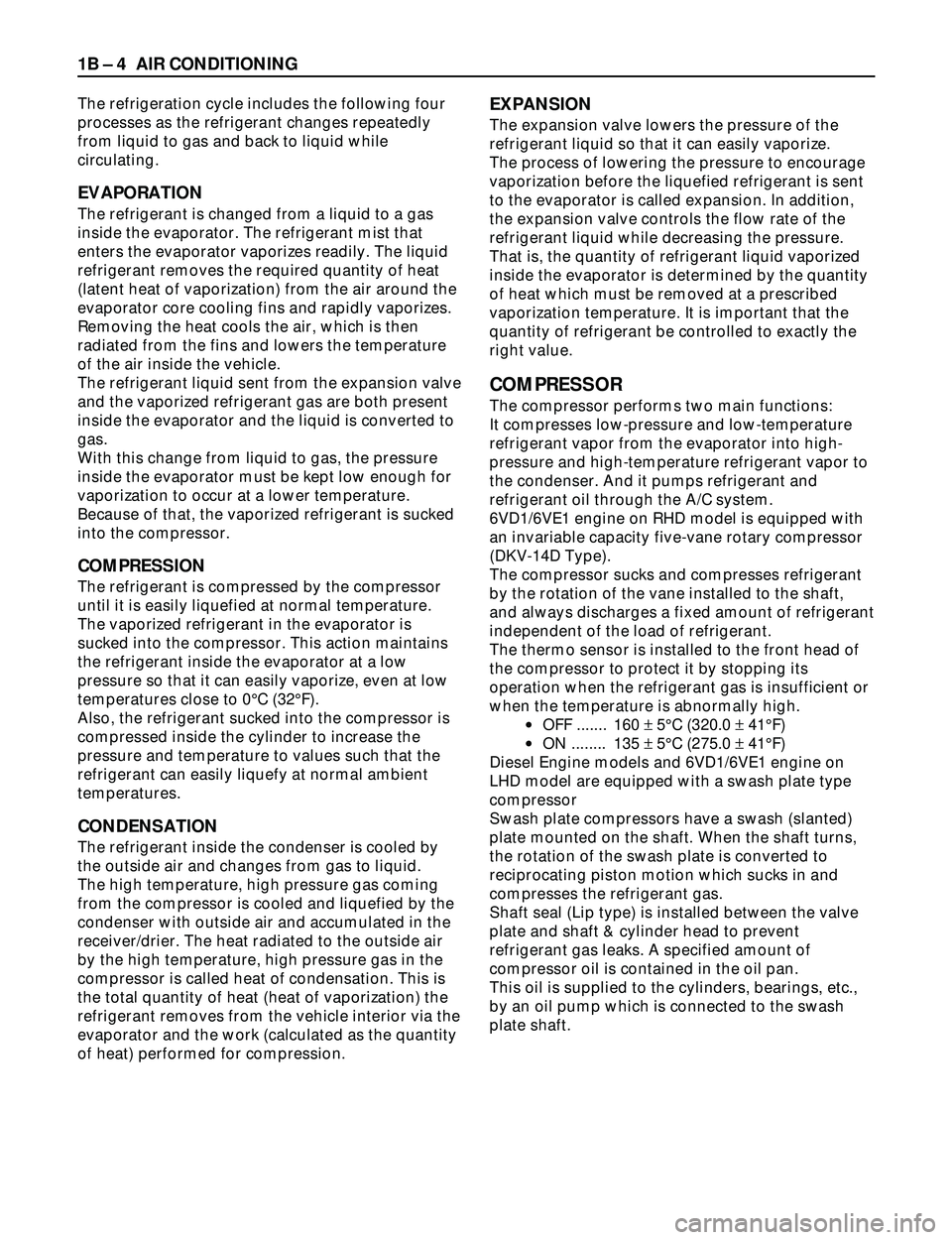
6VD1/6VE1 engine on RHD model is equipped with
an invariable capacity five-vane rotary compressor
(DKV-14D Type).
The compressor sucks and compresses refrigerant
by the rotation of the vane installed to the shaft,
and always discharges a fixed amount of refrigerant
independent of the load of refrigerant.
The thermo sensor is installed to the front head of
the compressor to protect it by stopping its
operation when the refrigerant gas is insufficient or
when the temperature is abnormally high.
·OFF ....... 160 ±5¡C (320.0 ±41¡F)
·ON ........ 135 ±5¡C (275.0 ±41¡F)
Diesel Engine models and 6VD1/6VE1 engine on
LHD model are equipped with a swash plate type
compressor
Swash plate compressors have a swash (slanted)
plate mounted on the shaft. When the shaft turns,
the rotation of the swash plate is converted to
reciprocating piston motion which sucks in and
compresses the refrigerant gas.
Shaft seal (Lip type) is installed between the valve
plate and shaft & cylinder head to prevent
refrigerant gas leaks. A specified amount of
compressor oil is contained in the oil pan.
This oil is supplied to the cylinders, bearings, etc.,
by an oil pump which is connected to the swash
plate shaft.