Page 3482 of 3573

SUPPLEMENTAL RESTRAINT SYSTEM9J±45
3. Disconnect the yellow 2±pin connector located
behind the air bag assembly and remove air bag
assembly.Refer to ªSRS Connectorsº in this section
for removal and installation.
827RT009
4. Disconnect horn lead connector.
5. Remove the steering wheel attachment nut.
6. Apply a setting mark across the steering wheel and
shaft so parts can be reassembled in their original
position.
430RS004
7. Move the tires to the straight ahead position before
removing the steering wheel and removing wheel with
5±8521±0016±0.
430RT009
8. Feed wiring though the wheel and remove wheel.
9. Remove the steering lower cover and engine hood
opening lever.
10. Remove the driver knee bolster assembly.
740RT015
11. Remove the steering column cover.
12. Remove air conditioning lower duct.
13. Disconnect the wiring harness connectors located at
the base of steering column.
CAUTION: Never apply force to the steering wheel
in direction of the shaft by using a hammer or other
impact tools in an attempt to remove the steering
wheel. The steering shaft is designed as an energy
absorbing unit.
14. Remove the combination switch assembly with SRS
coil.
Page 3483 of 3573
SUPPLEMENTAL RESTRAINT SYSTEM 9J±46
NOTE: S R S c o i l i s a p a r t o f combination switch
assembly, which cannot be replaced separately.
Therefore, be sure not to remove the SRS coil from the
combination switch assembly.
15. Remove the snap ring.
16. Remove the cushion rubber.
17. Disconnect shift lock cable (A/T only).
18. Disconnect the starter switch harness connector
located base of steering column.
19. Remove steering lock cylinder assembly.
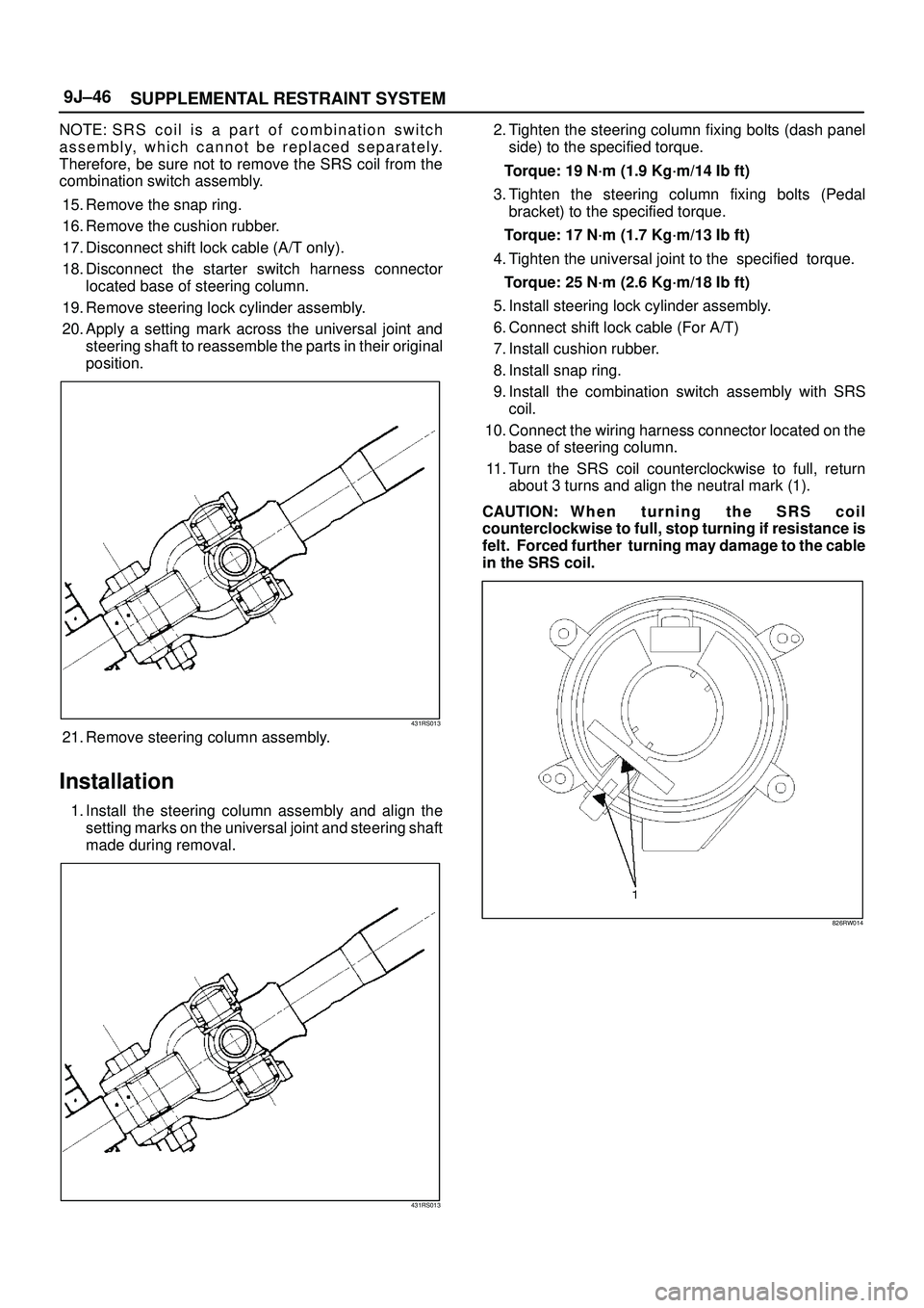
20. Apply a setting mark across the universal joint and
steering shaft to reassemble the parts in their original
position.
431RS013
21. Remove steering column assembly.
Installation
1. Install the steering column assembly and align the
setting marks on the universal joint and steering shaft
made during removal.
431RS013
2. Tighten the steering column fixing bolts (dash panel
side) to the specified torque.
Torque: 19 N´m (1.9 Kg´m/14 Ib ft)
3. Tighten the steering column fixing bolts (Pedal
bracket) to the specified torque.
Torque: 17 N´m (1.7 Kg´m/13 Ib ft)
4. Tighten the universal joint to the specified torque.
Torque: 25 N´m (2.6 Kg´m/18 Ib ft)
5. Install steering lock cylinder assembly.
6. Connect shift lock cable (For A/T)
7. Install cushion rubber.
8. Install snap ring.
9. Install the combination switch assembly with SRS
coil.
10. Connect the wiring harness connector located on the
base of steering column.
11. Turn the SRS coil counterclockwise to full, return
about 3 turns and align the neutral mark (1).
CAUTION: W h e n t u r n i n g t h e S R S c o i l
counterclockwise to full, stop turning if resistance is
felt. Forced further turning may damage to the cable
in the SRS coil.
826RW014
Page 3564 of 3573
PAGE BACK PAGE NEXT
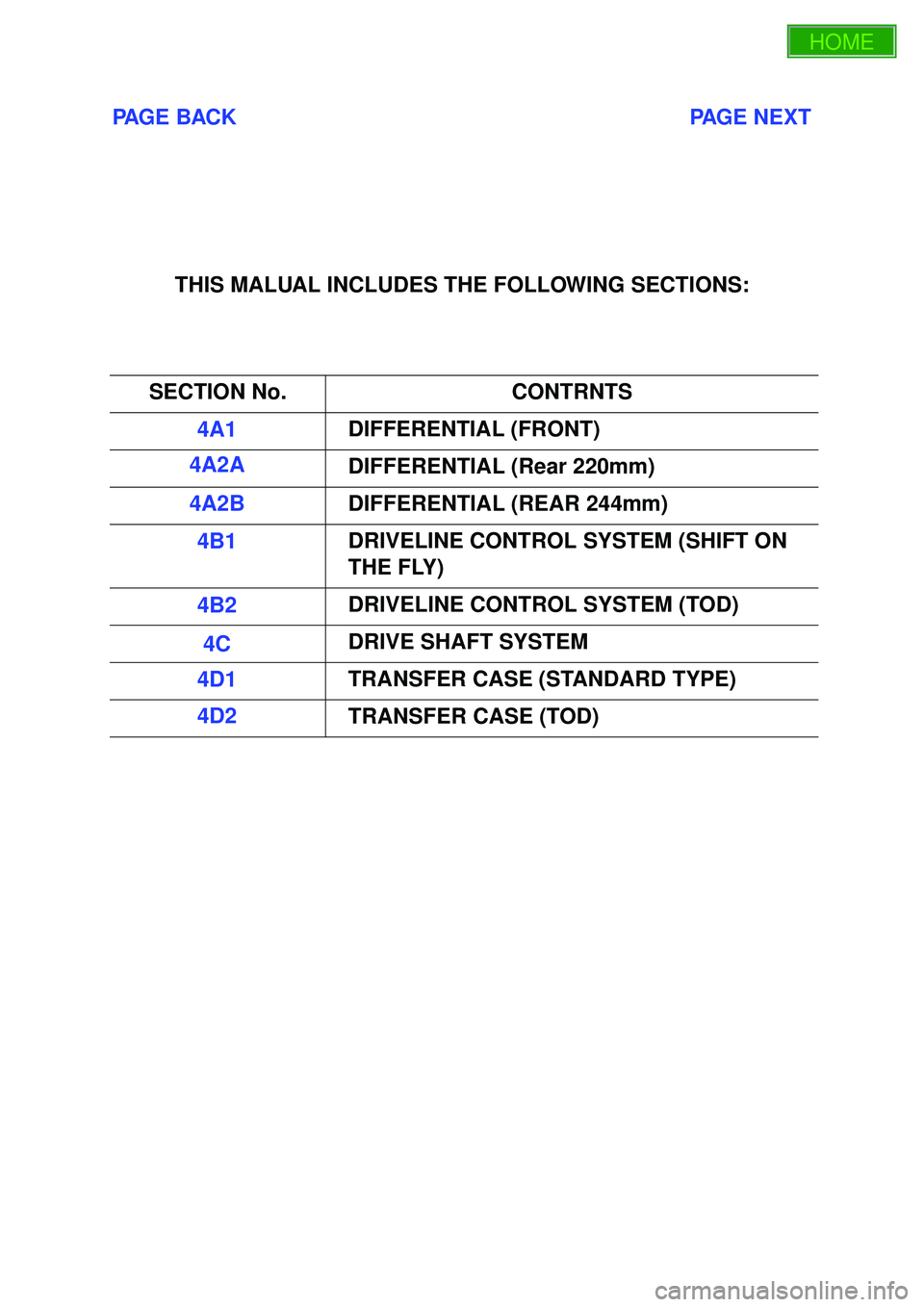
THIS MALUAL INCLUDES THE FOLLOWING SECTIONS:
SECTION No. CONTRNTS
4A1 DIFFERENTIAL (FRONT)
4A2A DIFFERENTIAL (Rear 220mm)
4A2B DIFFERENTIAL (REAR 244mm)
4B1 DRIVELINE CONTROL SYSTEM (SHIFT ON
THE FLY)
4B2 DRIVELINE CONTROL SYSTEM (TOD)
4C DRIVE SHAFT SYSTEM
4D1 TRANSFER CASE (STANDARD TYPE)
4D2 TRANSFER CASE (TOD)