ENTERTAINMENT8C–7
Radio
Removal
1. Disconnect the battery ground cable.
2. Remove the front console assembly (1).
Refer to the Instrument Panel Assembly in Body
Structure section.
3. Remove the lower cluster assembly (2).
Refer to the Instrument Panel Assembly in Body
Structure section.
4. Remove the instrument panel driver lower cover
assembly (3).
Refer to the Instrument Panel Assembly in Body
Structure section.
821RW024
5. Remove the instrument panel cluster assembly(4).
Refer to the Instrument Panel Assembly in Body
Structure section.
6. Remove two screws and disconnect the radio
connector(5) and antenna feeder plug(6) to remove
the radio(7).
825RW039
Installation
To install, follow the removal steps in the reverse order.
8D – 350 WIRING SYSTEM
Audio
General Description
The audio circuit is designed for the current to flow
through the receiver circuit when the radio switch is
turned on with the starter switch in“ACC” or “ON”.
Current runs through the memory circuit of the audio
regardless of the position of the starter switch.
The radio antenna operates in connection to the radio
switch. The antenna rod goes up when the switch is
ON and goes down to be stored in the fender with the
switch OFF. The antenna rod also goes down when
the starter switch is turned off with radio on.
8F±48BODY STRUCTURE
Instrument Panel Assembly
Parts Location
This illustration is based on RHD and W/SRS.
740RW123
Legend
(1) Front Defroster Grille
(2) Vent Duct Assembly
(3) Instrument Harness Assembly
(4) Side Defroster Grille
(5) Meter Assembly
(6) Instrument Panel Cluster Assembly
(7) Driver Knee Bolster Assembly (W/SRS)
(8) Instrument Panel Driver Lower Cover
Assembly
(9) Radio Assembly(10) Lower Cluster Assembly
(11) Front Console Assembly
(12) Glove Box
(13) Instrument Panel Passenger Lower Cover
Assembly
(14) Passenger Knee Bolster Reinforcement
Assembly
(15) Control Lever Assembly
(16) Passenger Inflator Module (W/SRS)
(17) Instrument Panel Assembly
8F±50BODY STRUCTURE
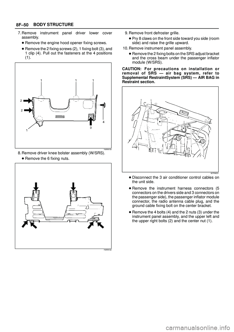
7. Remove instrument panel driver lower cover
assembly.
�Remove the engine hood opener fixing screws.
�Remove the 2 fixing screws (2), 1 fixing bolt (3), and
1 clip (4). Pull out the fasteners at the 4 positions
(1).
740RW105
8. Remove driver knee bolster assembly (W/SRS).
�Remove the 6 fixing nuts.
740RW122
9. Remove front defroster grille.
�Pry 8 claws on the front side toward you side (room
side) and raise the grille upward.
10. Remove instrument panel assembly.
�Remove the 2 fixing bolts on the SRS adjust bracket
and the cross beam under the passenger inflator
module (W/SRS).
CAUTION: F o r p recautions on installation or
removal of SRS Ð air bag system, refer to
Supplemental RestraintSystem (SRS) Ð AIR BAG in
Restraint section.
827RW031
�Disconnect the 3 air conditioner control cables on
the unit side.
�Remove the instrument harness connectors (5
connectors on the drivers side and 3 connectors on
the passenger side), the passenger inflator module
connector, the radio antenna cable plug, and the
ground cable fixing bolt on the center bracket.
�Remove the 4 bolts (4) and the 2 nuts (3) under the
instrument panel assembly, and the upper left and
the upper right bolts (2) and the center nut (1).
8F±52BODY STRUCTURE
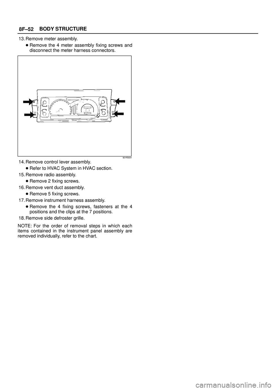
13. Remove meter assembly.
�Remove the 4 meter assembly fixing screws and
disconnect the meter harness connectors.
821RS034
14. Remove control lever assembly.
�Refer to HVAC System in HVAC section.
15. Remove radio assembly.
�Remove 2 fixing screws.
16. Remove vent duct assembly.
�Remove 5 fixing screws.
17. Remove instrument harness assembly.
�Remove the 4 fixing screws, fasteners at the 4
positions and the clips at the 7 positions.
18. Remove side defroster grille.
NOTE: For the order of removal steps in which each
items contained in the instrument panel assembly are
removed individually, refer to the chart.
8F±53 BODY STRUCTURE
Installation
To install, follow the removal steps in the reverse order.
Order Of Removal/Installation Steps For Each Item
Removal Item
Removal ProcedureRemoval Step
Front console assem-
blyShift knob (M/T), Power & Winter SW (A/T), Transfer knob, Seat
heater/Miller SW conn. and 4 screws1, 2
Lower cluster assem-
bly3 screws, Ciger lighter conn. and Ashtray illumination conn.1~3
Glove box2 screws4
Instrument panel pas-
senger lower cover7 screws and 1 clip1~5
Passenger knee bol-
ster reinforcement4 nuts and 4 bolts1~6
Instrument panel driver
lower coverEngine hood opening fixing screw, 2 screws, 1 bolt, 1 clip and fasten-
ers at 4 positions1~3, 7
Driver knee bolster6 nuts1~3, 7, 8
Front defroster grilleClaws at 8 positions9
Instrument panel as-
sembly2 bolts (SRS adjust bracket~ cross beam), A/C control cable (Unit
side at 3 position), Instrument harness connector (Driver side 5 posi-
tion, assist side 3 position), SRS module conn., Radio antenna jack,
Earth cable, 9 bolts and 3 nuts1~10
Passenger inflator
module4 nuts (SRS module~Instrument panel), 2 nuts 0 and 2 washers
(SRS module~support bracket) and 2 clips1~6, 11
Instrument panel clus-
ter5 Screws, fastener at 4 position and each SW conn.1~3, 7, 12
Meter assembly4 screws and connectors1~3, 7, 12, 13
A/C control panel as-
sembly4 screws and connectors1~3, 7, 12, 14
Radio assembly2 screws1~3, 15
Vent duct assembly5 screws1~10, 16
Instrument harness as-
sembly4 screws, fasteners at 4 position, and clips at 7 position1~10, 17
Side defroster grille18
M/T = Manual Transmission
A/T = Automatic Transmission
SRS = Supplemental Restraint System
A/C = Air Conditioning
.
Refer to the Instrument Panel Assembly in Body
Structure section.
3. Remove the lowe")

 Front Defroster Grille
(2) Vent Duct Assembly
(3) Instrument Harness Asse")