1998 ISUZU TROOPER differential
[x] Cancel search: differentialPage 131 of 3573
AIR CONDITIONING 1B Ð 5
With some compressors the differential between
the intake pressure and discharge pressure
generated while the compressor is operating is
used for lubrication instead of an oil pump.
The specified amount of the DKV-14D, DKS-15CH
and HD6 compressors oil is 150cc (4.2 Imp fl oz).
Also, compressor oil to be used varies according to
the compressor model. Be sure to avoid mixing
two or more different types of oil.
If the wrong oil is used, lubrication will be poor and
the compressor will seize or malfunction.
The magnetic clutch connector is a waterproof type.
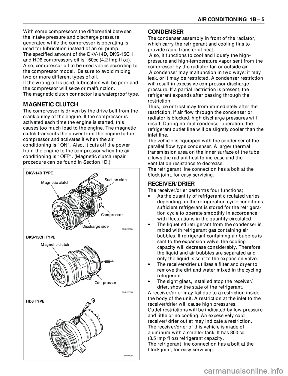
MAGNETIC CLUTCH
The compressor is driven by the drive belt from the
crank pulley of the engine. If the compressor is
activated each time the engine is started, this
causes too much load to the engine. The magnetic
clutch transmits the power from the engine to the
compressor and activates it when the air
conditioning is ÒONÓ. Also, it cuts off the power
from the engine to the compressor when the air
conditioning is ÒOFFÓ. (Magnetic clutch repair
procedure can be found in Section 1D.)
CONDENSER
The condenser assembly in front of the radiator,
which carry the refrigerant and cooling fins to
provide rapid transfer of heat.
Also, it functions to cool and liquefy the high-
pressure and high-temperature vapor sent from the
compressor by the radiator fan or outside air.
A condenser may malfunction in two ways: it may
leak, or it may be restricted. A condenser restriction
will result in excessive compressor discharge
pressure. If a partial restriction is present, the
refrigerant expands after passing through the
restriction.
Thus, ice or frost may from immediately after the
restriction. If air flow through the condenser or
radiator is blocked, high discharge pressures will
result. During normal condenser operation, the
refrigerant outlet line will be slightly cooler than the
inlet line.
The vehicle is equipped with the condenser of the
parallel flow type condenser. A larger thermal
transmission area on the inner surface of the tube
allows the radiant heat to increase and the
ventilation resistance to decrease.
The refrigerant line connection has a bolt at the
block joint, for easy servicing.
RECEIVER/DRIER
The receiver/drier performs four functions;
·As the quantity of refrigerant circulated varies
depending on the refrigeration cycle conditions,
sufficient refrigerant is stored for the refrigera-
tion cycle to operate smoothly in accordance
with fluctuations in the quantity circulated.
·The liquefied refrigerant from the condenser is
mixed with refrigerant gas containing air
bubbles. If refrigerant containing air bubbles is
sent to the expansion valve, the cooling
capacity will decrease considerably. Therefore,
the liquid and air bubbles are separated and
only the liquid is sent to the expansion valve.
·The receiver/drier utilizes a filter and dryer to
remove the dirt and water mixed in the cycling
refrigerant.
·The sight glass, installed atop the receiver/
drier, show the state of the refrigerant.
A receiver/drier may fail due to a restriction inside
the body of the unit. A restriction at the inlet to the
receiver/drier will cause high pressures.
Outlet restrictions will be indicated by low pressure
and little or no cooling. An excessively cold
receiver/ drier outlet may indicate a restriction.
The receiver/drier of this vehicle is made of
aluminum with a smaller tank. It has 300 cc
(8.5 Imp fl oz) refrigerant capacity.
The refrigerant line connection has a bolt at the
block joint, for easy servicing.
DKV-14D TYPE
DKS-15CH TYPE
HD6 TYPE
Magnetic clutch
CompressorSuction side
Discharge side
Compressor Magnetic clutch
852RW031 871RY00012
871RY00011
Page 259 of 3573
COMPRESSOR OVERHAUL 1D Ð 3
solvent, and dried with dry air. Use only lint free
cloths to wipe parts.
The operations described below are based on
bench overhaul with compressor removed from the
car, except as noted. They have been prepared in
order of accessibility of the components. When the
compressor is removed from the car for servicing,
the oil remaining in the compressor should be
discarded and new refrigerant oil added to the
compressor.
Magnetic clutch assembly repair procedures require
that the system be discharged of refrigerant. (Refer
to Section 1B for ÒREFRIGERANT RECOVERYÓ.)
Compressor malfunction will appear in one of four
ways: noise, seizure, leakage or low discharge
pressure. Resonant compressor noises are not
cause for alarm; however, irregular noise or rattles
may indicate broken parts or excessive clearances
due to wear. To check seizure, de-energize the
magnetic clutch and check to see if the drive plate
can be rotated. If rotation is impossible, the
compressor is seized. Low discharge pressure may
be due to a faulty internal seal of the compressor,
or a restriction in the compressor. Low discharge
pressure may also be due to an insufficient
refrigerant charge or a restriction elsewhere in the
system. These possibilities should be checked prior
to servicing the compressor. If the compressor is
inoperative, but is not seized, check to see if current
is being supplied to the magnetic clutch coil
terminals.
The compressor has vanes built into a rotor which
is mounted on a shaft.
When the shaft rotates, the vanes built into the
cylinder block assembly are opened by centrifugal
force.
This changes the volume of the space formed by
the rotor and cylinder, resulting in the intake and
compression of the refrigerant gas. The discharge
valve and the valve stopper, which protects the
discharge valve, are built into the cylinder block
assembly. There is no suction valve but a shaft seal
is installed between the shaft and head; a trigger
valve, which applies back pressure to the vanes, is
installed in the cylinder block and a refrigerant gas
temperature sensor is installed in the front head.
The specified quantity of compressor oil is
contained in the compressor to lubricate the various
parts using the refrigerant gas discharge pressure.
6VD1 engine is equipped with an invariable
capacity five-vane rotary compressor (DKV-14D
Type).
The compressor sucks and compresses refrigerant
by the rotation of the vane installed to the shaft,
and always discharges a fixed amount of refrigerant
independent of the load of refrigerant.The thermo sensor is installed to the front head of
the compressor to protect it by stopping its
operation when the refrigerant gas is insufficient or
when the temperature get abnormally high.
·OFF ..... 160 ±5¡C (320.0 ±9.0¡F)
·ON ..... 135 ±5¡C (275.0 ±9.0¡F)
4JG2 Engine are provided with a swash plate type
compressor (DKS-15CH Type)
Swash plate compressors have a swash (slanted)
plate mounted on the shaft. When the shaft turns,
the rotation of the swash plate is converted to
reciprocating piston motion which sucks in and
compresses the refrigerant gas.
Shaft seal (Lip type) is installed between the valve
plate and shaft & cylinder head to prevent
refrigerant gas leaks. A specified amount of
compressor oil is contained in the oil pan.
This oil is supplied to the cylinders, bearings, etc.,
by an oil pump which is connected to the swash
plate shaft.
With some compressors the differential between
the intake pressure and discharge pressure
generated while the compressor is operating is
used for lubrication instead of an oil pump.
Three pistons are arranged at 120g intervals around
the center of the swash plate shaft. These pistons
are connected to the ends of the swash plate
through shoe disks and balls.
The rotation of the swash plate causes
reciprocating movement of the piston inside the
cylinders, with each piston operating as two
cylinders. Because of that, the compressor operates
as though it has 6 cylinders.
The specified amount of the compressors oil is
150cc (4.2 Imp fl oz).
Also, compressor oil to be used varies according to
the compressor model. Be sure to avoid mixing two
or more different types of oil.
If the wrong oil is used, lubrication will be poor and
the compressor will seize or malfunction.
Page 438 of 3573
4A1±1 DIFFERENTIAL (FRONT)
DRIVELINE/AXLE
CONTENTS
Differential (Front) 4A1. . . . . . . . . . . . . . . . . . . . . . .
Differential (Rear/220mm) 4A2A. . . . . . . . . . . . . . . .
Differential (Rear/244mm) 4A2B. . . . . . . . . . . . . . . .
Driveline Control System (Shift on the Fly) 4B1. . Driveline Control System (TOD) 4B2. . . . . . . . . . .
Driveshaft System 4C. . . . . . . . . . . . . . . . . . . . . . .
Transfer Case (Standard Type) 4D1. . . . . . . . . . .
Transfer Case (TOD) 4D2. . . . . . . . . . . . . . . . . . . .
DIFFERENTIAL (FRONT)
CONTENTS
Service Precaution 4A1±1. . . . . . . . . . . . . . . . . . . . . .
Front Drive Axle 4A1±2. . . . . . . . . . . . . . . . . . . . . . . . .
Diagnosis 4A1±2. . . . . . . . . . . . . . . . . . . . . . . . . . . . .
Pinion Shaft Oil Seal 4A1±3. . . . . . . . . . . . . . . . . . . . .
Pinion Shaft Oil Seal and Associated Parts 4A1±3
Removal 4A1±3. . . . . . . . . . . . . . . . . . . . . . . . . . . . .
Inspection and Repair 4A1±4. . . . . . . . . . . . . . . . . .
Installation 4A1±4. . . . . . . . . . . . . . . . . . . . . . . . . . . .
Front Drive Axle Assembly 4A1±5. . . . . . . . . . . . . . .
Front Drive Axle Assembly and
Associated Parts 4A1±5. . . . . . . . . . . . . . . . . . . . . .
Removal 4A1±5. . . . . . . . . . . . . . . . . . . . . . . . . . . . . Installation 4A1±7. . . . . . . . . . . . . . . . . . . . . . . . . . . .
Differential Assembly 4A1±9. . . . . . . . . . . . . . . . . . . .
Disassembled View 4A1±9. . . . . . . . . . . . . . . . . . . .
Disassembly 4A1±9. . . . . . . . . . . . . . . . . . . . . . . . . .
Reassembly 4A1±12. . . . . . . . . . . . . . . . . . . . . . . . . .
Differential Cage Assembly 4A1±21. . . . . . . . . . . . . . .
Disassembled View 4A1±21. . . . . . . . . . . . . . . . . . . .
Disassembly 4A1±21. . . . . . . . . . . . . . . . . . . . . . . . . .
Inspection and Repair 4A1±22. . . . . . . . . . . . . . . . . .
Reassembly 4A1±23. . . . . . . . . . . . . . . . . . . . . . . . . .
Main Data and Specifications 4A1±25. . . . . . . . . . .
Special Tools 4A1±28. . . . . . . . . . . . . . . . . . . . . . . . . .
Service Precaution
WARNING: I F S O E Q U IPPED WITH A
SUPPLEMENTAL RESTRAINT SYSTEM (SRS),
REFER TO THE SRS COMPONENT AND WIRING
LOCATION VIEW IN ORDER TO DETERMINE
WHETHER YOU ARE PERFORMING SERVICE ON OR
NEAR THE SRS COMPONENTS OR THE SRS
WIRING. WHEN YOU ARE REFORMING SERVICE ON
OR NEAR THE SRS COMPONENTS OR THE SRS
WIRING, REFER TO THE SRS SERVICE
INFORMATION. FAILURE TO FOLLOW WARNINGS
COULD RESULT IN POSSIBLE AIR BAG
DEPLOYMENT, PERSONAL INJURY, OR
OTHERWISE UNNEEDED SRS SYSTEM REPAIRS.CAUTION: Always use the correct fastener in the
proper location. When you replace a fastener, use
ONLY the exact part number for that application.
ISUZU will call out those fasteners that require a
replacement after removal. ISUZU will also call out
the fasteners that require thread lockers or thread
sealant. UNLESS OTHERWISE SPECIFIED , do not
use supplemental coatings (Paints, greases, or other
corrosion inhibitors) on threaded fasteners or
fastener joint interfaces. Generally,such coatings
adversely affect the fastener torque and the joint
clamping force, and may damage the fastener. When
you install fasteners, use the correct tightening
sequence and specification. Following these
instructions can help you avoid damage to parts and
systems.
Page 439 of 3573
DIFFERENTIAL (FRONT) 4A1±2
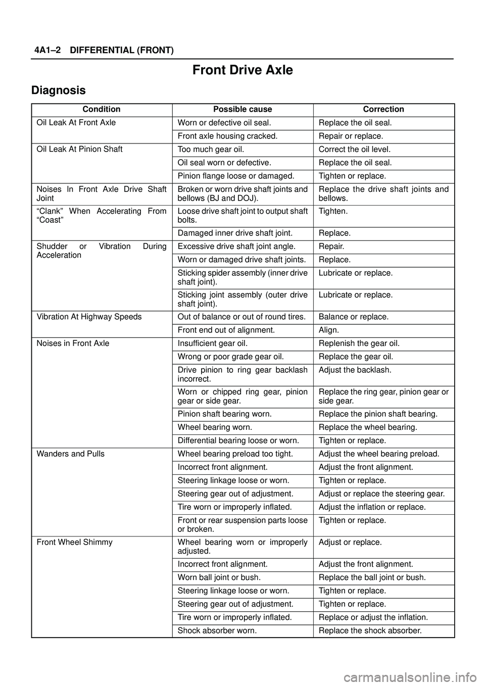
Front Drive Axle
Diagnosis
ConditionPossible causeCorrection
Oil Leak At Front AxleWorn or defective oil seal.Replace the oil seal.
Front axle housing cracked.Repair or replace.
Oil Leak At Pinion ShaftToo much gear oil.Correct the oil level.
Oil seal worn or defective.Replace the oil seal.
Pinion flange loose or damaged.Tighten or replace.
Noises In Front Axle Drive Shaft
JointBroken or worn drive shaft joints and
bellows (BJ and DOJ).Replace the drive shaft joints and
bellows.
ªClankº When Accelerating From
ªCoastºLoose drive shaft joint to output shaft
bolts.Tighten.
Damaged inner drive shaft joint.Replace.
Shudder or Vibration During
Acceleration
Excessive drive shaft joint angle.Repair.
AccelerationWorn or damaged drive shaft joints.Replace.
Sticking spider assembly (inner drive
shaft joint).Lubricate or replace.
Sticking joint assembly (outer drive
shaft joint).Lubricate or replace.
Vibration At Highway SpeedsOut of balance or out of round tires.Balance or replace.
Front end out of alignment.Align.
Noises in Front AxleInsufficient gear oil.Replenish the gear oil.
Wrong or poor grade gear oil.Replace the gear oil.
Drive pinion to ring gear backlash
incorrect.Adjust the backlash.
Worn or chipped ring gear, pinion
gear or side gear.Replace the ring gear, pinion gear or
side gear.
Pinion shaft bearing worn.Replace the pinion shaft bearing.
Wheel bearing worn.Replace the wheel bearing.
Differential bearing loose or worn.Tighten or replace.
Wanders and PullsWheel bearing preload too tight.Adjust the wheel bearing preload.
Incorrect front alignment.Adjust the front alignment.
Steering linkage loose or worn.Tighten or replace.
Steering gear out of adjustment.Adjust or replace the steering gear.
Tire worn or improperly inflated.Adjust the inflation or replace.
Front or rear suspension parts loose
or broken.Tighten or replace.
Front Wheel ShimmyWheel bearing worn or improperly
adjusted.Adjust or replace.
Incorrect front alignment.Adjust the front alignment.
Worn ball joint or bush.Replace the ball joint or bush.
Steering linkage loose or worn.Tighten or replace.
Steering gear out of adjustment.Tighten or replace.
Tire worn or improperly inflated.Replace or adjust the inflation.
Shock absorber worn.Replace the shock absorber.
Page 440 of 3573

4A1±3 DIFFERENTIAL (FRONT)
Pinion Shaft Oil Seal
Pinion Shaft Oil Seal and Associated Parts
415RW015
Legend
(1) Flange Nut
(2) Flange(3) Oil Seal
(4) Outer Bearing
(5) Collapsible Spacer
Removal
1. Raise the vehicle and support it at the frame.
The hoist must remain under the front axle housing.
2. Drain the front axle oil by loosening the drain plug(1).
412RS001
Page 441 of 3573
DIFFERENTIAL (FRONT) 4A1±4
3. Remove the front propeller shaft. Refer to Front
Propeller Shaft in this section.
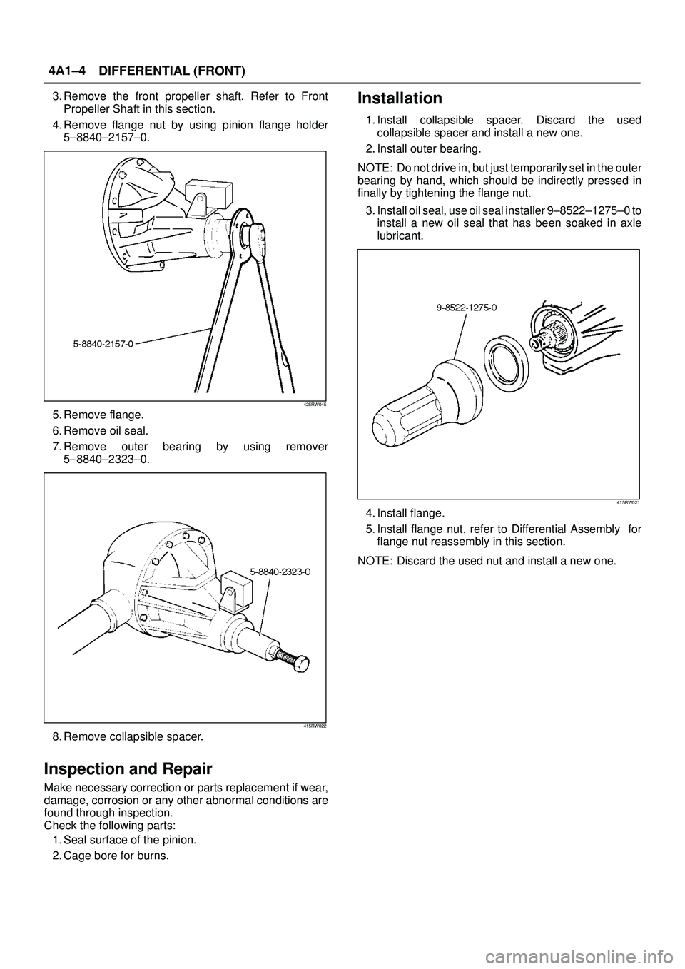
4. Remove flange nut by using pinion flange holder
5±8840±2157±0.
425RW045
5. Remove flange.
6. Remove oil seal.
7. Remove outer bearing by using remover
5±8840±2323±0.
415RW022
8. Remove collapsible spacer.
Inspection and Repair
Make necessary correction or parts replacement if wear,
damage, corrosion or any other abnormal conditions are
found through inspection.
Check the following parts:
1. Seal surface of the pinion.
2. Cage bore for burns.
Installation
1. Install collapsible spacer. Discard the used
collapsible spacer and install a new one.
2. Install outer bearing.
NOTE: Do not drive in, but just temporarily set in the outer
bearing by hand, which should be indirectly pressed in
finally by tightening the flange nut.
3. Install oil seal, use oil seal installer 9±8522±1275±0 to
install a new oil seal that has been soaked in axle
lubricant.
415RW021
4. Install flange.
5. Install flange nut, refer to Differential Assembly for
flange nut reassembly in this section.
NOTE: Discard the used nut and install a new one.
Page 442 of 3573
4A1±5 DIFFERENTIAL (FRONT)
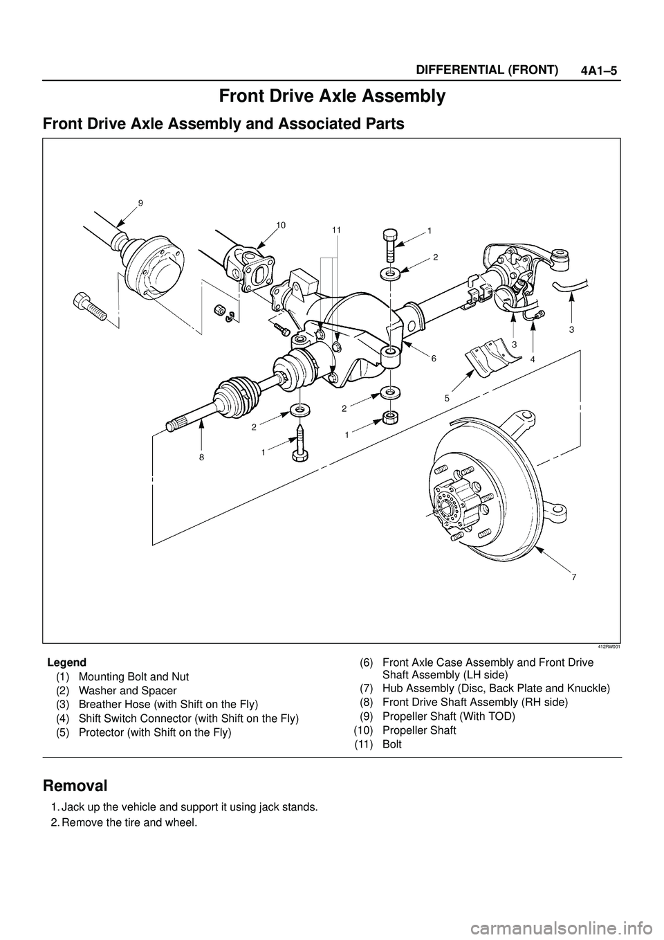
Front Drive Axle Assembly
Front Drive Axle Assembly and Associated Parts
412RW001
Legend
(1) Mounting Bolt and Nut
(2) Washer and Spacer
(3) Breather Hose (with Shift on the Fly)
(4) Shift Switch Connector (with Shift on the Fly)
(5) Protector (with Shift on the Fly)(6) Front Axle Case Assembly and Front Drive
Shaft Assembly (LH side)
(7) Hub Assembly (Disc, Back Plate and Knuckle)
(8) Front Drive Shaft Assembly (RH side)
(9) Propeller Shaft (With TOD)
(10) Propeller Shaft
(11) Bolt
Removal
1. Jack up the vehicle and support it using jack stands.
2. Remove the tire and wheel.
Page 443 of 3573
DIFFERENTIAL (FRONT) 4A1±6
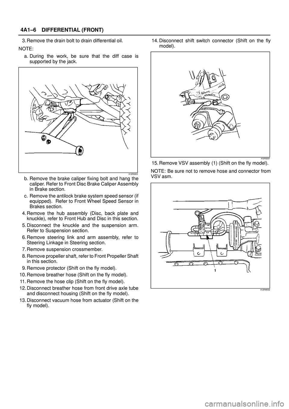
3. Remove the drain bolt to drain differential oil.
NOTE:
a. During the work, be sure that the diff case is
supported by the jack.
412RS003
b. Remove the brake caliper fixing bolt and hang the
caliper. Refer to Front Disc Brake Caliper Assembly
in Brake section.
c. Remove the antilock brake system speed sensor (if
equipped). Refer to Front Wheel Speed Sensor in
Brakes section.
4. Remove the hub assembly (Disc, back plate and
knuckle), refer to Front Hub and Disc in this section.
5. Disconnect the knuckle and the suspension arm.
Refer to Suspension section.
6. Remove steering link and arm assembly, refer to
Steering Linkage in Steering section.
7. Remove suspension crossmember.
8. Remove propeller shaft, refer to Front Propeller Shaft
in this section.
9. Remove protector (Shift on the fly model).
10. Remove breather hose (Shift on the fly model).
11. Remove the hose clip (Shift on the fly model).
12. Disconnect breather hose from front drive axle tube
and disconnect housing (Shift on the fly model).
13. Disconnect vacuum hose from actuator (Shift on the
fly model).14. Disconnect shift switch connector (Shift on the fly
model).
412RS031
15. Remove VSV assembly (1) (Shift on the fly model).
NOTE: Be sure not to remove hose and connector from
VSV asm.
412RW002