Page 2121 of 3573

6E±228
4JX1±TC ENGINE DRIVEABILITY AND EMISSIONS
General Description (Air Induction)
Air Induction System
The air induction system filters contaminants from the
outside air, and directs the progress of the air as it is
drawn into the engine. A remote-mounted air cleaner
prevents dirt and debris in the air from entering the
engine. The air duct assembly routes filtered air to the
throttle body. Air enters the engine by to following steps:
1. Through the throttle body.
2. Into the intake manifold.
3. Through the cylinder head intake ports.
4. Into the cylinders.
General Description (Fuel Metering)
Deceleration Mode
The ECM reduces the amount of fuel injected when it
detects a decrease in the Accelerator position.
Fuel Injector
Fuel injector comprises the solenoid, hydraulic line, and
fuel line. Fuel injection is controlled by the continuity time
signal and continuity start timing signal from ECM to the
solenoid
ECM determines the running conditions of engine by
input signals such as engine speed. Accelerator throttle
valve opening, and engine coolant temperature, thereby
to send the solenoid the best suited signal to the engine
status. When current is carried to the solenoid, the
armature opens the poppet valve to alow high pressure oil
to run into the injector. Under the pressure of the oil, the
piston and plunger are depressed to compress the fuel in
the combustion chamber of the plunger. Specifically, the
pressure of the fuel compressed is increased by a piston
top/ plunger bottom area ratio over the pressure of high
pressure oil, thereby lifting the fuel nozzle end needle for
injecting fuel.
Fuel Metering System Components
The fuel metering system is made up of the following
parts:
�The fuel injectors.
�The intake throttle body.
�The Accelerator position (AP) sensor
�The ECM.
�The crankshaft position (CKP) sensor.
�The camshaft position (CMP) sensor.
Basic System Operation
Fuel is supplied through fuel filter to the fuel pump.
The fuel pump is installed to the oil pump, and fuel is
forced, through the fuel pump outlet, pipe and cylinder
head inside, into the fuel injector.
An orifice is provided at the rear fuel outlet of cylinder
head to control the pressure of oil.The injector is controlled by ECM which gives
opening/closing commands to the solenoid installed on
the top of the injector. Opening/closing operation of the
pressurized engine oil circuit of the injector controls fuel
injection quantity, fuel injection timing, etc.
A/C Clutch Diagnosis
A/C Request Signal
This signal tells the ECM when the A/C mode is selected
at the A/C control head. The ECM uses this to adjust the
idle speed.
Refer to
A/C Clutch Circuit Diagnosis for A/C wiring
diagrams and diagnosis for A/C electrical system.
General Description Exhaust Gas
Recirculation (EGR) System
EGR Purpose
The exhaust gas recirculation (EGR) system is use to
reduce emission levels of oxides of nitrogen (NOx). NOx
emission levels are caused by a high combustion
temperature. The EGR system lowers the NOx emission
levels by decreasing the combustion temperature.
The ECM uses information from the following sensors to
control EGR valve boost pressure.
�ECT
�ITP
�Engine Speed
�AP sensor
Page 2134 of 3573

ENGINE LUBRICATION 6G – 3
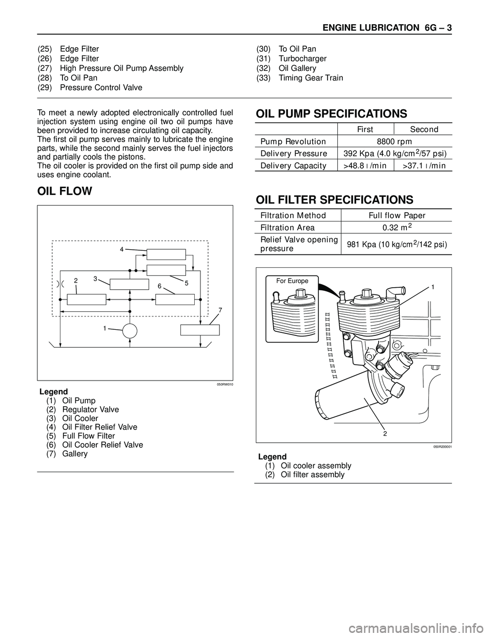
To meet a newly adopted electronically controlled fuel
injection system using engine oil two oil pumps have
been provided to increase circulating oil capacity.
The first oil pump serves mainly to lubricate the engine
parts, while the second mainly serves the fuel injectors
and partially cools the pistons.
The oil cooler is provided on the first oil pump side and
uses engine coolant.
OIL FLOW
Legend
(1) Oil Pump
(2) Regulator Valve
(3) Oil Cooler
(4) Oil Filter Relief Valve
(5) Full Flow Filter
(6) Oil Cooler Relief Valve
(7) Gallery
OIL PUMP SPECIFICATIONS
First Second
Pump Revolution 8800 rpm
Delivery Pressure 392 Kpa (4.0 kg/cm
2/57 psi)
Delivery Capacity >48.8 l/min >37.1 l/min
OIL FILTER SPECIFICATIONS
Filtration Method Full flow Paper
Filtration Area 0.32 m
2
Relief Valve opening 981 Kpa (10 kg/cm2/142 psi)pressure
Legend
(1) Oil cooler assembly
(2) Oil filter assembly (25) Edge Filter
(26) Edge Filter
(27) High Pressure Oil Pump Assembly
(28) To Oil Pan
(29) Pressure Control Valve(30) To Oil Pan
(31) Turbocharger
(32) Oil Gallery
(33) Timing Gear Train
17 65 4
3
2
050RW010
For Europe1
2
050R200001
Page 2630 of 3573

WIRING SYSTEM 8DÐ37
(4JG2 RHD)
Connector No. Cable harness Location Parts (Load)
B-1
Door mirror defogger (LH), FRT power window
& door lock SW-LH, Fan SW, FRT door key SW-
LH, FRT door lock actuator-LH, FRT door lock
SW-LH
B-2Sun roof SW, Sun roof control unit, Safety SW,
Limit SW
Body-LH
B-18
FRT door key SW-RH, FRT door lock & power
window SW-RH, FRT door lock actuator & lock
SW-RH, Door lock SW-RH, Door mirror
defogger (RH), RR wiper intermittent relay,
Starter relay
B-19
B-26Mirror control SW, Mirror folding SW, Mirror
defogger SW, Car telephone, Seat heater, Seat
heater SW, RR door lock actuator-LH, EBCM Body-RH Body harness
Body-center
C-16
4WD SW, Fuel filter SW2
C-16
VSV;FRT axle, FRT axle SW3
C-16
FRT fog light 4
C-16QOS-III control unit, Headlight wiper timer,
VSV;FICD, QOS/EGR control unit, Data link
connector7
C-16
Side turn signal light (LH)
8Fender-LH Engine room
harnessHeadlight wiper SW, Dimmer·passing SW,
Illumination controller, RR defogger SW,
Flasher unit, Power window relay, Lighting SW,
Glove box illumination light, Ashtray
illumination light, Clock, FRT fog light SW,
Variable intermittent (FRT wiper & washer SW),
Cigar lighter, Vehicle speed sensor (Meter),
Heater & A/C relay, Turn signal indicator light,
Anti-theft controller, RR power window SW-RH
C-16
5
Headlight wiper motor
C-16Clearance light, FRT turn signal light1B-28
RR power window SW-RH, EBCM, RR door lock
actuator-RH, Tilt motor & SW, Power seat SW,
Recliner motor & SW
Page 2632 of 3573

WIRING SYSTEM 8DÐ39
(4JG2 LHD)
Connector No. Cable harness Location Parts (Load)
B-1
Door mirror defogger (RH), FRT door lock key
SW-RH, FRT door lock actuator-RH, Door lock
SW-RH, FRT power window & door lock SW-
RH, Key & light remind buzzer (Saudi Arabia),
Sun roof SW, Sun roof control unit, Safety SW,
Limit SW
B-2Seat belt warning light (Saudi Arabia), Fan SW,
Turn signal indicator light, Vehicle speed
sensor (Meter), RR defogger SW, Clock, Cigar
lighter, Glove box illumination light, Ashtray
illumination light
Body-RH
B-18
FRT door lock key SW-LH, FRT door lock
actuator & lock SW-LH, Door lock SW-LH, FRT
door lock & power window SW-LH, Door
mirror defogger (LH), RR wiper intermittent
relay, Starter relay, Power window relay
B-19
B-26Mirror control SW, Mirror folding SW, Mirror
defogger SW, RR power window SW-RH, Car
telephone, RR door lock actuator-RH, Seat
heater, Seat heater SW, EBCM Body-LH Body harness
Body-center
C-16
4WD SW, Fuel filter SW2
C-16
VSV;FRT axle, FRT axle SW, Brake fluid SW3
C-16
FRT fog light 4
C-16VSV; FICD7
C-16
Data link connector, Side turn signal light (LH),
QOS-III control unit 8Fender-LH Engine room
harnessDimmer·passing SW, Illumination controller,
RR defogger SW, Flasher unit, Lighting SW,
Headlight wiper SW, FRT fog light SW, Variable
intermittent (FRT wiper & washer SW), Heater
& A/C relay, Anti-theft controller
C-16
5
Headlight wiper motor
C-16Clearance light, FRT turn signal light1B-28
Seat belt SW (Saudi Arabia), EBCM, Tilt motor
& SW, Power seat SW, Recliner motor & SW
Page 3018 of 3573
WIRING SYSTEM 8D – 425
Circuit Diagram (RHD 4JG2)-3
D08RW737
KMJ
H
L
BRAKE EHCU:ELECTRONIC HYDRAULIC CONTROL UNIT
SEDIMENTER 4WDBRAKE
FLUID
SWPARKING
BRAKE
SW
18
19
4WD
CONTROL
UNIT(19)
FRT AXLE
SW(2)
4WD
SW(1)0.5
LG
0.5
LG 0.5
LG 0.5
LGI-9
H-2723
7
2 0.5
V
0.3
V0.5
B/P
0.85
B/P
0.5
B0.5
B/P0.5
B/P I-9
H-9
H-674
1
8 9
213
1
FENDER-RH0.5
B/PI-9
H-16
C-15
C-39 C-15
FUEL
FILTER
SW
0.5
B1
2
FENDER-L HC-16 C-67
VACUUM
SW
1
C-68H-26
B-27
METER
Page 3032 of 3573
WIRING SYSTEM 8D – 439
Circuit Diagram (LHD 4JG2)-3
D08RW914
HSEAT
BELT
SW
BODY-LHB-18
BODY-CTR
BODY-RH
B-2
2
11 0.3
L
0.5
L
2.0
B 2.0
B 2.0
B 0.5
BI-9
B-24 H-25
1
B-24
SEAT
BELT
B-262
KMJL
BRAKE EHCU:ELECTRONIC HYDRAULIC CONTROL UNIT
SEDIMENTER 4WDBRAKE
FLUID
SWPARKING
BRAKE
SW
18
22
4WD
CONTROL
UNIT(19)
FRT AXLE
SW(2)
4WD
SW(1) SDM
(20)0.5
LG
0.5
LG 0.5
LG 0.85
LGI-9
H-2523
20
2 0.5
V
0.3
V0.5
B/P
0.85
B/P
0.5
B0.5
B/P0.5
B/P I-9
H-9
H-674
1
3 17
215
1
FENDER-LH0.5
B/PI-9
H-9
C-15
C-16 C-15
FUEL
FILTER
SW
0.5
B1
2
FENDER-L HC-16 C-67
VACUUM
SW
1
C-68H-25
B-27
METER
Page 3383 of 3573
8J±4EXTERIOR/INTERIOR TRIM
Consoles
Consoles and Associated Parts
This illustration is based on RHD
745RW009
Legend
(1) Shift Knob (M/T) / Transfer Knob (A/T)
(2) Assist Grip
(3) Fuel Filler Lid Opener(4) Center Console Assembly
(5) Front Seat Assembly (RH)
(6) Front Console Assembly
Removal
1. Disconnect the battery ground cable.
2. Remove the shift knob (M/T) / transfer knob (A/T).
3. Remove the front console assembly.
�Remove four fixing screws and disconnect the
switch connectors.
4. Remove the front seat assembly(RH).
�Refer to the Front Seat Assembly removal steps in
Seats section.
5. Remove the assist grip.
�Remove three bolts.
6. Remove the fuel filler lid opener.
�Remove the fuel filter lid opener(1) and disconnect
the cable(2).
686RW007