Page 1671 of 3573
FUEL SYSTEM 6C Ð 5
FUEL FILTER AND WATER SEPARATOR
A cartridge type fuel filter and a water separator are used along with the VE type injection pump.
As the inside of the injection pump is lubricated by the fuel which it is pumping, the fuel must be perfectly
clean. The fuel filter and the water separator remove water particles and other foreign material from the
fuel before it reaches the injection pump.
The water separator has an internal float. When the float reaches the specified level, a warning light comes
on to remind you to drain the water from the water separator.
A diaphragm type priming pump is installed at the top of the water separator. It is used during the water
draining and the air bleeding procedures.
Page 1673 of 3573
FUEL SYSTEM 6C Ð 7
ON-VEHICLE SERVICE
FUEL FILTER ASSEMBLY
REMOVAL
Preparation: Disconnect battery ground cable.
1. Fuel Filler Cap
2. Lead Switch Harness Connecter
3. Fuel Hose
·Disconnect fuel hose from filter body.
Plug the hose ends to prevent fuel spillage.
4. Remove the Bolt on Fuel Filter Bracket.
5. Fuel Filter Assembly
INSTALLATION
5. Fuel Filter Assembly
·Install the filter
4. Tighten the Fuel Filter Bracket Fixing Bolt.
3. Fuel Hose
·Connect hoses to filter body.
2. Lead Switch Harness Connecter
1. Fuel Filler Cap
·Connect the battery ground cable.
·Feed fuel to the injection pump by weans of the
priming, and bleed the fuel system.
Page 1674 of 3573

6C Ð 8 FUEL SYSTEM
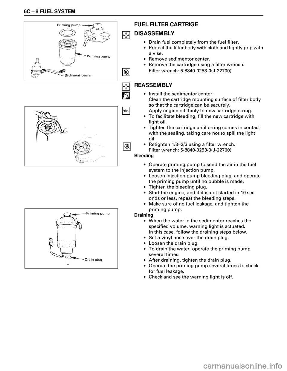
FUEL FILTER CARTRIGE
DISASSEMBLY
·Drain fuel completely from the fuel filter.
·Protect the filter body with cloth and lightly grip with
a vise.
·Remove sedimentor center.
·Remove the cartridge using a filter wrench.
Filter wrench: 5-8840-0253-0(J-22700)
REASSEMBLY
·Install the sedimentor center.
Clean the cartridge mounting surface of filter body
so that the cartridge can be securely.
Apply engine oil thinly to new cartridge o-ring.
·To facilitate bleeding, fill the new cartridge with
light oil.
·Tighten the cartridge until o-ring comes in contact
with the sealing, taking care not to spill the light
oil.
·Retighten 1/3~2/3 using a filter wrench.
Filter wrench: 5-8840-0253-0(J-22700)
Bleeding
·Operate priming pump to send the air in the fuel
system to the injection pump.
·Loosen injection pump bleeding plug, and operate
the priming pump until no bubble is made.
·Tighten the bleeding plug.
·Start the engine, and if it is not started in 10 sec-
onds or less, repeat the bleeding steps.
·Make sure of no fuel leakage, and tighten the
priming pump.
Draining
·When the water in the sedimentor reaches the
specified volume, warning light is actuated.
In this case, follow the draining steps below.
·Set a vinyI hose over the drain plug.
·Loosen the drain plug.
·To drain the water, operate the priming pump
several times.
·After draining, tighten the drain plug.
·Operate the priming pump several times to check
for fuel leakage.
·Check and see the warning light is off.
Page 1680 of 3573
6C Ð 14 FUEL SYSTEM
INJECTION PUMP ASSEMBLY
Removal Steps
1. Air cleaner cover & air duct
2. Intercooler assembly
3. Radiator assembly
4. Cooling fan assembly
5. P/S pump drive belt
6. AC generator drive belt7. Timing gear
8. Fuel filter assembly
9. Injection pump harness
10. Fuel hose and CSD hose
11. Injection pump Control cable
12. Injection pipe
13. Injection pump assembly
Installation Steps
To install, follow the removal steps in
the reverse order.
Page 1681 of 3573

FUEL SYSTEM 6C Ð 15
REMOVAL
Preparation:
·Disconnect battery ground cable.
·Drain coolant.
1. Air Cleaner Cover & Air Duct
2. Intercooler Assembly (4JG2-T ONLY)
· Refer to Intercooler Assembly removal.
3. Radiator Assembly
·Disconnect upper and lower hoses on the engine
side.
4. Cooling Fan Assembly
·Remove cooling fan asm and remove fan pulley
and spacer.
5. P/S Pump Drive Belt
·Loosen P/S pump lock bolt and adjust bolt remove
two drive belts.
6. AC Generator Drive Belt
·Loosen AC generator mounting bolt (under side)
and adjust, bolt and remove drive belt.
7. Timing Gear
·Refer to Timing Gear Removal
·Remove the loosened nut and fixing bolt and
remove the timing gear.
8.Fuel Filter Assembly
9. Injection Pump Harness
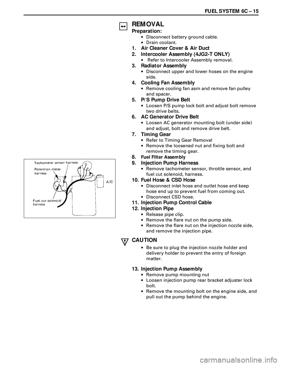
·Remove tachometer sensor, throttle sensor, and
fuel cut solenoid, harness.
10. Fuel Hose & CSD Hose
·Disconnect inlet hose and outlet hose and keep
hose end up to prevent fuel from coming out.
·Disconnect CSD hose.
11. Injection Pump Control Cable
12. Injection Pipe
·Release pipe clip.
·Remove the flare nut on the pump side.
·Remove the flare nut on the injection nozzle side,
and remove the injection pipe.
CAUTION
·Be sure to plug the injection nozzle holder and
delivery holder to prevent the entry of foreign
matter.
13. Injection Pump Assembly
·Remove pump mounting nut
·Loosen injection pump rear bracket adjuster lock
bolt.
·Remove the mounting bolt on the engine side, and
pull out the pump behind the engine.
Page 1682 of 3573

6C Ð 16 FUEL SYSTEM
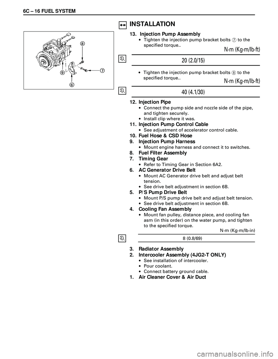
20 (2.0/15)N·m (Kg·m/lb·ft)
·Tighten the injection pump bracket bolts 8 to the
specified torque..
40 (4.1/30)N·m (Kg·m/lb·ft)
12. Injection Pipe
·Connect the pump side and nozzle side of the pipe,
and tighten securely.
·Install clip where it was.
11. Injection Pump Control Cable
·See adjustment of accelerator control cable.
10. Fuel Hose & CSD Hose
9. Injection Pump Harness
·Mount engine harness and connect it to switches.
8. Fuel Filter Assembly
7. Timing Gear
·Refer to Timing Gear in Section 6A2.
6. AC Generator Drive Belt
·Mount AC Generator drive belt and adjust belt
tension.
·See drive belt adjustment in section 6B.
5. P/S Pump Drive Belt
·Mount P/S pump drive belt and adjust belt tension.
·See drive belt adjustment in section 6B.
4. Cooling Fan Assembly
·Mount fan pulley, distance piece, and cooling fan
asm (in this order) on the water pump, and tighten
to the specified torque.
3. Radiator Assembly
2. Intercooler Assembly (4JG2-T ONLY)
·See installation of intercooler.
·Pour coolant.
·Connect battery ground cable.
1. Air Cleaner Cover & Air Duct
INSTALLATION
13. Injection Pump Assembly
·Tighten the injection pump bracket bolts 7 to the
specified torque..
8 (0.8/69)N·m (Kg·m/lb·in)
Page 1690 of 3573
6C Ð 24 FUEL SYSTEM
AIR CLEANER
REMOVAL
·Disconnect the hose coming.
1. Air Cleaner Cover
·Disconnect air hose.
2. Element
INSPECTION
Check the element for damage or clogging by dust.
Replace if it is damaged, or clean if it is clogged.
Cleaning Method
Top the element carefully not to damage the paper filter,
or clean the element by blowing with compressed air of
about 49kPa (0.5 kg/cm
2/71 psi)
from the clean side if it is
extremely dirty.
INSTALLATION
2. Element
1. Air Cleaner Cover
·Set the cover to the body completely, then clamp it
with the clip.
Page 1736 of 3573

ENGINE MECHANICAL 6A – 3
SERVICE INFORMATION
MAIN DATA AND SPECIFICATION
Engine type Diesel, four cycle water cooled inline
Camshaft type DOHC
Number of cylinders 4
Bore x stroke (mm) 95.4 x 104.9
Total piston displacement (cc) 2999
Compression ratio (to 1) 19.0
For Europe : 18.5
Engine weight (dry) N (kg/lb) 2492 (254/560) (A/T)
For Europe : 2422 (247/545) (A/T)
2649 (270/593) (M/T)
For Europe : 2697 (275/606) (M/T)
Engine idling speed (Reference) RPM 720
Compression pressure kpa (kg/cm
2/psi)-rpm 3040 (31/441)-200
Firing order 1–3–4–2
VALVE SYSTEM
Intake valves open at: B.T.D.C. 3°
close at: A.B.D.C. 57.6°
Exhaust valves open at: B.B.D.C. 56.5°
close at: A.T.D.C. 5°
Valve clearance (at cold) mm (in)
intake: 0.15 (0.006)
exhaust: 0.25 (0.01)
Oil filter Full flow and bypass combined type
Oil capacity (Original factory fill or rebuilt engine) 9.0 liters (7.9 US quarts)
Oil capacity (Service change)
with filter change 6.0 liters (6.3 US quarts)
without filter change 5.0 liters (5.3 US quarts)
Oil cooler Water cooled type
Inter cooler Air cooled type
Turbocharger method
Control method Wastegate control
Lubrication Pressurized control
Cooling method Coolant cooled
Crankshaft
As tufftriding (Nitrizing treatment) is applied to increase
crankshaft strength, crankpins and journals should not
be reground.
Piston Cooling
An oiling jet device for piston cooling is provided in the
lubricating oil circuit from the cylinder block oil gallery
via a check valve.
Take care not to damage any oiling jet when removing
and installing piston and connecting assembly.
Fuel Injection System
The injection system is oil rail type.
Quick On Start 4 System
QOS4 preheating system which features a quick-on
glow plug with thermometer control of the glowing time
and the afterglow time function, is applied.