Page 1126 of 1681
1
I
PowerRelays
RelayTest
JNOTE: See page 23-194 for turn signal/hazard relay
input test.
Normally.open type:
fWC2i
1. Check for continuitv between the terminals.
. There should be continuity between the A and B
terminals when power and ground are connect-
ed to the C and D terminals.
. There should be no continuity between the A
and B terminals when power is disconnected.
<2
F;Z
,,A
/ l'El--E \
ey
Normally-opon type:
'1. Check continuity between relay terminals.
. There should be continuity between the A and C
terminals when power and ground are connect-
ed to the B and D terminals.
o There should be no continuitv when oower is
disconnacted,
o Power window relay
. Radiator fan relay
. Condenser fan relay
. AVC compressor clutch relay
Typel:
c
I Blower motor relay
. Rear window defogger relay
Typel:
Terminal
P";(c5t--__\B
Disconnected
Connectedoo
Terminal
P"*"r(B5-lc
Connectedoo
Disconnected
Page 1162 of 1681

{
t
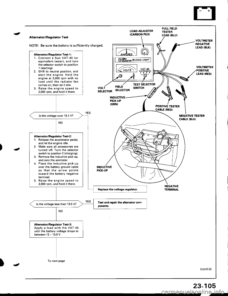
Alternator/Regulator Test
NOTE: 8e sure the battery is sufficiently charged.
LOAO ADJUSTER
ICARBON PILE)
FULL FIELDTESTERT.EAD (8LU)
POSITIVE TESTERCABLE IREDI
NEGATIVETERMINAL
VOLTMETERNEGATIVELEAO {BL|(}
VOLTMEIERPOSmVELEAD IREDI
FIELOSELECTOR
TEST SELECTORswtTcHVOLTSELECTOR
INDUCTIVEPICK.UP
INDUCTIVEPICK.UPIGRNI
NEGANVE TESTERCABLE IBLKI
)
)
{cont'd)
23-105
Ahernator/Regulator Tosl-1 :1. Connect a Sun VAT-40 (or
equivalent testerl, and turnthe selector switch to position'1 (starting).
2. Shift to neutral position, andstart the engine. Hold theengine at 3,000 rpm with noload until the radiator tancomes on, thon let it idle.3. Raise the engine sp€ed to2,000 rpm, and hold it there.
ls the voltage over 15.1 V?
Altsrnator/Rogulator Test-z:1. Release the accelerator pedal,
and let the engine idle.2, Make sure all accessories areturnod off. Turn the selectorswitch to position 2 (charging).
3. Remove the inductive pick-up,
and zero the ammeter.4. Place the inductive pick-up
over the battery ground cableso that the arrow points
toward the batterY negativeterminal,5. Raise the engine speed to2.000 rpm, and hold it there.
ls the voltage less than 13.5 V?
Ahelnstor/Regulator T$t-3iApply a load with the VAT-40until the battery voltage drops tobetween 12 - 13.5 V.
To next page
-
i-
Page 1173 of 1681
Fan Controls
RADIATORFANswtTcHTest, page 23-119
Component Location Index
For the A/C system, see section 22.
UNDER-HOODFUSE/RELAY BOX
CONDENSER FAN RELAYTest, page 23-69
RADIATOR FAN RELAYTest, page 23,69
FAN MOTORTest, page 23-119
TOR FAN MOTORTest, page 23,119
: lt tt tt tt l
c=, Ll L-t t lf l]-]l
f1 a l f -r a'r -
I i I r""""rlla-t fr -
a tL) | |Irt -
1/^ l/-\ltr.z{ N/ L
Page 1174 of 1681
Circuit Diagram (Without A/Cl
UNOEF.OASHFUSE,NELAY BOX
|-;ffi;I-YELf\-.rl]-t
BTK'EL -l
RAOIATORFANS\,YITCHfoN : above )(199'F (93'C)J
BLIVREO
BLK
I
G201G401
IGNITION SWITCH
N0.41 (lmAl No.42 (104)
RADIATORFANRELAY
23-117
.l
Page 1176 of 1681
)
Fan Motor Test
Disconnect the 2P connector from the fan motor.
Test the motor by connecting battery power to the
B terminal, and ground to the A termlnal.
lf the fan motor fails to run smoothly, replace it.
NOTE: The illustration shows the radiator fan.
Radiator Fan Switch Test
NOTE: Bleed air from the cooling system after installing
the radiator fan switch (see section 10)
1. Remove the radiator fan switch from the thermostat
housing.
2. Suspend the radiator fan switch in a container ol
coolanl as shown.
Heat the coolant and check engine coolant tempera
ture with a thermometer.
Check the continuity between the A and B terminals
according to the table:
23-119
Te rm Inal
Operatlon -------\
Tcmoerature ------
ON196. -203'F
(91" 95'C)
-5" 14.F i3" _8"C) ;*,*
than the temperature when
rt goes on.
SWITCH
OFF
B
-o
.-
Page 1319 of 1681

Cruise Gontrol
1.
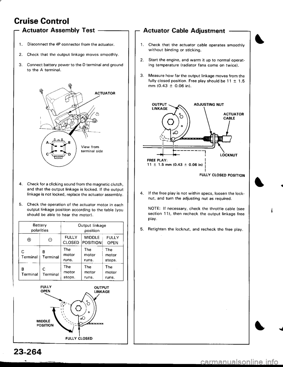
Actuatol Assembly Test
Disconnect the 4P connector from the actuator.
Check that the output linkage moves smoothly.
Connect battery power to the D terminal and ground
to the A terminal.
ACTUATOR
Check tor a clicking sound from the magnetic clutch.
and that the output linkage is locked. lf the outputlinkage is not locked, replace the actuator assembly.
Check the operation of the actuator moror In eacn
output linkage position according to the table (you
should be able to hear the motor).
FULLY CLOS€D
2.
3.
3.
23-264
Actuator Cable Adjustment
Check that the actuator cable operates smoothly
without binding or sticking.
Start the engine, and warm it up to normal operat-
ing temperature (radiator fans come on twice).
Measure how far the output linkage moves from thefully closed position. Free play should be 11 t 1,5mm (0.43 t 0.06 in).
FREE PLAY:1M.5 mm (0.43 1 0.06 in)
FULLY CLOSED POSITTON
4. lf the free play is not within specs, loosen the lock-
nut, and turn the adjusting nut as required.
NOTE: It necessary, check the throttle cable (see
section 1 1), then recheck the output linkage lreeplay.
5. Retighten the locknut, and recheck the free play.
^ffi"
c17i l,io
Battery
polaritiesOutput linkage
position
ooFULLY
CLOSED
MIDDLE
POSITION
FULLY
OPEN
c
Terminal
B
Terminal
The
moror
runs.
The
molor
runs.
The
motor
stops.
B
Terminal
c
Terminal
The
motor
stops.
The
motor
runs.
The
motor
runs.
{
Page 1383 of 1681

).1
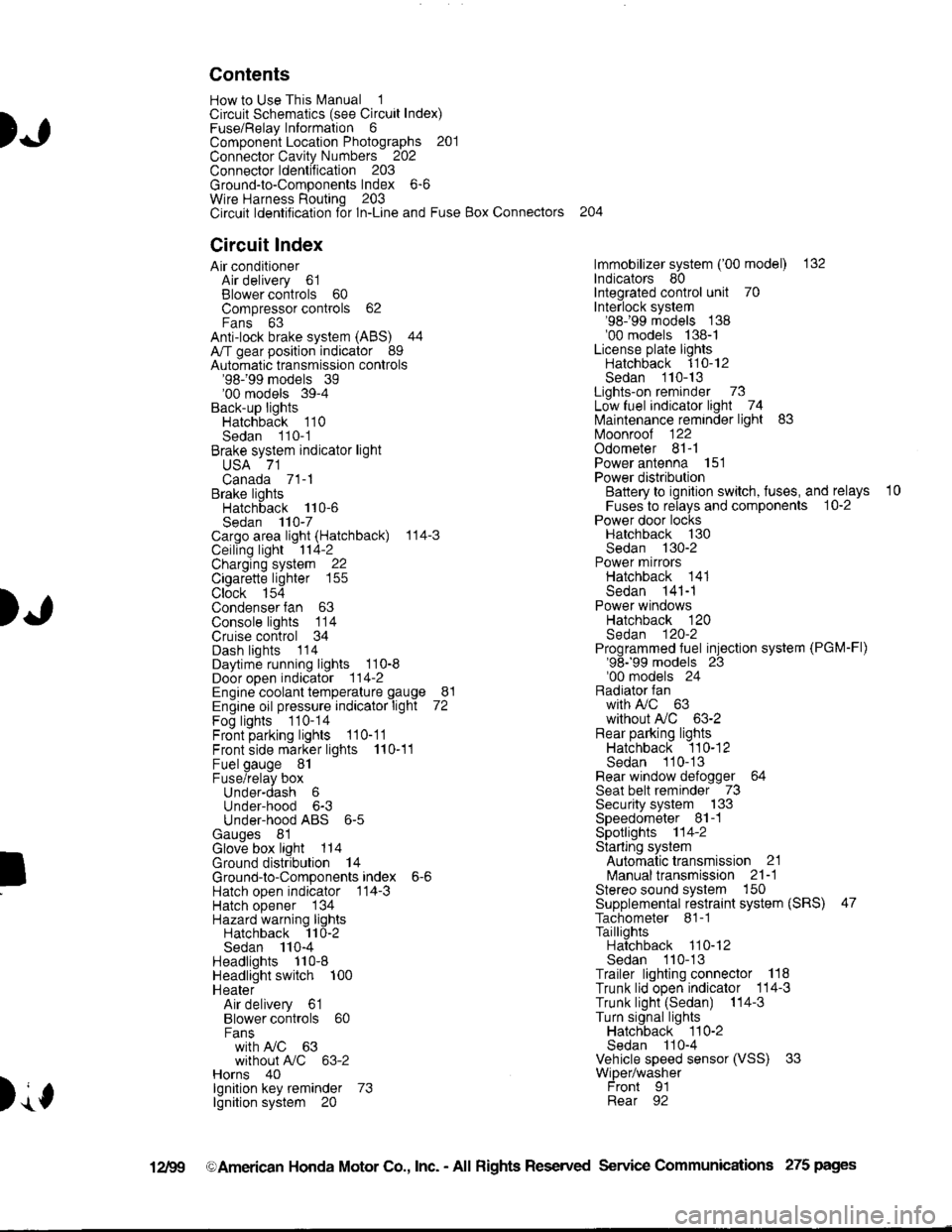
Contents
How to Use This l\.4anual 1Circuit Schematics (see Circuit Index)Fuse/Relaylnformation 6ComponentLocation Photographs 201
Connector Cavity Numbers 202Connectorldentification 203
Ground-to-Components Index 6-6Wire Harness Routing 203Circuit ldentification lor ln-Line and Fuse Box Connectors
Circuit Index
Air conditionerAir delivery 61Blower controls 60Compressor controls 62Fans 63Anti-lock brake system (ABS) 44A/T gear position indicator 89Automatic transmission controls'98199 models 39'00 models 39-4Back-up lightsHatchback 110Sedan 110- 1Brake system indicator light
USA 71Canada 71-1Brake lightsHatchback 110-6Sedan 110-7Cargo area light (Hatchback) 114-3Ceiling light 114-2Charging system 22Cigarette lighter 155
Clock 154Condenser fan 63Console lights 114Cruise control 34Dash lights 1 14Daytime running lights 110-8Door open indicator 114-2Engine coolant temperature gauge 81Engine oil pressure indicator light 72Fog lights 110-14Front parking lights 110-11Front side marker lights 110-11Fuel gauge 81Fuse/relay boxUnder-dash 6Under-hood 6-3Under-hood ABS 6-5Gauges 81Glove box light 114Ground distribution 14Ground-to-Componentsindex 6-6Hatch open indicator '114-3
Hatch opener '134
Hazard warning lightsHatchback 'l l0-2Sedan 110-4Headlights 1'10-8Headlight switch 100HeaterAir delivery 61Blower controls 60Fanswith A,/C 63without A,/C 63-2Horns 40lgnilion key reminder 73lgnition system 20
204
lmmobilizer system ('00 model) 132lndicators 80Integrated control unit 70Interlock system'98199 models 138'00 models 138-1License plate lightsHatchback 110-12Sedan 110-13Lights-on reminder 73Low fuel indicator light 74l\,4aintenance reminder light 83l\iloonroof 122Odometer 81-1Power antenna 151Power distributionBattery to ignilion switch, fuses, and relays
Fuses to relays and components 10-2Power door locksHatchback '130
Sedan 130-2Power mirrorsHatchback 141Sedan 141-1Power windowsHatchback 120Sedan 120-2Programmed fuel injection system (PGM-Fl)'98199 models 23'00 models 24Radiator fanwith tuC 63without A,/C 63-2Rear parking lightsHatchback 110-12Sedan 110- 13Rear window defogger 64Seat belt reminder 73Security system 133Speedometer Il-1Spotlights 114-2Starting syslemAutomalictransmission 21l\.4anualtransmission 21-1Stereo sound system 150Supplemental restraint system (SRS) 47Tachometer 81- 1TaillightsHatchback 110-12Sedan 110-13Trailer lighting conneclor 118Trunk lid open indicator 114-3Trunk light (Sedan) 114-3Turn signal lightsHatchback 110-2Sedan 110-4Vehicle speed sensor (VSS) 33Wiper/washerFront 91Rear 92
10
).1
I
Xr
12Fg oAmerican Honda Motor Co., Inc. - All Rights Reserved Service Communications 275 pages
Page 1404 of 1681

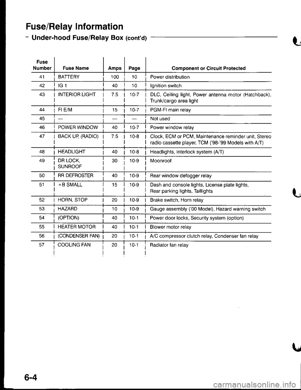
Fuse/Relay I nformation
- Under-hood Fuse/Relay Box (cont'd)
Fuse
NumberFuse NameAmpsPage
BATTERY
I INTERIOR LIGHT
I
1 7.5 110-7 I
I
Component or Circuil Protected
Power distribution
lgnition switch
DLC, Ceiling light, Power antenna motor (Hatchback),
Trunk/cargo area light
47
I Fl E/lvl
POWER WINDOW
I BACK UP (RADTO)
I
15 | 1 0-7 I PGM-FI main relay
Not used
Power window relay
Clock, ECM or PCM, Maintenance reminder unit, Stereo
radio cassette player, TCM ('98-'99 Models with A'/T)
7.5 |10-8
I HEADLIGHT| 40 | 10-8 | Headlights, Interlock system (A/T)
49i DR LOCK,
i suNRooF
10-9 i Moonroof
I
I RR DEFROSTER
+ B SMALL
I Rear window detogger relay
I Dash and console lights, License plate lights,
I Rear parking lights, Taillights
I HORN, STOP
i HAZARD
10-9 | Brake switch, Horn relay
i Gauge assembly ('00 Model), Hazard warning switch
40 | to t I Power door locks, Security system (option)
I HEATER MOTOR II t 0-1I Blower motor relay
20 I 10-1 ; A,/C compressor clutch relay, Condenser fan relay
i Radiator fan relay1 0-1
6-4