1998 HONDA INTEGRA radiator
[x] Cancel search: radiatorPage 1604 of 1681
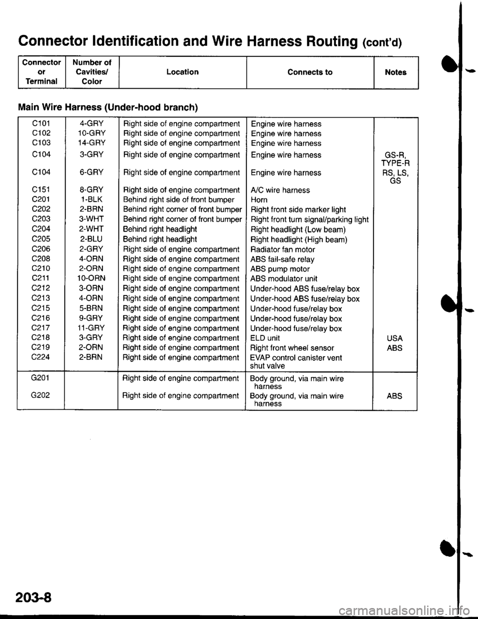
Connector ldentification and Wire Harness Routing (conrd)
Connector
ot
Terminal
Number of
Cavities,/
Color
LocationConnects toNotes
Main Wire Harness (Under-hood branch)
c101
c102
cl03
c104
c104
c151
c201
c202
c203
c204
c205
c206
c208
c210
c211
c212
c213
c215
wz to
c217
c218
c219
4-GBY
1O.GRY
14.GRY
3-GRY
6-GRY
8.GRY
1-BLK
2-BRN
3.WHT
2-WHT
2-BLU
2-GRY
4-ORN
2-ORN
10-oRN
3-ORN
4-ORN
5.BRN
9.GRY
11-GBY
3-GBY
2-ORN
2-BRN
Right side of engine compadment
Right side of engine compartment
Right side of engine compartment
Right side of engine compartment
Right side of engine compartment
Right side of engine compartment
Behind right side of front bumper
Behind right corner of front bumper
Behind right corner of front bumper
Behind right headlight
Behind right headlight
Right side of engine compartment
Righl side of engine compartment
Right side of engine compartment
Bight side of engine compartment
Right side of engine compartment
Right side of engine compartment
Right side of engine compartment
Right side of engine companment
Right side of engine compartment
Right side of engine compartment
Right side of engine compartment
Right side of engine compartment
Engine wire harness
Engine wire harness
Engine wire harness
Engine wire harness
Engine wire harness
A,/C wire harness
Horn
Right f ront side marker light
Right front turn signal/parking light
Right headlight (Low beam)
Right headlight (High beam)
Radiator fan motor
ABS faiFsafe relay
ABS pump molor
ABS modulator unit
Under-hood ABS fuse/relay box
Under-hood ABS tusehelay box
Under-hood fuse/relay box
Under-hood fuse/relay box
Under-hood fuse/relay box
ELU UNII
Right front wheel sensor
EVAP control canister vent
shut valve
GS.R,
TYPE-R
RS, LS,
GS
USA
ABS
Right side of engine compartment
Right side of engine compartment
Body ground, via main wire
harness
Body ground, via main wireharnessABS
2()3€
Page 1641 of 1681
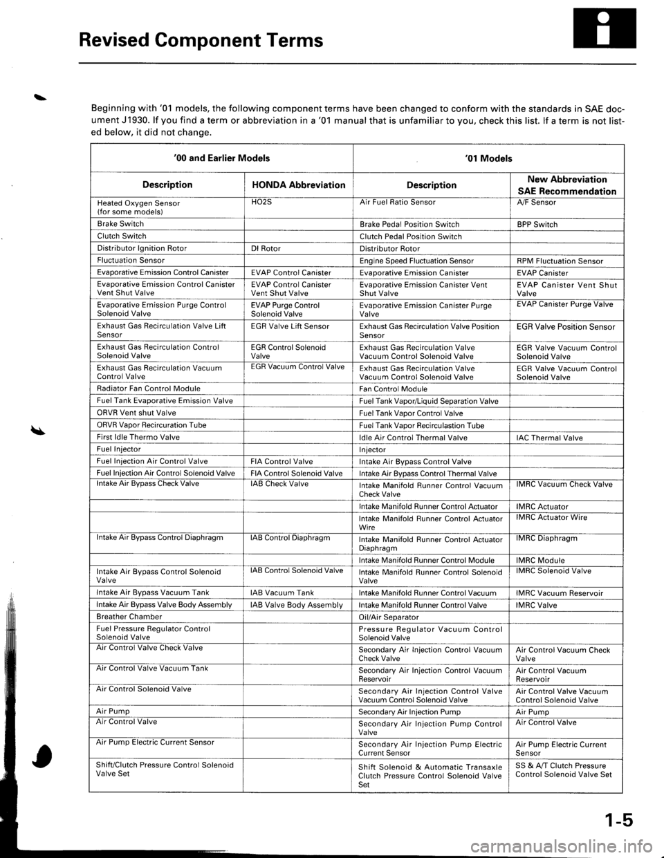
Revised Component Terms
\
\
Beginning with '01 models, the following component terms have been changed to conform with the standards in SAE doc-
ument J1930. lf you find a term or abbreviation in a '01 manual that is unfamiliar to you, check this list. lf a term is not list-
ed below, it did not chanqe.
'00 and Earlier Models'01 Models
DescriptionHONDA AbbreviationDescriptionNew Abbreviation
SAE Recommendation
Heated Oxygen Sensor(for some models)HO2SArr ruet llalto )ensorA,/F Sensor
Brake SwitchBrake Pedal Position SwitchBPP Switch
Clutch SwitchClutch Pedal Position Switch
Distributor lgnition RotorDl RotorDistributor Rotor
Fluctuation SensorEngine Speed Fluctuation SensorRPM Fluctuation Sensor
Evaporative Emission Control CanisterEVAP Control CanisterEvaDorative Emission CanisterEVAP Canister
Evaporative Emission Control CanisterVent Shut ValveEVAP Control CanisterVent Shut ValveEvaporative Emission Canister VentShut ValveEVAP Canister Vent ShutValve
Evaporative Emission Purge ControlSolenoid ValveEVAP Purge ControlSolenoid ValveEvaporative Emission Canister PurgeValveEVAP Uanister Purge Valve
Exhaust Gas Recirculation Valve LiftSensorEGR Valve Lift SensorExhaust Gas Recirculation Valve PositionSensorEGR Valve Position Sensor
Exhaust Gas Recirculation ControlSolenoid ValveEGR Control SolenoidValveExhaust Gas Recirculation ValveVacuum Control Solenoid ValveEGR Valve Vacuum ControlSolenoid Valve
Exhaust Gas Recirculation VacuumControl ValveEGR Vacuum Control ValveExhaust Gas Recirculation ValveVacuum Control Solenoid ValveEGR Valve Vacuum ControlSolenoid Valve
Radiator Fan Control ModuleFan Control Module
Fuel Tank Evaporative Emission ValveFuel Tank Vapor/Liquid Separation Valve
ORVR Vent shut ValveFuel Tank Vaoor Control Valve
ORVR Vaoor Recircuration TubeFuel Tank Vaoor Recirculastion Tube
First ldle Thermo Valveldle Air Control Thermal ValveIAC Thermal Valve
Fuel InjectorI njector
Fuel Iniection Air Control ValveFIA Control ValveIntake Air Bypass Control Valve
Fuel Injection Air Control Solenoid ValveFIA Control Solenoid ValveIntake Air Bypass Control Thermal Valvelntake Air BvDass Check ValveIAB Check ValveIntake Manifold Runner Control VacuumCheck ValveIMRC Vacuum Check Valve
Intake Manifold Runner Control ActuatorIMRC Actuator
Intake Manifold Runner Control ActuatorWireIMRC Actuator Wire
ntake Air Bypass Control DiaphragmIAB Control DiaphragmIntake Manifold Runner control ActuatorDiaphragmilvrr1u urapnragm
Intake Manifold Runner Control ModuleIMRC Module
Intake Air Bypass Control SolenoidValvelAts Control Solenoid ValveIntake Manifold Runner Control SolenoidValveIMRC Solenoid Valve
Intake Air Bvpass Vacuum TankIAB Vacuum TankIntake Manifold Runner Control VacuumIMRC Vacuum Reservoir
Intake Air Bypass Valve Body AssemblyIAB Valve Body AssemblVIntake Manifold Runner Control ValveIMRC Valve
Breather ChamberOil/Air Separator
Fuel Pressure Regulator ControlSolenoid ValvePressure Regulator Vacuum ControlSolenoid ValveAir Control Valve Check ValveSecondary Air In.jection Control VacuumCheck ValveAir Control Vacuum CheckValveArr Control Valve Vacuum TankSecondary Air Injection Control VacuumReservoirAir Control VacuumReservoirAir Control Solenoid ValveSecondary Air Injection Control ValveVacuum Control Solenoid ValveAir Control Valve VacuumControl Solenoid Valve
Air PumpSecondary Air Injection PumpAir PumpAir Control ValveSecondary Air Injection Pump ControlValveAir Control Valve
Arr rump tsreclnc uurrent bensorSecondary Air Injection Pump ElectricCurrent SensorAir Pump Electric CurrenlSensor
Shift/Clutch Pressure Control SolenoidValve SetShift Solenoid & Automatic TransaxleClutch Pressure Control Solenoid ValveSet
SS & A,/T Clutch PressureControl Solenoid Valve Set
1-5
Page 1648 of 1681
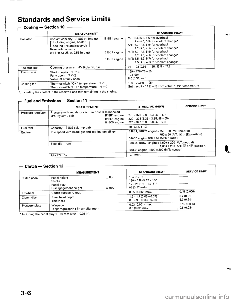
Standards and Service Limits
missions - Section 11
* Including the pedal play 1 - 10 mm (0.04 - 0.39 in).
0Gooling - Sectlon
MEASUREMENTSTANDARD (NEW}
RadiatorCoolant capacity / (US qt, lmp qt) 81881 engine
I Including engine, heater, II cooling line and reservoir IReservoir capacity:0.6 f (0.63 US qt, 0.53 lmp qt) 818C1 engine
818C5 engine
M/T: 6.4 (6.8, 5.6) for overhaul4.4 14.6,3.9) for coolant change*
A,/T: 6.7 (7.1, 5.9) for overhaul4.7 $.0,4.1)for coolant change*
M/T: 6.7 (7.1,5.9) for overhaul4.7 (5.0, 4.1) for coolant change*
M/T: 6.5 (6.9, 5.7) for overhaul4.5 (4.8, 4.0) for coolant change*
Radiator capOpening pressure kPa (kgf/cm'�, Psi)93 - 123 (0.95 - 1.25, 13.5 - 17.8)
ThermostatStart to open 'F ("C)
Fully open "F ("C)
Valve lift at fully open
169 - 176 (76 - 80)194 (90)
8.0 (0.31)min.
Cooling fanThermoswitch "ON" temperature "F ('C)
Thermoswitch "OFF" temperature "F ("C)196 - 203 (91 - 95)Subtract 5 - 14 (3 - 8) from actual "ON" temperature
*: Including the coolant in the reservoir and that remaining in the engine
Fuel and E
MEASUREMENTSTANDARD (NEW}SERVICE LIMIT
Pressure regulatorPressure with regulator vacuum hose disconnected
kPa (kgf/cm'�, psi) 81881 engine818C1 engine818C5 engine
270 - 320 (2.8 - 3.3, 40 - 47].
329 - 378 (3.35 - 3.85, 48 - 55)
320 - 370 (3.3 - 3.8, 47 -541
Fuel tankCapacity / (US gal, lmp gal)50 (13.2, 11.0)
Engineldle speed with headlight and cooling fan off rpm81881, 818C1 engines 750 t 50 (M/T: neutral)750 I 50 (A/T: N or E Position)818C5 engine 800 t 50 (M/T: neutral)
Fast idle rpmB1881, 818C1 engines 1,600 t 200 (M/T: neutral)1,600 t 200 (A/T: E or E Position)818C5 engine 1,500 t 200 (M/T: neutral)
ldle CO %0.1 max.
Clutch - Section 'lZ
MEASUREMENTSTANDARD (NEW}SERVICE LIMIT
Clutch pedalPedal height to floor
StrokePedal playDisengagement height to floor
164 (6 7/16)130 - 140 (5.12 - 5.51)12 -21 (12 - 13/16)*83 (3.27) min.
FlywheelClutch surface runoul0.05 (0.002) max,0.15 (0.006)
Clutch discRivet head depthThickness
1.2 - 1.7 (0.05 - 0.07)8.3 - 9.0 (0.33 - 0.35)0.2 (0.01)
6.0 (0.24)
Pressu re plateWarpageDiaphragm spring finger alignmenl
0.03 (0.001) max.0.6 (0.021 max.
0.15 (0.006)
0.8 (0.03)
3-6
Page 1670 of 1681
Cooling
Radiator
Engine Coolant Refilling and
Bfeeding .... 10-2
NOTE: Refer to the '98 INTEGRA Service Manual, PiN 61ST705, for the
items not shown in this section.
,f
Outline of ModelChange
Engine coolant has been changed.
rfltmlfr
Page 1671 of 1681
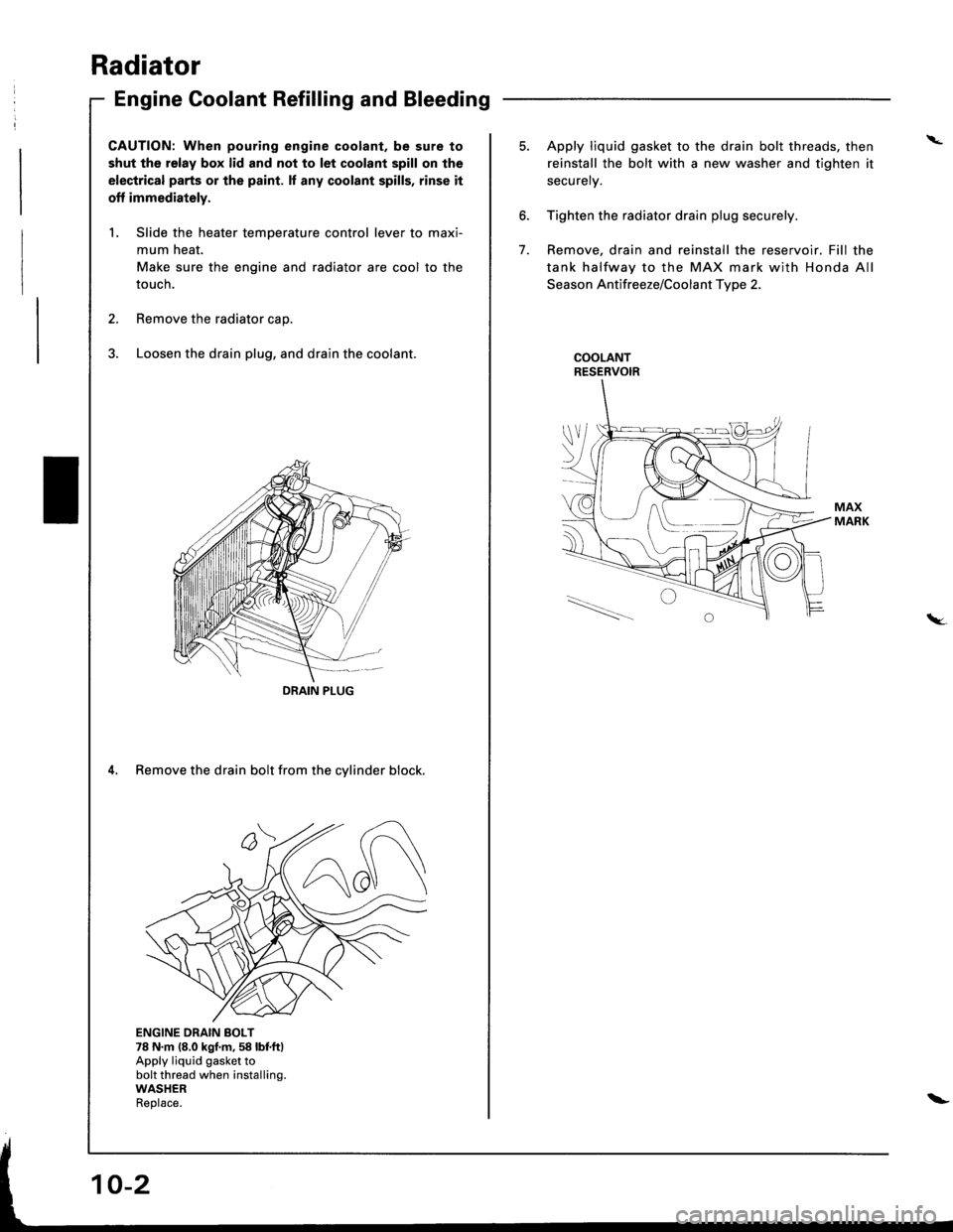
Radiator
Engine Goolant Refilling and Bleeding
CAUTION: When pouring engine coolant, be sure to
shut the relay box lid and not to let coolant spill on the
electrical parts or the paint. lf any coolant spills, rinse it
off immediately.
1. Slide the heater temperature control lever to maxi-
mum heat.
Make sure the engine and radiator are cool to the
touch.
2. Remove the radiator caD.
3. Loosen the drain plug, and drain the coolant.
4. Remove the drain bolt from the cylinder block.
ENGINE DRAIN BOLT78 N.m (8.0 kgf.m,58 lbf.ftlApply liquid gasket tobolt thread when installing.WASHERReolace.
DRAIN PIUG
I \.--
\_-l - I
\
6.
7.
5. Apply liquid gasket to the drain bolt threads, then
reinstall the bolt with a new washer and tighten it
securely.
Tighten the radiator drain plug securely.
Remove, drain and reinstall the reservoir. Fill the
tank halfway to the MAX mark with Honda All
Season Antifreeze/Coolant Type 2.
COOLANTRESERVOIR
tW.
\-
Page 1672 of 1681
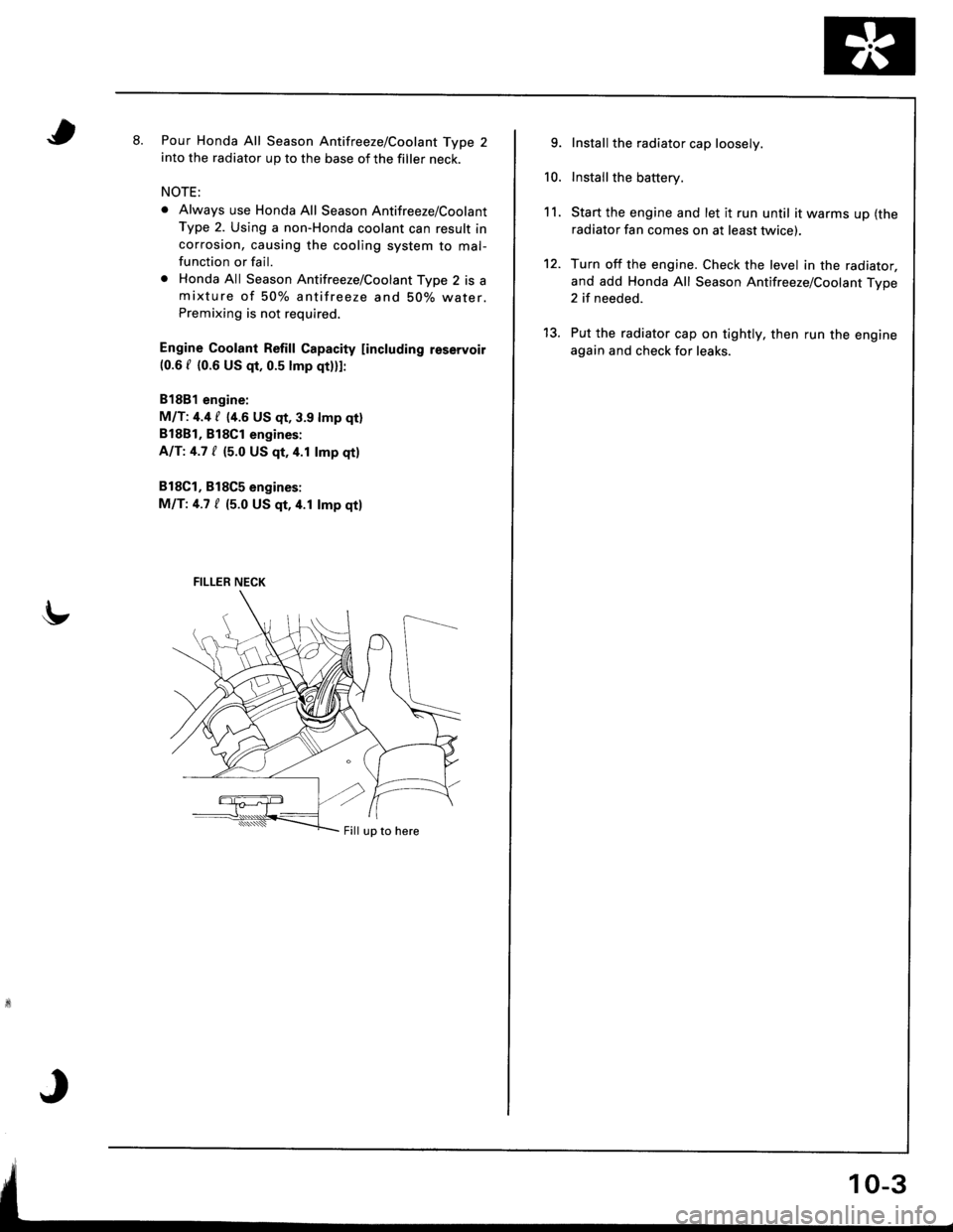
tt.Pour Honda All Season Antifreeze/Coolant Type 2into the radiator up to the base of the filler neck.
NOTE:
o Always use Honda All Season Antifreeze/Coolant
Type 2. Using a non-Honda coolant can result incorrosion, causing the cooling system to mal-function or fail.
o Honda All Season Antifreeze/Coolant Type 2 is amixture of 50% antifreeze and 50% water.Premixing is not required.
Engine Coolant Refill Gapacity [including reservoir(0.6 f {0.6 US qt, 0.5 lmp qtlll:
81881 engine:
M/T: 4.4 / {4.6 US qt, 3.9 lmp qtl
B18B1, Bl8Cl engines:
AIT:4.7 / (5.0 US qt,4.1 lmp qtl
818C1, B18C5 engines:
MIT:4.7 / (5.0 US qt,4.1 lmp qtl
FILLER NECK
Fill up to here
9.
10.
11.
12.
Install the radiator cap loosely.
Install the battery.
Start the engine and let it run until it warms up (the
radiator fan comes on at least twice).
Turn off the engine. Check the level in the radiator,
and add Honda All Season Antifreeze/Coolant Type2 if needed.
Put the radiator cap on tightly, then run the engine
again and check for leaks.
13.