1998 HONDA INTEGRA heater
[x] Cancel search: heaterPage 1406 of 1681
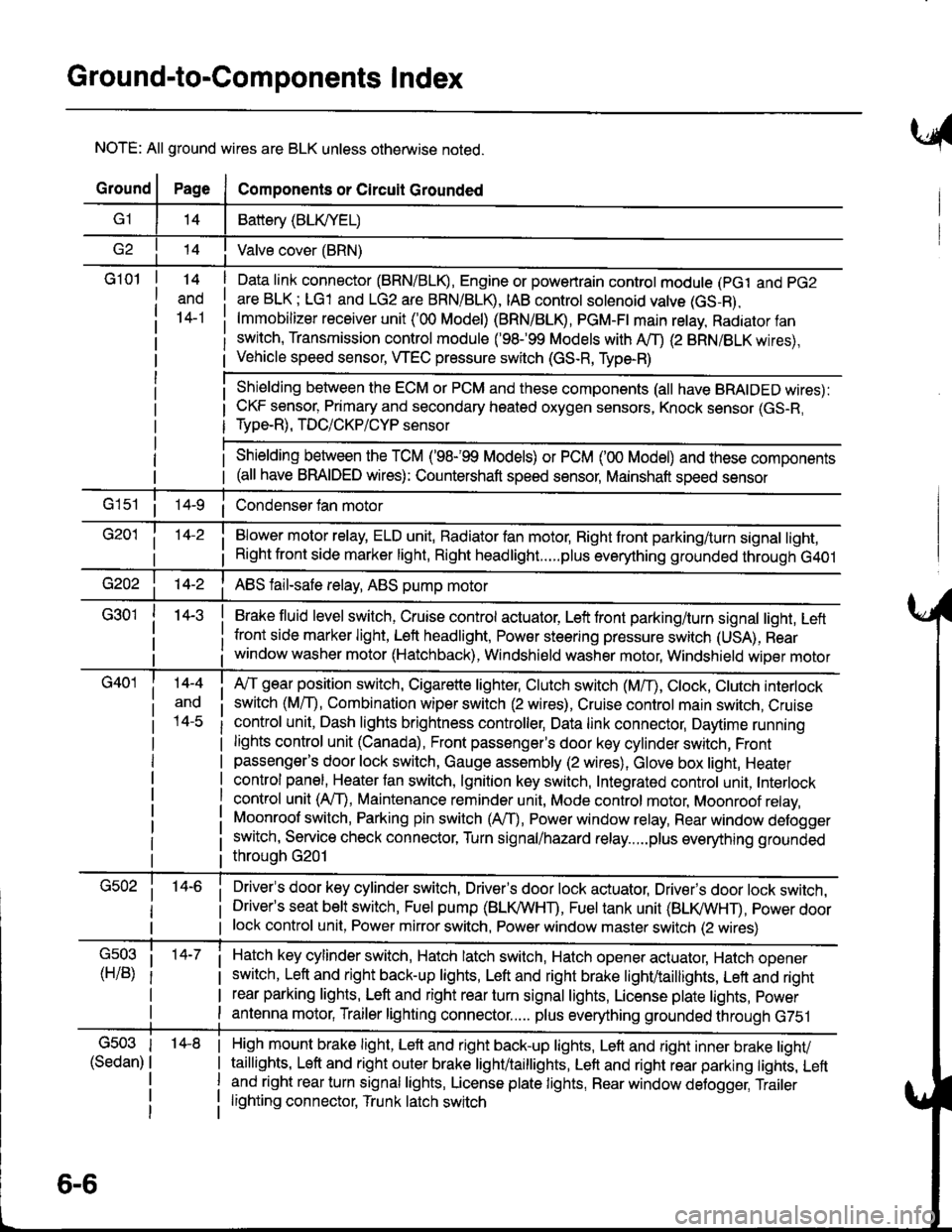
Ground-to-Components I ndex
NOTE: All ground wires are BLK unless otherwise noted.
GroundPageComponents or Circuit Grounded
Battery (BLIVYEL)
--t'I Valve cover (BRN)
G101t.+
and
14-1
Daia link connector (BRN/BLK), Engine or powertrain controt module (pct and pG2
are BLK; LG1 and LG2 are BRN/BLR, IAB controt solenoid valve (GS-B),
lmmobilizer receiver unit ('00 Model) (BRN/BLR, PGM-Ft main retay, Radiator fan
switch, Transmission control module ('98.�99 Models with MD (2 BRN/BLK wires),
Vehicle speed sensor, WEC pressure switch (GS-R, Type-R)
Shielding between the ECM or PCM and these components (all have BRAIDED wires):
CKF sensor, Primary and secondary heated oxygen sensors, Knock sensor (GS-R,
Type-R), TDC/CKP/CYP sensor
Shielding between the TCM ('98-'99 Models) or PCM ('00 Model) and these components(all have BRAIDED wires): Countershaft speed sensor, Mainshaft speed sensor
G1s1 ii Condenser fan motor
Brake fluid level switch, Cruise control actuator, Left front parking/turn signal light, Left
front side marker light, Left headlight, Power steering pressure switch (USA), Rear
window washer motor (Hatchback), Windshield washer motor, Windshield wiper motor
14-3
Blower motor relay, ELD unit, Badiator fan motor, Right front parking/turn signal light,
Right front side marker light, Right headlight.....plus everything grounded through G401
ABS fail-safe relay, ABS pump motor
G40114-4
ano
l4-c
A,/T gear position switch, Cigarette lighter, Clutch switch (M,/T), Ctock, Ctutch interlock
switch (MfD, Combination wiper switch (2 wires), Cruise control main switch, Cruise
control unit, Dash lights brightness controller, Data link connector, Daytime running
lights control unit (Canada), Front passenger's door key cylinder switch, Frontpassenger's door lock switch, Gauge assembly (2 wires), Glove box light, Heater
control panel, Heater tan switch, lgnition key switch, Integrated control unit, Interlock
control unit (AfI), Maintenance reminder unit, Mode control motor, Moonroof relay,
Moonroof switch, Parking pin switch (AfD, Power window relay, Rear window defogger
switch, Service check connector, Turn signal/hazard relay.....plus everything grounded
throuoh G201
Driver's door key cylinder switch, Driver's door lock actuator, Drivels door lock switch,Driver's seat belt switch, Fuel pump (BLI(/WHT), Fuel tank unit (BLI(/WHT), power doorlock control unit, Power mirror switch, Power window master switch (2 wires)
Hatch key cylinder switch, Hatch latch switch, Hatch opener actuator, Hatch ooener
switch, Left and right back-up lights, Left and right brake light/taillights, Lett and right
rear parking lights, Left and right rear turn signal lights, License plate lights, power
antenna motor, Trailer lighting connector..... plus everything grounded through G751
6-6
'14-8G503
(Sedan)
High mount brake light, Left and right back-up lights, Lett and right inner brake tighv
taillights, Left and right outer brake light/taittights, Left and right rear parking tights, Leftand right rear turn signal lights, License plate lights, Rear window detogger, Trailer
lighting connector, Trunk latch switch
Page 1414 of 1681
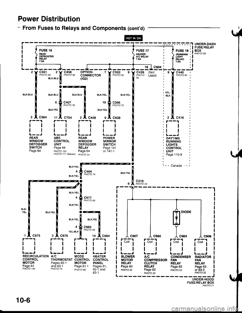
Power Distribution
- From Fuses to Relays and Components (cont'd)
FU'E 16 Err*rrilnEAR tEArEn : tFurflnc ,:oEFFosrER { flfo"t-t i { l'rtTr :!7.5A I : I 7.5a ,l
ffi-.^,; l:lL - - L __ _ _ J_ _ _ _ _ J __ _ _ I _ __ _ J _ _ 16 J9:91 L _L _ _ _:i'tr F"?%,, 'tr'F"Xlg", 331'$A"'o* ' f F;03,, ' lf ;'"11'" {H!, i ' f t"X13,, :
I eLxaLul (rcrt'--'-' I 16z
""""'
i I :
r:_lrl:
":1",-:ri;:t
ll".",:{.tFz'€; I lll".,. i
rt i'--t rt i--t i ;i--i i
t__J t__l r__J !._-J ! i t__.t iBEAR ABS REAR POWER II ' DA\.TIME ;wrNDow coNTRoL wtNDow MtRRoB I : RUNNTNGoEFoccER uNrr DEFoccER swtrcH It ; LtcHTsSWITCH Page 44 RELAY paoe 141 I , CONTROL :Page 64 pHoro 1oo Page 64 or i41-t [ ' Uttf :PHoro111\sedan) pHoro5a
! j Page 110-9
|
! l-- canada.- it*rarffi'
"JI.f t*', u..^""1
-.
)t .,1, r*,.
BLK,YEL
BLK,YEL
ml'"
]"*.r-A?1
t*"1
tl
BLOWENMOTORBELAYPage 60Pttofo 22
rF^;'l
t*l
tl
Atc
UNDER-DASHFUSE/RELAYBOX
c677
L--J |.--J L--JA/C MODE HEATERTHERMOSTAT CONTBOL CONTROI.Pages 62-1 MOTOR PANELand 63.1 Paqe 61 I Paoes61.PHO|O zJ psiro aa 62--1 and63'1
r'--?1 r;^;'r
t*"lt*"1
tttlL--J L--JCONDENSER NADIATORCOMPRESSOR FANCLUrcHBELAYPage 62
RELAYPage 63
FANRELAYPags 63or 63-2PHA|O )3 PHO|O 22 i------JUNDER-HOODFUSE/RELAY BOXPHQ|O2l
@
10-6
Page 1440 of 1681
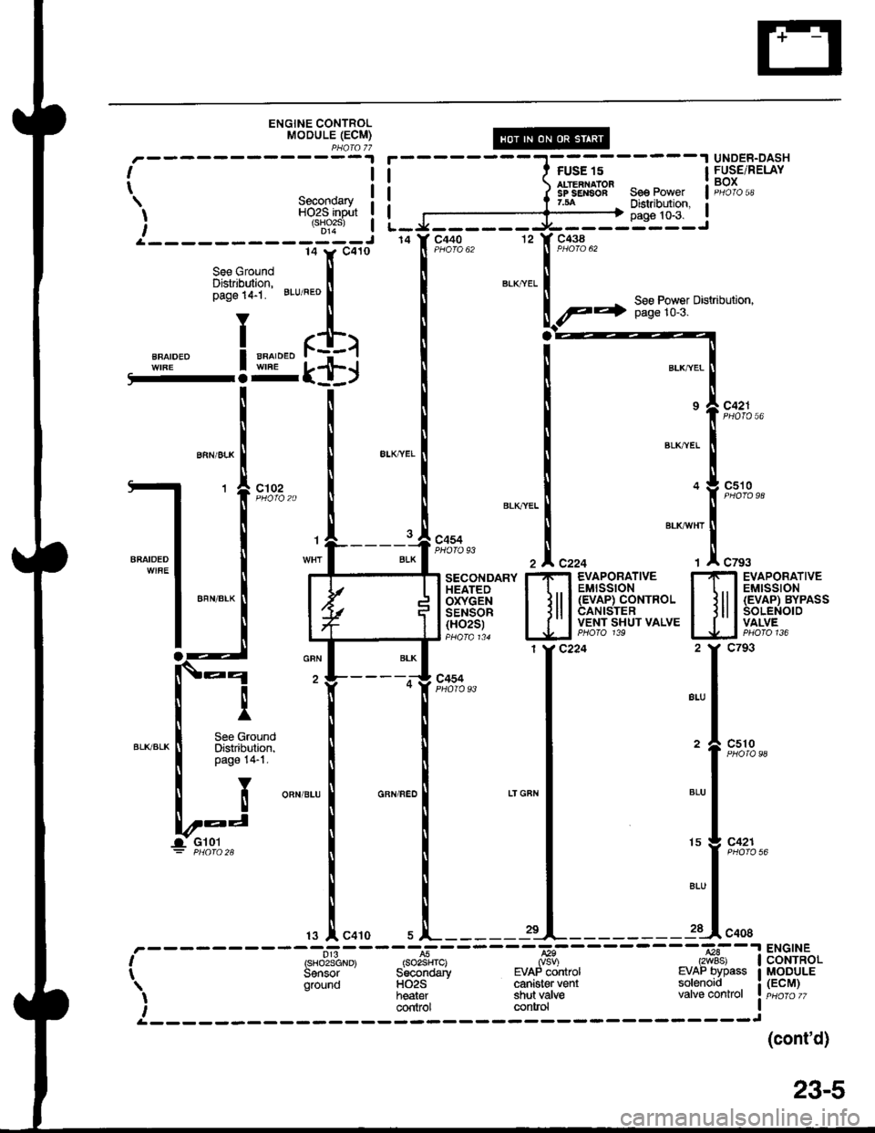
ENGINE CONTROLMOOULE (ECM)PHOfa 77
ll
tSecondaryHO2S input{sHo2s)D14i-------------J
FUSE 'I5
ALTERNATOFSP SENSOF
UNDER-DASHFUSE/RELAYBOX
12
See PowerDistfibution,
--':':'5 ic438la Y calo
See Ground IDistribution, llpage 14-1 BLuiFEo I
YT
BFA,DED ! u"o'o.o r$l
LTSL+J
See Power Distribution,page 10-3.
gLKAVHT
I
""^,"*
I
-l 'fir*"
*^lt:: | !
I
-""-
|
!J
["r
I See GroundBrK/BLK
I
o":o,T:il
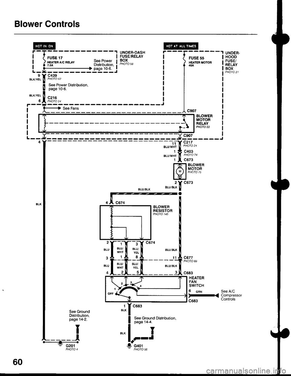
Blower Controls
FUSE 17HE TEn ,'/C nELAY7.5ASee PowetDistribution,page 10-6.
UNDER.DASHFUSE/RELAYBOX
---G;;-'
/ HEATER I'OTOR
l*^
I
I
I
---1"*'
UNOER.HOODFUSE/RELAYBOXL - y' - - - - - - - -:: - - J9 Y C439.KryEL ! P/roro 62BLK|/EL ll PHOIO 62
BLOVYERMOTORFELAYPHOTO 22
9s_____i
".u-", f, i'ii'o '.
1 l c6z3
Hfib#i
".,,".?[ "ut'
- -i;a' c217BLU 1,vi{r
J
PHoro '�u
C677PHOTO 69:rI#
c683
HEATERFANswtTcH
6 cnr
)-<
See A/CCompressorControls
1BLKc683
See Ground Distribution,page 14-4.
I
J
See GroundOistribution,page 14-2.
: G201
60
Page 1476 of 1681
Air Deliver| (cont'd)
- How the Circuit Works
The air delivery system directs the flow of air used
by the heater and air conditioner systems.
Mode Selection
Mode selection is controlled by the mode switches in
the heater control panel and the mode control motor.
When you select a specific mode, voltage is applied
through the dimming control circuit to the LED, which
comes on, indicating the mode selected. Ground is
provided to the mode control motor though that
mode switch. The motor then runs until the air
control door reaches the proper position.
Fresh/Recirculation Selection
When you press the recirculation button, a ground
signal is sent from the heater control panel to the
recirculation control motor. The motor lhen runs
until the recirculation door reaches the opposite
Dosition. When the recirculation button is in the
REC position, battery voltage is applied through the
dimming control circuit to the recirculate LED, and
the LED comes on.
Refer to the Service Manual (Section 21, Heate0 for
specif ic tests or troubleshooting procedures.
61-2
Page 1479 of 1681
A/C Gompressor Controls (conrd)
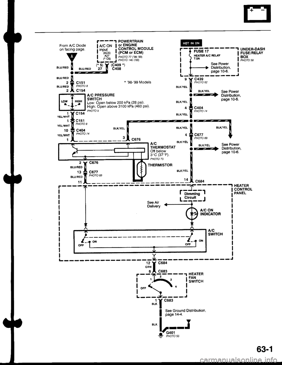
- How the Circuit Works
Battery voltage is supplied through fuse 56 to the
A,/C compressor clutch relay contacts at all times.
With the ignition switch in ON (ll), voltage is applied
to the coil of the A,/C compressor clutch relay
through fuse 17. When you push the A,/C switch
ON, and the heater fan switch is in posation 1, 2, 3,
or 4, a "ground" input is provided to the engine or
powertrain control module (ECM or PCM) through
the A,/C thermostat and the A,/C pressure switch.
The A,/C compressor clutch relay is grounded by the
engine or powertrain control module (ECM or PCM).
When energized, the A,/C compressor clutch relay
allows battery voltage to turn on the A,/C
comDressor clutch,
The A,/C ON indicator light comes on when the A"/C
system is requested.
A,/C Thermostat
The A,/C thermostat is located on the evaoorator
housing. The AJC thermostat turns off the A,/C
compressor clutch if the temperature at the
evaporator goes below 3'C (37'F). This prevents
condensation from freezing on the evaporator fins
and blocking the air delivery into the passenger
compartment. The blower motor will keep running
when the sensor lurns off the compressor.
A,/C Pressure Switch
The A,/C pressure switch is located in the condenser
outlet line where refrigerant is in a high
temperature/high pressure liquid state. The switch
will sense abnormally high or low pressure, and
open the circuit. This removes ground, and the
compressor will stop running.
Refer to the Service Manual (Section 22,
Air Conditioning) for specific tests or
troubleshooting procedures.
62-2
Page 1481 of 1681
From IVC Diodeon facing page.
v
".r,".o ! ".u,".o
1 YCls4 '- --
"t"*1t ,I, ^..,
-t'I:::'
ri'fft_____:_
POWERTRAIN
! *'"P* ! 3b'nli?3'-"oou'.I rAcs' I {PCM or ECM}
| ,S1, I iuorozz $a.ssiLJ:LJ PHora 14a too)IIEATES IJC RELAY?54
UNDER.DASHFUSE/RELAYBOXPHO|O 58
r 5) Y (C409 *)
27 n c408
See PowerDistribution,page 10-6.a
";;;ic151
c154
* '98'�99 Models
I'lC PRESSURESWITCHLow: Open below 200 kPa (28 Psi).High: Open above 3100 kPa (460 Psi).
.4
See Po' erDistribution,page 106,
See PoworDbtribution,page 1G6.
A/CTHERMOSTATOfl below3'c (37"F).
THERMISTOR
S€e AirDelivery
"a*a, i
*,*rfrs,*lt-
a
BTK,"VEI i
9:1L"" t
::;1".,.
I Dimmlng t
-.I HEATER,J--- I cONrR(CONTROL
Circult
r,/c oNINDICATOR
".1r "ur'
I 8:8ffiTo
o'"u''"''n'
*!r".-
F--9*l:93----r HEATER
!iIA{. lSiii,"'.
L:5-l--i
63-1
Page 1483 of 1681
Fans (cont'd)
- How the Gircuit Works
When the ignition switch is in ON (ll), voltage is
applied to the coils of the radiator fan relay and the
condenser fan relay (with A,/C) through fuse 17.
Whenever a ground is provided to the radiator fan
relay and condenser fan relay, the relays are
energized, turning on the radiator fan motor and
condenser fan motor. The relays can be grounded
by the radiator fan switch, engine or powertrain
control module (ECM or PCM) (USA), or the A,/C
and heater lan switches via the A'lC pressure switch
and the A,/C lhermostat.
A,/C Thermostat
The A,/C thermostat is located on the evaporator
housing. The A/C thermostat turns oft the A/C
compressor clutch it the temperature at the
evaporator goes below 3'C (37"F). This prevents
condensalion from freezing on the evaporator fins
and blocking the air delivery into the passenger
compartment. lt the temperature goes below 3'C
(37'F) turning off the A"/C thermostat, and the
BLU/RED wire at the A,/C diode was the only wire
providing ground to the condenser and radiator
fan relays (A,/C switch on, heater fans switch on,
radiator fan switch open, and ECM or PCM fan
controi output not grounded), the relay will
deenergize removing voltage from the condenser
and radiator fan motors causing them to stop
running.
A,/C Pressure Switch
The AJC oressure switch is located in the condenser
outlet line where refrigerant is in a high
temperature/high pressure liquid state. The A,/C
switch turns off the A,/C compressor clutch if it
senses abnormally high or low pressure. lf the A'lC
pressure switch opens, and the BLU/RED wire at
the A/C diode was the only wire providing ground
to the condenser and radiator fan relays (L/C switch
on, heater fans switch on, radiator lan switch open'
and ECM or PCM fan control output not grounded),
the relay will deenergize removing voltage from the
condenser and radiator fan motors causing them to
stop running.
A./C Diode
This diode orevents the radiator fan switch f rom
grounding the "A'lC ON" input to the engine or
powertrain control module (ECM or PCM).
Refer to the Service Manual (Section 23, Electrical)
for specific tests or troubleshooting procedures.
63-3