Page 1014 of 1681
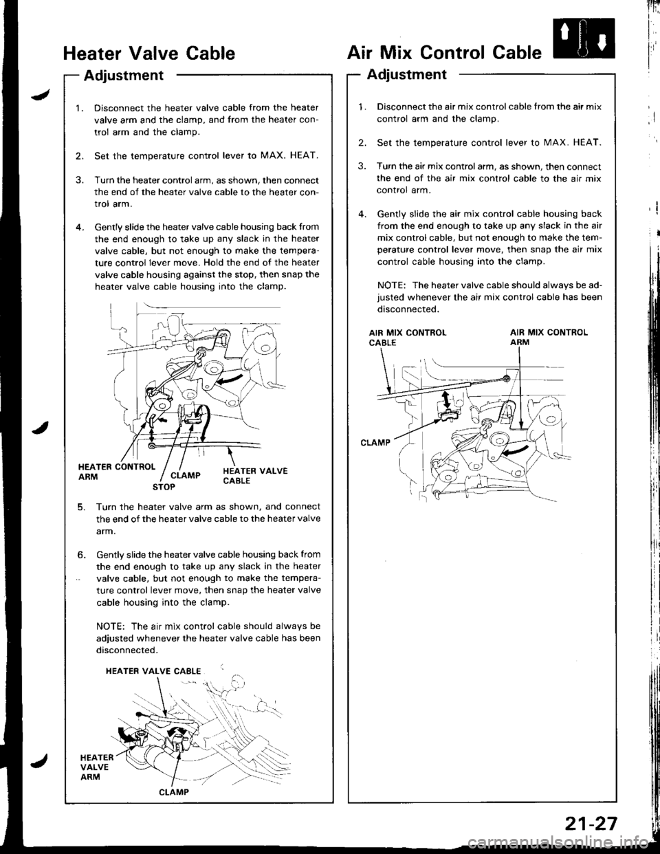
Heater Valve Cable
Adjustment
Air Mix Control Cable
Adjustment
lnri
I
I
I
I
l.Disconnect the heater valve cable from the heater
valve arm and the clamp, and from the heater con-
trol arm and the clamp.
Set the temperature control lever to MAX. HEAT.
Turn the heater control arm, as shown, then connect
the end of the heater valve cable to the heater con-
trol arm.
Gently slide the heater valve cable housing back from
the end enough to take up any slack in the heater
valve cable, but not enough to make the tempera-
ture control lever move. Hold the end of the heater
valve cable housing against the stop, then snap the
heater valve cable housing into the clamp.
HEATER CONTROLARM
HEATERVALVEARM
HEATER VALVECABLECLAMP
5. Turn th€ heater valve arm as shown, and connect
the end of the heater valve cable to the heater valve
arm.
STOP
6. Gently slide the heater valve cable housing back from
the end enough to take up any slack in the heater
valve cable, but not enough to make the tempera-
ture control lever move. then snap the heater valve
cable housing into the clamp.
NOTE: The air mix control cable should alwavs be
adjusted whenever the heater valve cable has been
disconnected.
HEATER VALVE CABLE
,i$.
CLAMP
1.Disconnect the air mix control cable from the air mix
control arm and the clamp.
Set the temperature control lever to MAX. HEAT.
Turn the air mix controlarm, as shown, then connect
the end of the air mix control cable to the air mix
control arm.
Gently slide the air mix control cable housing back
from the end enough to take up any slack in the air
mix control cable, but not enough to make the tem-
perature control lever move, then snap the air mix
control cable housing into the clamp.
NOTE: The heater valve cable should always be ad-
justed whenever the air mix control cable has been
disconnected.
2.
3.
AIR MIX CONTROLCABLEAIR MIX CONTROLARM
21-27
Page 1015 of 1681
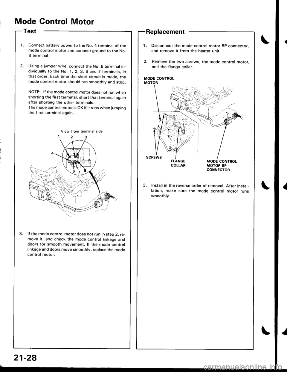
Mode Control Motor
Test
Connect battery power to the No. 4 terminal of themode control motor and connect ground to the No.
I terminal.
Using a jumper wire, connect the No. 8 termjnal in-dividually to the No. 1, 2, 3, 6 and 7 terminals, inthat order. Each time the short circuit is made. themode control motor should run smoothly and stop.
NOTE: lf the mode control motor does not run whenshorting the first terminal, short that te.minal againafter shorting the other terminals.
The mode control motor is OK if it runs when jumping
the tirst terminal again.
lf the mode control motor does nol run in steD 2, re-move it, and check the mode control linkage anddoors for smooth movement. lf the mode controllinkage and doors move smoothly, replace the mode
control motor.
Replacement
MODE CONTROLMOTOR
Disconnect the mode control motor 8P connector,
and remove it lrom the heater unit,
Remove the lwo sc.ews, the mode control motor,
and the flange collar.
MODE CONTROLMOTOR 8PCONNECTOR
Install in the reverse order of removal. After instal-lation, make sure the mode control motor runssmoothly.
21-28
Page 1017 of 1681
Relay
Test
There should be continuity between the No, I and No.3
terminals when power and ground are connected to the
No. 2 and No, 4 terminals, and there should be no conti-
nuitv when 9ower is disconnected.
rl
I
tb
I
Heater Fan Switch
Test
Check for continuity between the terminals according to
the table below.
Terminal
PositionFDBEc
OFF
o-o
2o--o
3o-o
G_o
21-30
Page 1033 of 1681
![HONDA INTEGRA 1998 4.G Workshop Manual COMPRESSOR CLUTCH RELAY P SOCIGT
I
,l
I
i:]
lll
i
ll
rl.
,i
lil
ECM CONNECTOR A (32PI
BLK/f,ED
WIRE SIDE OF FEMALE TERMINALS
ECM CONNECTOR C {31P}
BLU/RED
Connect the backprobe adapters to the stacki HONDA INTEGRA 1998 4.G Workshop Manual COMPRESSOR CLUTCH RELAY P SOCIGT
I
,l
I
i:]
lll
i
ll
rl.
,i
lil
ECM CONNECTOR A (32PI
BLK/f,ED
WIRE SIDE OF FEMALE TERMINALS
ECM CONNECTOR C {31P}
BLU/RED
Connect the backprobe adapters to the stacki](/manual-img/13/6069/w960_6069-1032.png)
COMPRESSOR CLUTCH RELAY 'P SOCIGT
I
,l
I
i:]
lll
i
ll
rl.
,i
lil
ECM CONNECTOR A (32PI
BLK/f,ED
WIRE SIDE OF FEMALE TERMINALS
ECM CONNECTOR C {31P}
BLU/RED
Connect the backprobe adapters to the stacking patch cords, and connect the cords to a mul-timeter. Using the wire insulation as a guide lor the contoured tip oI the backprobe adapter,gently slide the tip into the connector trom the wire side until it comes in contact with the ter-minalend ofthe wire {see section l1).
From page 22-14
*How to use the backprobe sets
Turn the ignition switch ON {11}.
i/leasure the voltage between theNo. 4 wire terminal (+) and bodyground {-).
Rcp.ir opon in tho BLK/YEL wirobetwsen tha undor.dash tu3a/rehy box rnd the undor.hoodfw6/i6lry box.
Turn tho ignition switch OFF, andreinstall the compressor clutch
Make suro the !y'C and heater fanswitches are OFF.
Turn the ignition switch ON {l1).
Using a *Backprobe Set (T/N
07SAZ - 001000A), measure th€voltage between the No. 17 termi-nal oI the ECM connocror A (32P)
and body ground wirh the ECMconnectors connected.
R.pair op.n in tho BLK/R€O wirobgtweon thg undor-hood fu!a/relly box 6nd th. ECM.
Using a *Backprobe Set (T/N
07SM - 001000A), moasure thevoltage betwe€n the No. 5 termi-nal of the ECM connector C (31P)
and body ground with the ECMconnectors connected.
Ropair op6n in tho BLU/RED wircbctwccn tho A/C diodc rnd theECM,
Subiiituto . known-good ECMrnd rochock. lt symptom/indicr-tion 90o3 away, .6placc the origi-n.l ECM.
WIRE SIOE OF FEMALE TERMINALS
22-15
Page 1036 of 1681
Troubleshootang
A/C System (cont'd)
8
Ftom page 22-17
Disconnect the heater controlpanel 'l4P connector.
Turn the ignition switch ON (ll).
Measure the voltage between theBLU/RED wire terminal (+) andbody ground (-).
Ropair open in the BLU/RED wirebetween the A/C thermostat andthe heater control Danel,
Turn lhe ignition switch OFF.
ls the PVC switch OKI
Disconnect the heater fan switch6P connector.
Check lor continuity in the GBNwire between the heater controlpanel and the he6ter fan switch,
Repair open in the GRN wire be-tween the hester control panel
and the heater fan switch.
Check for continuity in the BLKwire between the heater fanswitch and body ground.
Check for an ooen in the BLKwire between the hetter fanswitch and body ground. ll rhewire is OK, check for poorground at G401 and G402.
ls there continuity?
Reolace the heater fan switch.
Remove the heater control panel(see page 21-25).No.'11 BLU/RED {+)
View from wire side
View from wire side
22-1
Page 1042 of 1681
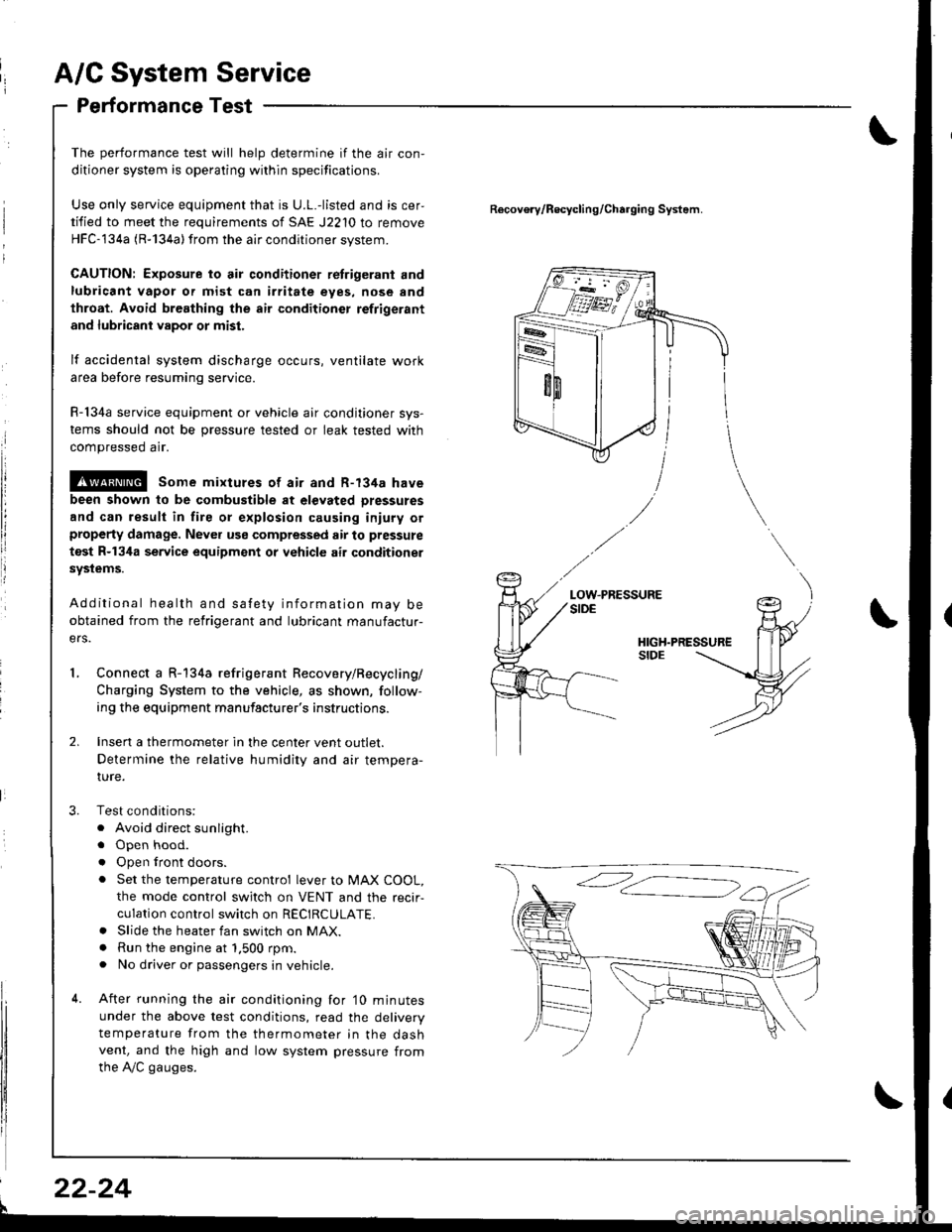
A/C System Service
Performance Test
The performance test will help determine if the air con,
ditioner system is operating within specifications.
Use only service equipment that is U.L.-listed and is cer,
tified to meet the requirements of SAE J2210 to remove
HFC-134a (R-134a) from the air conditioner svstem.
CAUTION: Exposure to air conditioner retrigerant and
lubricant vapor or mist can irritate eyes, nose and
throat. Avoid breathing the air conditioner refrigerant
and lubricant vapor or mist.
lf accidental system discharge occurs, ventilate work
area before resuming service.
R-134a service equipment or vehicle air conditioner sys-
tems should not be pressure tested or leak tested with
compressed arr.
@ some mixtures of air and R-134a have
been shown to be combustible at elevated Dressures
and can result in fire or explosion causing iniury orproperty damage. Never use compressed air to pressure
test R-134a service equipment or vehicle air conditioner
systems.
Additional health and safety information may be
obtained from the refrigerant and lubricant manufactur-
ers.
Connect a R-134a refrigerant Recovery/Recycling/
Charging System to the vehicle, as shown, follow-
ing the equipment manufacturer's instructions.
Insen a thermometer in the center vent outlet.
Determine the relative humidity and air tempera-
IUre.
Test conditions:
. Avoid direct sunlight.
. Open hood.
. Open lront doors.
. Set the temperature control lever to MAX COOL,
the mode control switch on VENT and the recir-
culation control switch on RECIRCULATE.. Slide the heater fan switch on MAX.. Run the engine at 1.500 rpm.. No driver or passengers in vehicle.
After running the air conditioning for'10 minutes
under the above test conditions, read the delivery
temperature from the thermometer in the dashvent, and the high and low system pressure from
the A,/C gauges.
Recovo.v/Recycling/Charging System.
LOW.PRESSURE
l
22-24
Page 1063 of 1681
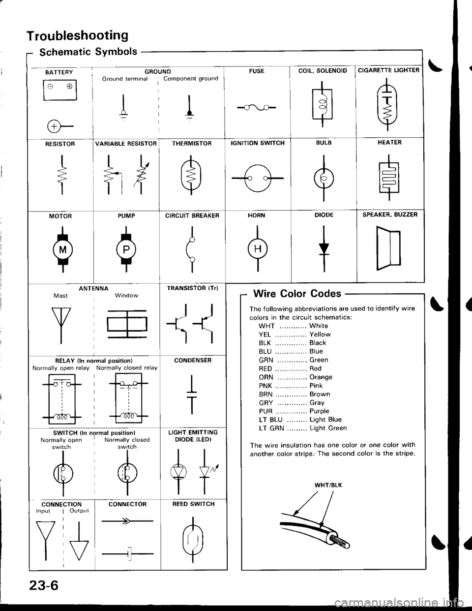
Troubleshooting
Schematic Symbolsym
BATTEBY
tr3
o-
GROUNDGround terminal Componenr ground
I il
FUSE
COIL, SOLENOID
rhtdl
l9l.|
CIGARETTE LIGHTER
,A
lrl
Y
RESISTOR
+
T
VARIABLE RESISTOR
TD
=rX
ttf
THERMISTOR
/b'
t=l
v
IGNITION SWITCH
1-\-T- l.--
BULB
A
Y
HEATER
-h
t=l
tr
MOTOR
0
PUMP
A
Y
CIRCUIT EREAKER
I
t
Y
HORN
+
DIODE
+
SPEAKER, BUZZER
D
Mast
Y
ANTtiNNA
T,
TRANSISTOR (Tr)
ll
+1^'l
)
Wire Color Codes
The following abbreviations are used to identify wire
colors in the circuit schematics:
WHT ............ White
YE1 .............. Yellow
81K .............. Black
B1U .............. Blue
GRN ............. Green
RED .............. Red
ORN ............. Orange
PNK .............. Pink
BRN .............. Brown
GRY ............. Gray
PUR .............. Purple
LT BLU ......... Light Blue
LT GRN ......... Light Green
The wire insulation has one color or one color with
another color stripe.'The second color is the stripe.
WHT/BLK
,//,aI,//t- /
R
BELAY lln noNormally open relayrmal position)
Normally closed relay
-tr-f,-
l=T= |
til
trf
CONDENSER
I
T
SWITCH {ln nrNormally openswitch
I
/6\
v
I
)rmal position)Normally closed
I
A
w
I
LIGHT EMITTINGDIODE (LEDI
AJ"
YT
CONNE
V
I
CTIONOutput
J,
CONNECTOR
+>-
l-l'l
REED SWITCH
.K
Irr ]
Y
Page 1070 of 1681
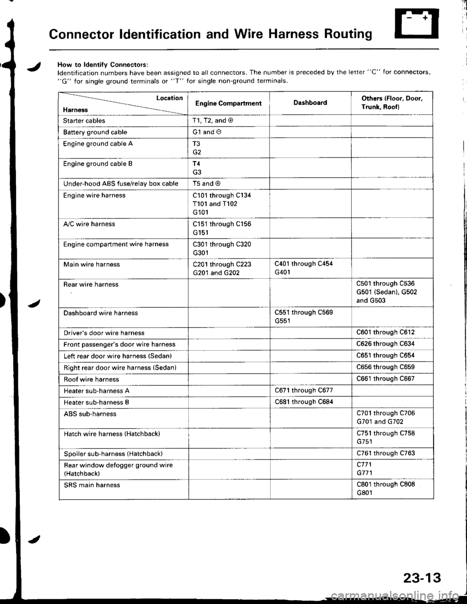
Connector ldentification and Wire Harness Routing
JHow to ldenti{v Connectors:
ldentification numbers have been assigned to all connectors. The number is preceded by the letter "C" for connectors,"G" for single ground terminals ot "f" lor single non-ground terminals.
/
Location
HarnossEngine CompartmentDashboardOthers (Floor, Door,
Trunk. Rooll
Starter cablesT1, T2, and @
Battery ground cableG1 and O
Engine ground cable A
G2
Engine ground cable BT4
G3
Under-hood ABS fuse/relav box cableT5 and @
Engine wire harnessC101 through C134
T101 and T102
G101
A,/C wire harnessC151 through C156
G151
Engine compartment wire harnessC301 through C320
G301
Main wire harnessC201 through C223
G20'l and G202
C40l through C454
G401
Rear wire harnessC501 through C536
G501 (Sedan), G502
and G503
Dashboard wire harnessC551 through C569
G551
Driver's door wire harnessC601 through C612
Front passenger's door wire harnessC626 through C634
Left rear door wire harness (Sedan)C65l through C654
Right rear door wire harness (SedanlC656 throughc659
Roof wire harnessC661 through C667
Heater sub-harness AC671 through C677
Heater sub-harness BC68l through C684
ABS sub-harnessC701 through C706
G701 and G702
Hatch wire harness (Hatchback)C751 through C758
Spoiler sub-harness {Hatchback)C761 through C763
Rear window defogger ground wire
(Hatchback)
c11 l
G77'l
SRS main harnessC801 through C808
G801
23-13