1998 HONDA INTEGRA transmission oil
[x] Cancel search: transmission oilPage 1600 of 1681
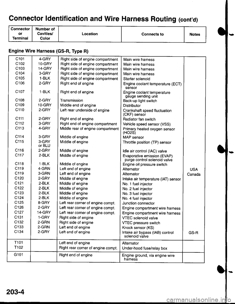
Connector ldentification and Wire Harness Routing (conrd)
Connector
ol
Terminal
Number of
Cavities/
Golor
LocationConnects toNotes
Engine Wire Harness (GS-R, Type R)
c101
c102
c103
c104
U IUC
c106
c107
c108
c109
c110
c111
c112
c113
c114
c115
c116
c117
c118
c11 9
c119
c120
c121
cl22
c123
vtzl
wt10
c127
c131
c132
c133
c134
4-GRY
1O-GRY'I4-GRY
3-GRY
1 -BLK
2-GRY
1.BLK
2-GRY
1O-GRY
2-GRY
2-GRY
3-GRY
4-GRY
3-GRY
3.GRY
or BLU
2-GRY
2-BLK
1 -BLK
4-GRN
3-GRN
2.GRY
2-BLK
2-BLK
2-BLK
2-BLK
8-GRY
2.GRY
14-GRY
1-GRY
2-GRN
2-GRN
2-GRY
Right side of engine compartment
Right side of engine compartment
Bight side of engine compartment
Right side of engine compartment
Right side of engine compartment
Right end of engine
Right end of engine
Transmission
Middle end of engine
Left rear underside of engine
Right end of engine
Right end of engine compartment
Middle rear of engine compartment
Middle of engine
Middle of engine
Middle of engine
Middle of engine
Middle of engine
Left end of engine
Left end of engine
Middle of engine
Middle of engine
Middle of engine
Middle of engine
Middle of engine
Left rear corner of engine compt.
Left rear corner of engine compt.
Left rear corner of engine compt.
Right side of engine
Right side of engine
Left end of engine
Left end of engine
Main wire harness
Main wire harness
Main wire harness
Main wire harness
Starter solenoid
Engine coolant temperature (ECT)
sensor
Engine coolant temperaturegauge sending unit
Back-up light switch
Distributor
Crankshaft speed f luctuation(CKF) sensor
Radiator fan switch
Vehicle speed sensor (VSS)
Primarv heated oxvoen sensor(Hozs)
MAP sensor
Throttle position (TP) sensor
ldle air control (lAC) valve
Evaporative emission (EVAP)purge control solenoid valve
Engine oil pressure switch
Alternator
Alternator
Intake air temperature (lAT) sensor
No. 1 fuel injector
No. 2 fuel injector
No. 3 fuel injector
No. 4 fuel injector
Junction connector
Engine compartment wire harness
Engine compartment wire harness
VTEC solenoid valve
VTEC pressure switch
Knock sensor (KS)
Intake air bypass (lAB) controlsolenoid valve
USA
Canada
GS.R
T101
r102
Left end of engine
Right rear corner of engine compt.
Alternator
Under-hood fuse/relay box
G101Right end of engineEngine ground, via engine wirenarness
203-4
Page 1632 of 1681
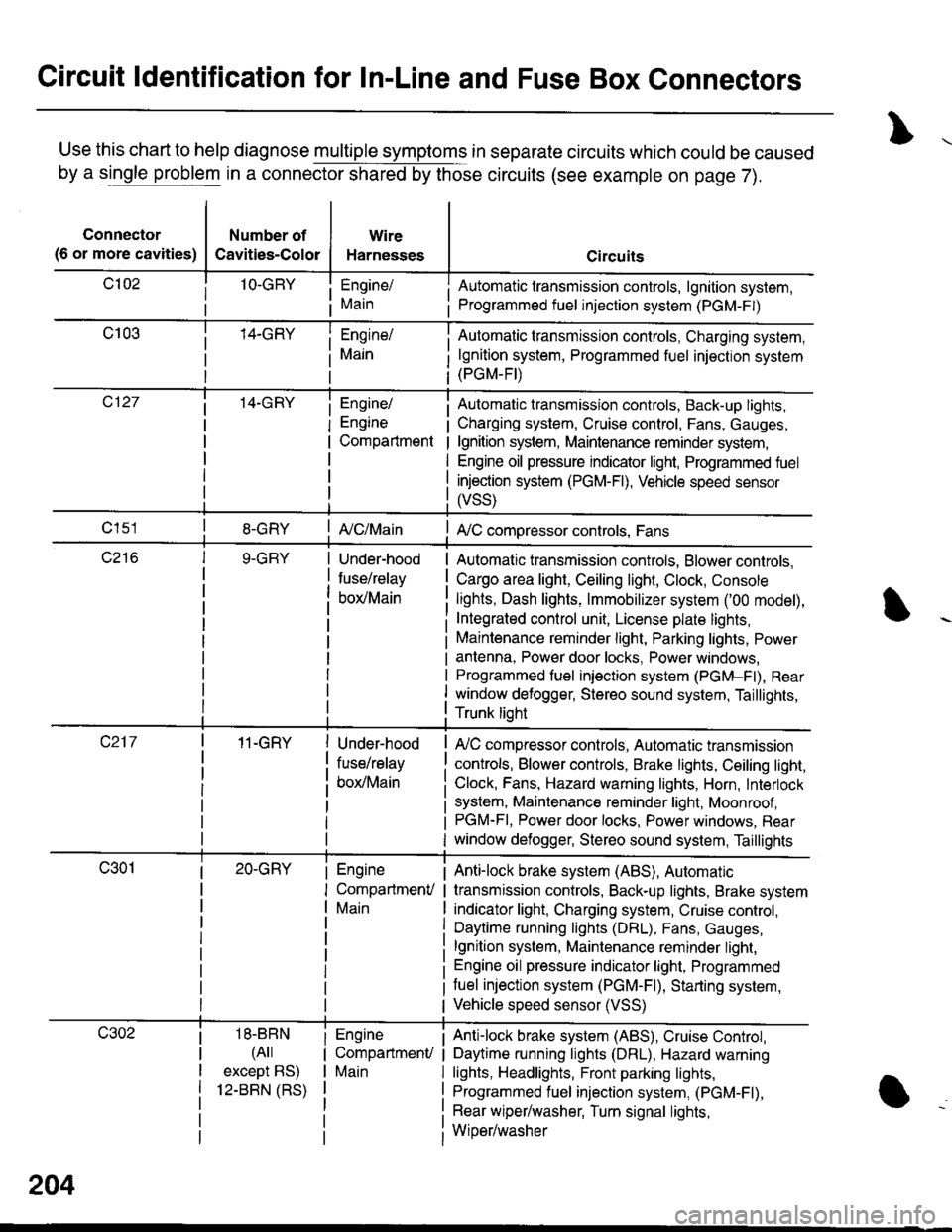
Circuit ldentification for In-Line and Fuse Box Connectors
Use this chart to help diagnose multiple symptoms in separate circuits which could be caused
by a single problem in a connector shared by those circuits (see example on page 7).
Connector
(6 or more cavities)
Number of
Cavities-Color
Wire
Harnesses
Engine/
Main
Engine/
Engine
Compartment
I Automatic transmission controls, lgnition system,
i Programmed fuel injection system (PGM-F|)
Automatic transmission controls, Charging system,
lgnition system, Programmed fuel injection system(PGM-FI)
Automatic transmission controls, Back-up lights,
Charging system, Cruise control, Fans, Gauges,
lgnition system, Maintenance reminder system,
Engine oil pressure indicator light, Programmed fuel
injection system (PGM-Fl), Vehicle speed sensor
ffss)
| {c/Main! A,/C compressor controls, Fans
Under-hood
fuse/relay
box/Main
Automatic transmission controls, Blower controls,
Cargo area light, Ceiling light, Clock, Console
lights, Dash lights, lmmobilizer system ('00 model),
Integrated control unit, License plate lights,
Maintenance reminder light, Parking lights, Power
antenna, Power door locks, Power windows,
Programmed fuel iniection system (PGM-Fl), Rear
window defogger, Stereo sound system, Taillights,
Trunk lioht
11-GRY
18-BBN
(4il
except BS)
12-BBN (RS)
Under-hood
fuse/relay
box/Main
Engine
CompartmenV
Main
Engine
CompartmenU
Main
lr,/C compressor controls, Automatic transmission
controls, Blower controls, Brake lights, Ceiling light,
Clock, Fans, Hazard warning lights, Horn, Interlock
system, Maintenance reminder light, Moonroof ,PGM-FI, Power door locks, Power windows, Rear
window defogger, Stereo sound system, Taillights
Anti-lock brake system (ABS), Automatic
transmission controls, Back-up lights, Brake system
indicator light, Charging system, Cruise control,
Daytime running lights (DRL), Fans, Gauges,
lgnition system, Maintenance reminder light,
Engine oil pressure indicator light, Programmed
tuel injection system (PGM-F|), Starting system,
Vehicle speed sensor (VSS)
Anti-lock brake system (ABS), Cruise Conkol,
Daytime running lights (DRL), Hazard warning
lights, Headlights, Front parking lights,
Programmed fuel injection system, (PGM-Fl),
Rear wiper/washer, Turn signal lights,
Wiper/washer
204
Page 1642 of 1681
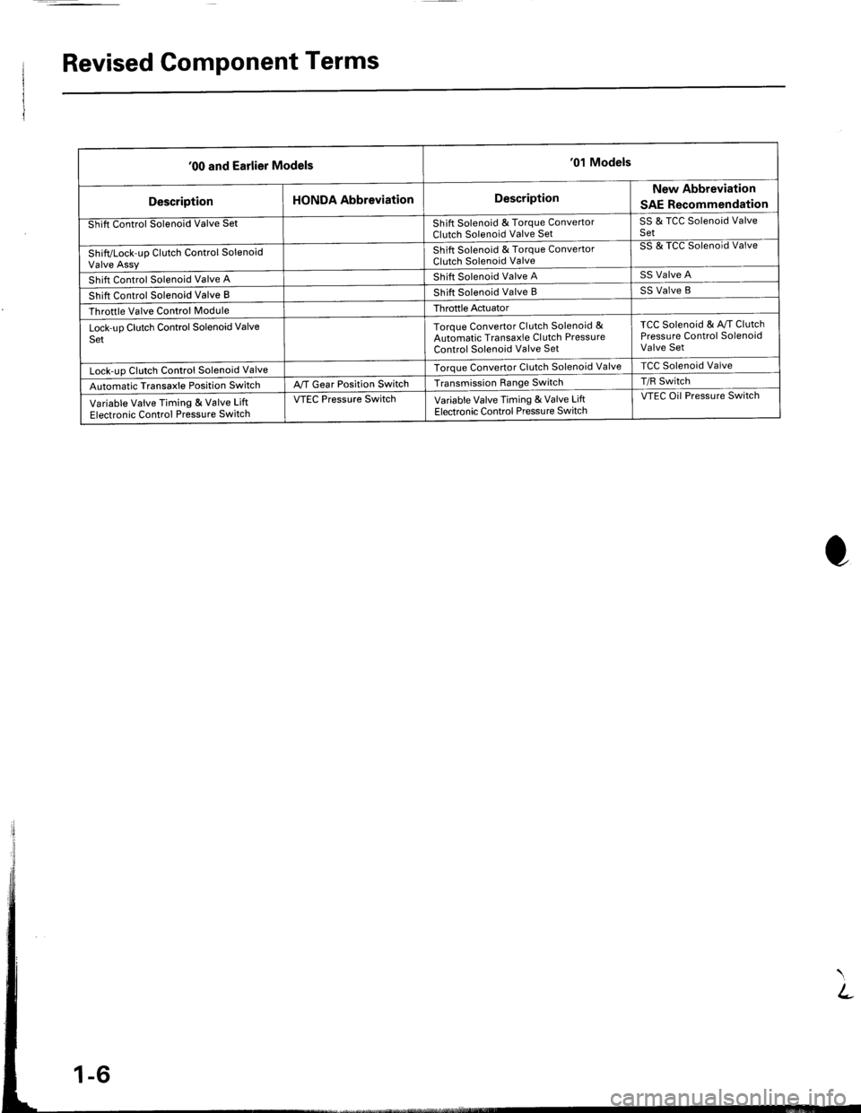
Revised Component Terms
'00 and Earlier Models'01 Models
DescriptionHONDA AbbreviationDescriptionNew Abbreviation
SAE Recommendation
Shift Control Solenoid Valve SetShift Solenoid & Torque ConvertorClutch Solenoid Valve SetSS & TCC Solenoid ValveSet
Shift/Lock-up Clutch Control SolenoidValve Assy
Shift Solenoid & Torque ConvertorClutch Solenoid Valve
SS & TCC Solenoid Valve
Shift Control Solenoid Valve AShift Solenoid Valve ASS Valve A
Shift Control Solenoid Valve BShift Solenoid Valve BSS Valve B
Throttle Valve Control ModuleThroftle Actuator
Lock-uo Clutch Control Solenoid ValveSetToroue Convertor Clutch Solenoid &Automatic Transaxle Cl utch PressureControl Solenoid Valve Set
TCC Solenoid & Av/T ClutchPressure Control SolenoidValve Set
Lock-uo Clutch Control Solenoid ValveTorque Convertor Clutch Solenoid ValveTCC Solenoid Valve
Automatic Transaxle Position SwitchA,/T Gear Position SwitchTransmission Range SwitchT/R Switch
Variable Valve Timing & Valve LiftElectronic Control Pressure Switch
VTEC Pressure SwitchVariable Valve Timing & Valve LiftElectronic Control Pressu re Switch
VTEC Oil Pressure Switch
Page 1649 of 1681
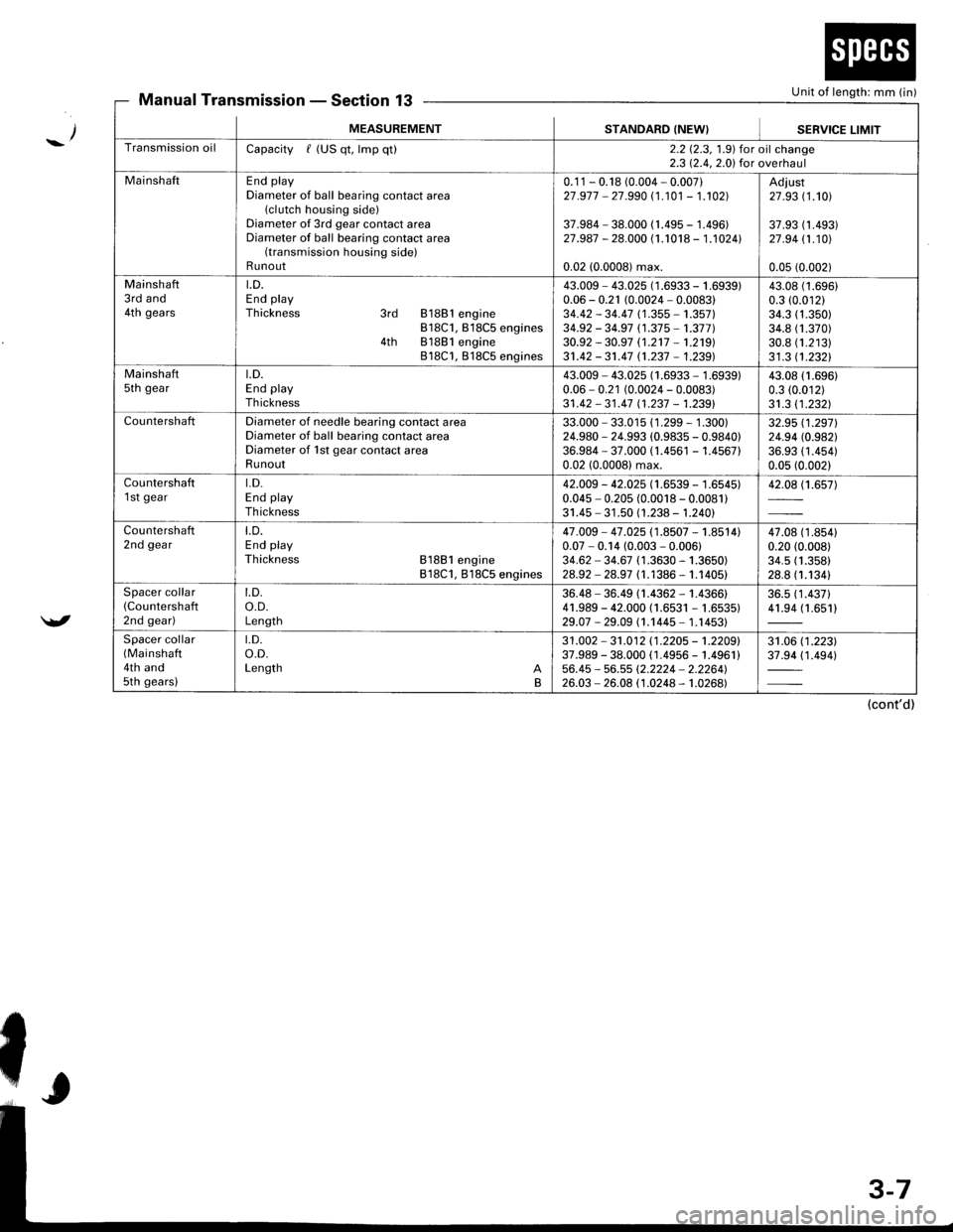
Unit of length: mm (in)Manual TransmissionSection 13
_/
/
MEASUREMENTSTANDARD (NEW}SEBVICE LIMIT
Transmission oilCapacity / (US qt, lmp qt)2.2 12.3, 1.9) for oil change2.3 12.4,2.0) for overhaul
MainshaftEnd playDiameter of ball bearing contact area(clutch housing side)Diameter of 3rd gear contact areaDiameter of ball bearing contact area(transmission housing side)Runout
0.1 1 - 0.18 (0.004 - 0.007)27 .977 - 27.990 (1 .101 - 1.102]|
37.984 - 38.000 (1.495 - 1.496)27.987 - 28.000 (1.1018 - 1.1024l.
0.02 (0.0008) max.
Adiust27 .93 (1.101
37.93 (1 .493)27 .94 11.101
0.05 (0.002)
Mainshaft3rd and4th gears
LD.End playThickness 3rd 81881 engine818C1, B18C5 engines4th 81881 engine818C1, 818C5 engines
43.009 - 43.025 (1 .6933 - 1 .(0.06 - 0.21 (0.0024 - 0.0083)34.42 - 34.47 (1 .355 - 1.357)34.92 - 34.97 (1.37 5 -'�t.377 )30.92 - 30.97 (1.2't7 -'�t.219)
31.42 - 31.47 n.237 - 1.239)
i939)43.0t0.3 ((
34.334.830.831 .3
(1.696)
.01211.350)1.370)1.21311.2321
Mainshaftsth geart.D.End playTh ickness
43.009 - 43.025 (1.6933 - 1.6939)0.06 - 0.21 (0.0024 - 0.0083)31 .42 - 31 .47 11 .237 - 1.2391
43.08 (1.696)
0.3 (0.012)
31.3 11.2321
CountershaftDiameter of needle bearing contact areaDiameter of ball bearing contact areaDiameter of 1st gear contact areaRunout
33.000 - 33.015 (1 .299 - 1 .300)24.980 - 24.993 (0.9835 - 0.9840)36.984 - 37.000 (1.4561 - 1.456710.02 (0.0008) max.
32.95 (1.2971
24.94 (0.982)
36.93 (1 .454)0.05 (0.002)
Countershaft1 st geart.D.End playTh ickness
42.009 - 42.025 (1.6539 - 1.6545)0.045 - 0.205 (0.0018 - 0.0081)31.45 - 31 .50 (1.238 - 1.240)
42.08 (1.657)
Countershaft2nd geart.D.End playThickness 81881 engine818C1, 818C5 engines
47.009 - 47 .025 (1.8507 - 1.8514)0.07 - 0.14 (0.003 - 0.006)34.62 - 34.67 (1 .3630 - 1.3650)28.92 - 28.97 (1.1386 - 1.1405)
47.08 (1 .8s410.20 (0.008)
34.5 (1.358)
28.8 (1.1341
Spacer collar(Countershafl
2nd gear)
t.D.o.D.Length
36.48 - 36.49 (1.4362 - 1.4366)41.989 - 42.000 (1.6531 - 1.6535)29.07 -29.09 (1.1445- 1.14531
36.5 (1 .437)41.94 (1.651)
Spacer collar(Mainshaft
4th and5th gears)
t.D.o.D.Length AB
31 .002 - 31 .012 11 .2205 - 't .2209'37.989 - 38.000 ( 1.4956 - 1.4961 )56.45 - 56.55 (2.2224 - 2.2264'�)26.03 - 26.08 (1.0248 - 1.0268)
31.06 (1 .223)37.94 (1 .494)
(cont'd)
Page 1654 of 1681
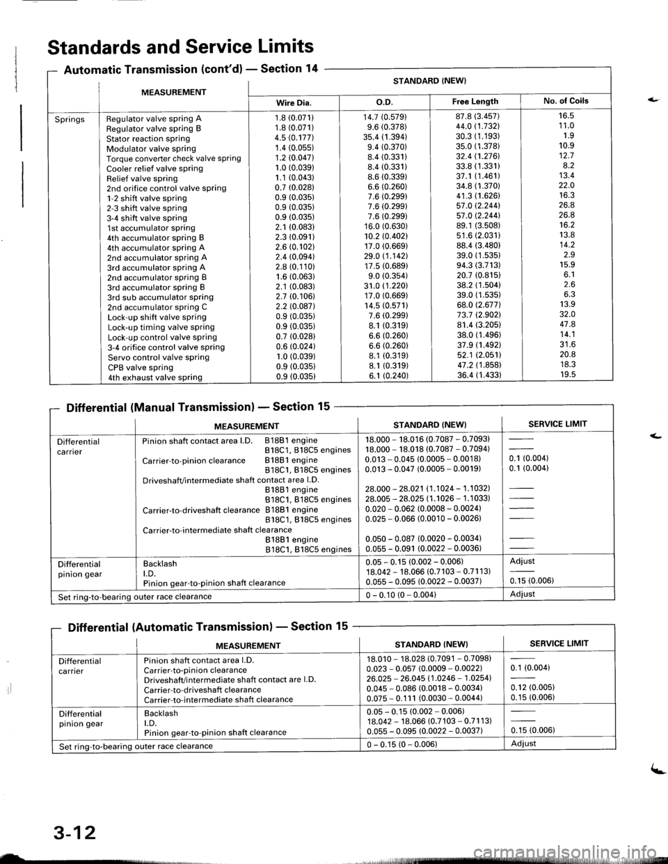
MFASIIREMENTSTANDARD (NEW}
Wire Dia.o.D.Free LengthNo. of Goils
SpringsRegulator valve spring ARegulator valve spring BStator reaction sPringModulator valve springTorque converter check valve springCooler relief valve springRelief valve spring2nd orifice control valve spring1-2 shift valve spring2-3 shift valve spring3-4 shift valve spring1st accumulator spring4th accumulator spring B4th accumulator spring A2nd accumulator spring A3rd accumulator spring A2nd accumulator spring B3rd accumulator spring B3rd sub accumulator spring2nd accumulator spring CLock-up shift valve springLock-up timing valve springLock-up control valve spring3-4 orifice control valve springServo control valve springCPB valve spring4th exhaust valve spring
1.8 (0.071)
1.8 (0.071)
4.5 rc.177].1.4 (0.05s)
1.2 10.047l.1.0 (0.039)
1.1 (0.043)
0.7 (0.0281
0.9 (0.035)
0.9 (0.035)
0.9 (0.035)
2.1 (0.083)
2.3 (0.091)
2.6 (0.102)
2.4 (0.094)
2.8 (0.110)
1.6 (0.063)
2.1 (0.083)
2.7 (0.106)
2.2 l0.o87l0.9 (0.035)
0.9 (0.035)
0.7 (0.028)
0.6 (0.024)
1.0 (0.039)
0.9 (0.0351
0.9 (0.035)
14.7 (0.5791
9.6 (0.378)
35.4 (1 .394)9.4 (0.370)
8.4 (0.331)
8.4 (0.331)
8.6 (0.339)
6.6 (0.260)
7.6 (0.299)
7.6 (0.299)
7.6 (0.299)
16.0 (0.630)
10.2 rc.402117.0 (0.669)
29.0 11.142117.5 (0.689)
9.0 (0.354)
31.0 (1 .220)17.0 (0.669)
14.5 (0.571)
7.6 (0.299)
8.1 (0.319)
6.6 (0.260)
6.6 (0.260)
8.1 (0.319)
8.1 (0.319)
6.1 (0.240)
87.8 (3.457)
44.0 (1.732\
30.3 (1.193)
35.0 (1.378)
32.4 (1.2761.
33.8 (1.331)
37.1 (1.461)
34.8 (1.370)
41.3 (1.626)
57.0 12.244157.0 12.244].89.1 (3.508)
s1.6 (2.0311
88.4 (3.480)
39.0 (1 .53s)94.3 (3.713)
20.7 (0.815)
38.2 (1.504)
39.0 (1.535)
68.0 (2.677)
73.7 (2.9021
81.4 (3.205)
38.0 (1.496)
37.9 (1.492)
52.1 (2.0511
47.2 (1 .858)36.4 (1.433)
16.51 1.01.910.912.78.213.422.01A ?
26.826.8't6.2
13.814.2z.J15.9o. l2.66.313.932.O47.814.1?1 A
20.8ttJ.JI v.5
Standards and Service Limits
Automatic Transmission (cont'd) - Section 14
Differential (Manual Transmission) - Section 15
Differential (Automatic Transmission) - Section 15
ilt5stlrrr, - 4,
MEASUREMENTSTANDARD (NEW}SERVICE LIMIT
Differentialca rnerPinion shaft contact area l.D. 81881 engineB18C1, 818C5 engines
Carrier-to-pinionclearance Bl88lengine818C1, 818C5 enginesDriveshafVintermediate shaft contact area l.D.81881 engine818C1. 818C5 engines
Carrier-to-driveshaft clearance 81881 engine818C1, 818C5 engines
Carrier-to-intermediate shaft clea rance81881 engine818C1, 818C5 engines
18.000 - 18.016 (0.7087 - 0.7093)18.000 - 18.018 (0.7087 - 0.7094)0.013 - 0.045 (0.0005 - 0.0018)0.013 - 0.047 (0.0005 - 0.0019)
28.000 - 28.021 11.1024 - 1.1032].28.005 - 28.025 l1 .'�t026 - 1 .1 033)
0.020 - 0.062 (0.0008 - 0.0024)0.025 - 0.066 (0.0010 - 0.00261
0.050 - 0.087 (0.0020 - 0.0034)0.055 - 0.091 (0.0022 - 0.0036)
- toooot0.1 (0.004)
Differentialpinion gearBacklasht.D.Pinion gear-to-pinion shaft clearance
0.05 - 0.15 (0.002 - 0.006)18.042 - 18.066 (0.7103 - 0.71 1 3)0.055 - 0.095 (0.0022 - 0.0037)
Adjust
0.15 (0.006)
Set ring-to-bearing)uter race clearance0 - 0.10 (0 - 0.004)Adjust
nsmlssaonl - Sectton
MEASUREMENTSERVICE LIMITSTANDARD (NEW}
Differentialca rrierPinion shaft contact area l.D.Carrier-to-pinion clearanceDriveshaft/i ntermediate shaft contact are l.D.
Carrier-to-driveshaft clearanceCarrier-to-intermediate shaft clearance
18.010 - 18.028 (0.7091 - 0.7098)0.023 - 0.057 (0.0009 - 0.0022)26.025 - 26.045 11.0246 - 1.02541
0.045 - 0.086 (0.0018 - 0.0034)0.075 - 0.1 11 (0.0030 - 0.0044)
0.1 (0.004)
0.12 (0.005)
0.15 (0.006)
Differentialpinion gearBacklasht.D.Pinion gear-to-pinion shaft clearance
0.05 - 0.15 (0.002 - 0.006)18.042 - 18.066 (0.7 103 - 0.71 1 3)0.055 - 0.095 (0.0022 - 0.0037)0.15 (0.006)
Set ring-to-bearing outer race clearance0 - 0.15 (0 - 0.006)Adiust
uL-
3-12
(-
Page 1657 of 1681
{b
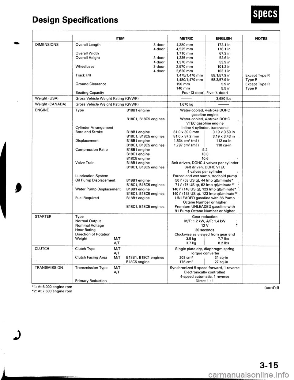
Design Specifications
x1: At 6,000 engine rpm*2: At 7,600 engine rpm
0
(cont'd)
{
ITEMMETRICENGLISHNOTES
DIMENSIONSOverall Length 3-door4-doorOverall WidthOverall Height 3-door4-doorWheelbase 3-door4-doorTrack F/R
Ground Clearance
Seating Capacity
4,380 mm4,525 mm1,710 mm1,335 mm ]1,370 mm ]2,57O mm2,62O mm 11 ,415/1,470 mm I1,480/1,470 mm I1s0 mm I140 mm IFour (3-door),
172.4 in178.1 in67.3 in52.6 in53.9 in101.2 in103.1 in58.1/57.9 in58.3/57.9 in5.9 in5.5 tnFive (4-door)
Except Type RType RExcept Type RType R
weisht (usA)Gross Vehicle Weight Rating (GVWR)3.680 rbs
Weight (CANADA)Gross Vehicle Weight Rating (GVWR)1,670 kg
ENGINEType
Cylinder ArrangementBore and Stroke
Displacement
Compression Ratio
Valve Train
Lubrication SystemOil Pump Displacement
Water Pump Displacemenl
Fuel Required
8188l engine
818C1, Bl8C5 engines
81881 engine818C1, 818C5 engines81881 engine818C1, B18C5 engines81881 engine818C1 engine818C5 engineB1881 engine818C1, B18C5 engines
81881 engine818C1, B18CS enginesB1881 engine818C1, 818C5 enginesB1881 engine
818C1,818C5 engines
Water-cooled. 4-stroke DOHCgasoline engineWater-cooled, 4-stroke DOHCVTEC gasoline engineInline 4-cylinder, transverse81.0 x 89.0 mm | 3.19 x 3.50 in81.0 x 87.2 mm | 3.19 x 3.43 in1,834 cm3 (m/ ) | 112 cu-in1,797 cm3 (m/ ) | 110 cu-in9.210.010.6Belt driven, DOHC 4 valves per cylinderBelt driven, DOHC VTEC4 valves per cylinderForced and wet sump, trochoid pump50 f (53 US qt, 44 lmp qt)/minute*'71 ( (75 US qt,62 lmp qt)/minute*'� :
140 I 1148 US qt. 123 lmp qtl/minute*1140 t (148 US qt, 123 lmp qt)/minute*2UNLEADED gasoline with 86 PumpOctane Number or higherPremium UNLEADED gasoline with91 Pump Octane Number or higher
STARTERTypeNormal OutputNominal VoltageHour RatingDirection of RotationWeight MffAIT
Gear reductionMfi:1.2 kW, A,/T: 1.4 kW12V ,
30 secondsClockwise as viewed from gear end3.5 ks | 7.7 lbs3.7 kg | 8.2 lbs
CLUTCHClutch Type
Clutch Facing Area
M/TAfiM/T 81881, 818C1 engines818C5 engine
Single plate dry, diaphragm springTorque converter203 cm2 , 31 sq-in176 cm2 | 27 sq-in
TRANSMISSIONTransmission Type
Primary Reduction
M/TAITSynchronized S-speed forward, 1 reverseElectronical ly control led4-speed automatic, 1 reverseDirect 1 : 1
3-15
Page 1658 of 1681
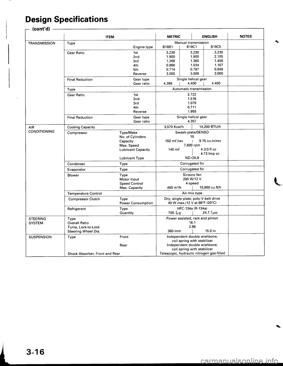
ITEMMETRICIENGLISHINOTES
TRANSMISSIONTypeEngine typeManual transmissionB18B1lB18C1lB18C5
Gear Ratio1st2nd3rd4th5thReverse
3.230't.900
1.2690.9660.7143.000
3.2301.9001.3601.0340.7873.000
3.2302.1051.4581.1070.8483.000
Final Reduction Gear typeGear ratioSingle helical gear4.266 14.400 14.400
TypeAutomatic transmission
Gear Ratio 1st2nd3rd4thReverse
2.722't.516
1.0790.7111.955
Final Reduction GeartypeGear ratioSingle helical gear4.357
AIRCONDITIONINGCooling Capacity3.570 Kcar/h | 14,200 BTU/h
Compressor Type/MakeNo. of CylindersCapacityMax. SpeedLubricant Capacity
Lubricant Type
Swash-plate/DENSO10150 m//rev | 9.15 cu-in/rev7,600 rpm140 m/ | 4-213 fl oz
I c.z3 |rp o.ND.OILS
Condenser TypeCorrugated fin
Evaporator TypeCorrugated fin
Blower TypeMotor InputSpeed ControlMax. Capacity
Sirocco fan200w1't2v4-speed450 m3/h | 15,900 cu fVh
Temperature ControlAir-mix type
Compressor Clutch TypePower ConsumptionDry. single plate, poly-V-belt drive40W max.l12 V at 68'F (20'C)
Refrigerant TypeQuantityHFC-134a (R-134a)
700_309 | 24.7_?.aoz
STEERINGSYSTEMTypeOverall RatioTurns, Lock-to-LockSteering Wheel Dia.
Power assisted, rack and pinion16.12.98380 mm | 15.0 in
SUSPENSIONType Front
Rear
Shock Absorber, Front and Rear
Independent double wishbone,coil spring with stabilizerIndependent double wishbone,coil spring with stabilizerTelescopic, hydraulic nitrogen gas-filled
Design Specifications
(cont'd)
L
\
Page 1664 of 1681
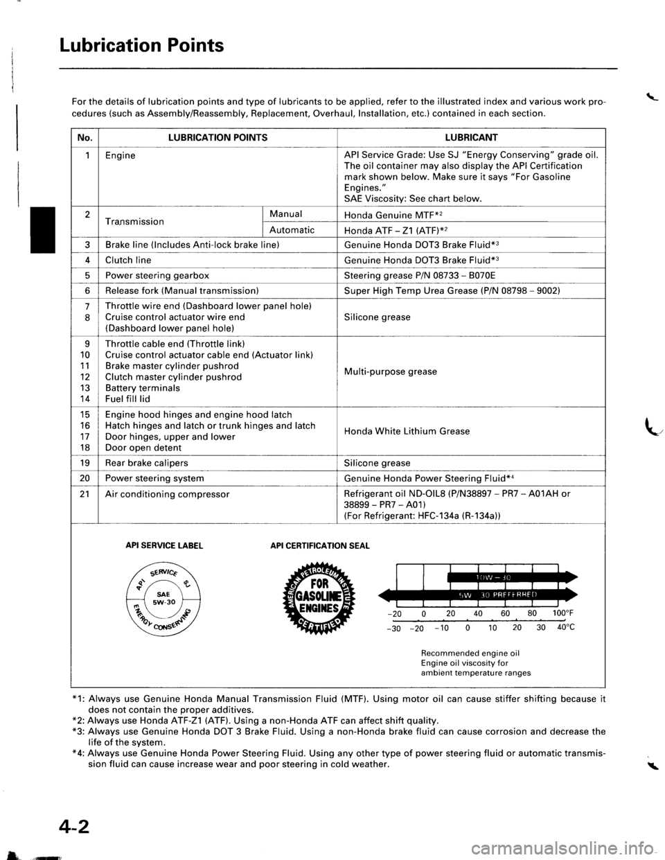
Lubrication Points
\_For the details of lubrication points and type of lubricants to be applied, refer to the illustrated index and various work pro-
cedures (such as Assembly/Reassembly, Replacement, Overhaul, Installation, etc.) contained in each section.
*1: Always use Genuine Honda Manual Transmission Fluid (MTF). Using motor oil can cause stiffer shifting because it
does not contain the proper additives.*2: Always use Honda ATF-Z1 (ATF). Using a non-Honda ATF can affect shift quality.*3: Always use Genuine Honda DOT 3 Brake Fluid. Using a non-Honda brake fluid can cause corrosion and decrease thelife of the system.*4: Always use Genuine Honda Power Steering Fluid. Using any other type of power steering fluid or automatic transmis-sion fluid can cause increase wear and poor steering in cold weather.i
4-2
5 ffi
No.LUBRICATION POINTSLUBRICANT
1EngineAPI Service Grade: Use SJ "Energy Conserving" grade oil.The oil container may also display the API Certificationmark shown below. Make sure it says "For GasolineEngines."
SAE Viscosity: See chart below.
2Tra.nsmissionManualHonda Genuine MTF*2
AutomaticHonda ATF -21 (ATFY2
3Brake line (lncludes Anti-lock brake line)Genuine Honda DOT3 Brake Fluid*3
4Clutch lineGenuine Honda DOT3 Brake Fluid*3
5Power steering gearboxSteering grease P/N 08733 - 8070E
6Release fork (Manual transmission)Super High Temp Urea Grease (P/N 08798 - 9002)
.J
Throttle wire end (Dashboard lower panel hole)
Cruise control actuator wire end(Dashboard lower panel hole)
Silicone grease
q
10
11
12
13
14
Throttle cable end (Throttle link)
Cruise control actuator cable end (Actuator link)Brake master cylinder pushrod
Clutch master cylinder pushrod
Battery terminalsFuel fill lid
Multi-purpose grease
tc
16
17
18
Engine hood hinges and engine hood latchHatch hinges and latch or trunk hinges and latch
Door hinges, upper and lower
Door open detent
Honda White Lithium Grease
19Rear brake calipersSilicone grease
20Power steering systemGenuine Honda Power Steering Fluid*a
21Air conditioning compressorRefrigerant oil ND-olL8 (P/N38897 - PR7 - A01AH or
38899-PR7-A01)(For Refrigerant: HFC-1 34a (R-1 34a))
API SERVICE TABELAPI CERTIFICATION SEAT
ZU30
Recommended engine oilEngine oil viscosity forambient temperature ranges