Page 1198 of 1681
Circuit Diagram
)
{
{
I
UNDER-HOOD FUSEiRELAY 80XIGN TIONSWITCHUNDER-DASHFUSE/RELAY BOX
. TRANSMISS]ONCONTROLMODULE (TCM)
/;; l-^--;;;;lw--BLh ---wrl f ,:+ BLK/E- t.d\o-ft\---l
I t,;:'*'
IVECM
f7
ILT GRN/BLK
YEUBLU
(n lhe gauqe assembly)D4
TRANSMISSIONCONTROLMODULErrcM)
f7
IIGRN/BLK
c6c7c8 lc9NTERLOCKCONTROLUNIT (
f7
IGRNMHT
BLK
TRANSMISSION CONTROLMODULE TICM)GRNCRN]BLULTGRNMHT
GRN/YEL
No l9 (104)FUSE
f7
IRED/BLK
A?TGEARPOSITION SWTCHRED
II
I
Y?
DASH LIGHTSBFIGHTNESSCONTROLLER
BLK
oro,G40lG20lG401
A/T GEAH POSITION NDICATOR DIMMING C RCUIT
A/T GEARPOS TIONCONSOLELIGHT(1.4w)
/ ,/ t2
{,
23-141
Page 1200 of 1681

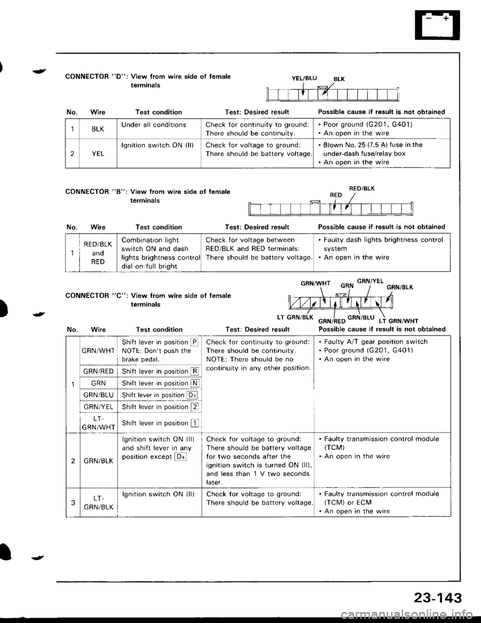
{CONNECTOR "D": View from wire side of lemale
terminalsYEL/BLU
CONNECTOR "8": View from wire side ot female
terminals
No.Wire
No.Wire
Test condition
Test condition
Test condition
Test: Desired result
Test: Desired result
Possible cause il result is not obtained
Possible cause if result is not obtained
Possible cause iI lesult is not obtained
)
CONNECTOR "C": View from wile side ot female
terminals
LT
No.Test: Desired result
1BLKUnderall conditionsCheck {or continuity to ground:
There should be continuity.
Poor ground (G201 , G401)
An open in the wire
2YEL
lgnition switch ON (ll)Check for voltage to groundl
There should be battery voltage
Blown No. 25 (7.5 A) fuse in the
under-dash fuse/relay box
An open in the wire
RED/BLK
1
R E D/BLK
ano
RED
Combination light
switch ON and dash
lights brightness control
dial on full bright
Check for voltage between
RED/BLK and RED terminalsl
There should be battery voltage.
. Faulty dash lights brightness control
system. An open in the wire
1
GRN/WHT
Shifl lever in position @NOTE: Don't push the
brake pedal.
Check {or continuity to ground:
There should be continuity.
NOTE: There should be no
continuity in any other position.
Faulty A/T gear position switch
Poor ground (G201 , G401)
An open in the wire
GRN/RED
GRN
GRN/BLU
GRN/YEL
5nrrI rever In pos[ron ll
shl, b*|' il. p"1,!lN
)nrn rever In posrron url
snt r""-. r p*;ir" tZ-
LT.
GRN/WHTShift lever in position f
2GRN/BLK
lgnition switch ON (ll)
and shift lever in any
position except E
Check for voltage to ground:
There should be battery voltage
lor two seconds after the
ignition switch is turned ON (ll),
and less than 'l V two seconds
later.
. Faulty transmission control module(TCM)
. An open in the wire
3LT-
G RN /BLK
lgnition switch ON (ll)Check lor voltage to ground:
There should be battery voltage.
. Faulty transmission control module
(TCM) or ECM'An open in the wire
23-143
Page 1209 of 1681

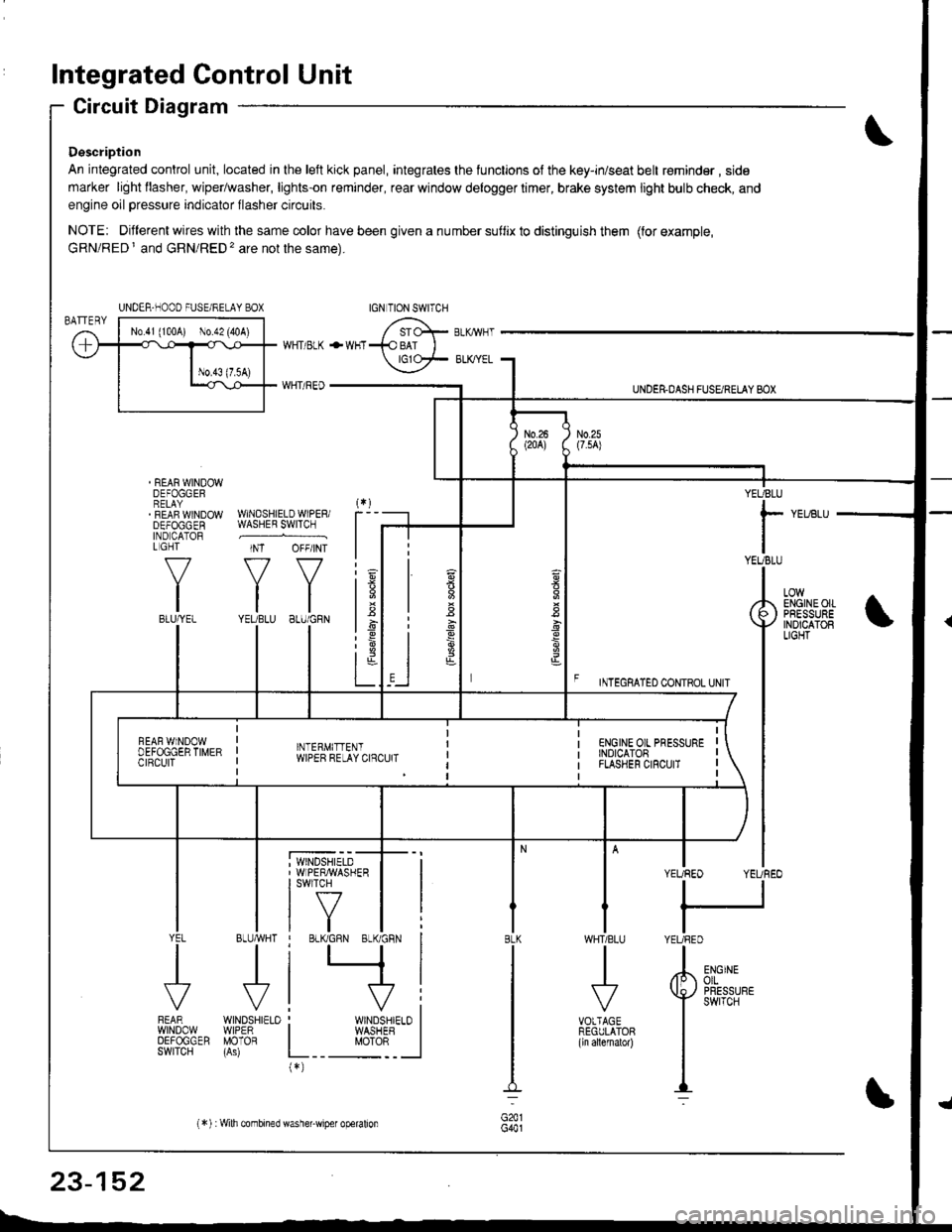
Integrated Control Unit
Circuit Diagram
Description
An integrated control unit, located in lhe left kick panel, integrates the lunctions of the key-in/seat belt r€minder , side
marker light llasher, wiper/washer, lights-on reminder, rear window delogger timer, brake system light bulb check, and
engine oil pressure indicator flasher circuits.
NOTE: Different wires with the same color have been given a nu mber suflix to distinguish them (for example,
GRN/RED I and GRN/RED'� are not the same).
REAR WINDOWDEFOGGERRELAYREAF WINDOWDEFOGGENIND CATORL GHT
f-7
IIBLU/YEL
WHT/ BLK
WHT/ REO
+WHT
WNDSHIELDWIPERiWASHER SWITCH
INT OFF/INT
f7 f7
tltlYEUBLU 8LU/GRN
BLUMHT
J
wtN0sHr€10WIPERMOTOR
UNDER.DASH FUSARETAY BOX
F rmecnlleo counoL ultr
YEUBLU
rYEUBLU
YEUREO YEUREO
tl
IYEURED
LOWENGINEOIIPRESSUREINOICATOBLIGHT
; WINDSHIELD' WIPERMASHERI swlTcH
tf7IVtlYEL
J
FEARwtN00wOEFOGGERSWITCH
WHTIBLU
J
VOTTAGEREGULATOR(ln allernatol)
BLK
G441
ENGINEolLPRESSUREswrTcH
UNDER-NOOO FUSE/RELAY BOX
1.6
:6
t;t-L
i
"'i'- 'i*-
|
I Il
I vi: WINDSHIELO II WASHEB I
L__ "oto: _ __l(*)
n
s
s
,]
23-152
(*) :Wilh combined washer-wiper operalion
Page 1217 of 1681
Lighting System
OAYTIMERESISTOR (Can.dal
Test, page 23-168
HEADLIGHTS
Component Locations Index
HIGH BEAM INDICATOR LIGHT{ln the galge assembly}Bulb Locations. page 23-122
COMAINATION LIGHT SwlTCHReplscement, page 23-168Test, page 23-162
Adjustment, page 23-170Replacement, page 23-170
CONTBOL UNIT {Can.d.)Input, Test page 23-164
23-160
Page 1218 of 1681
!/ Hatchback:
Sedan:
LICENSE PALTE LIGHTSReplacement, page 23-177
TAILLIGHT. Replacement, page 23 174. Bulb r€placement, page 23-174
LICENSE PALTE LIGHTSReplacement, page 23-177
INNER TAILI-IGHT. Replacement, page 23-175. Bulb replacement, page 23-176
. Replacement, page 23-175.8ulb replacement, page 23'176
23-161
Page 1219 of 1681
Lighting System
Circuit Diagram (USA)
R€O/BtK
I
REO/BLKIII
I
. OASH LIGHTSBFIGI.ITNESSCONTROLLER. DASH TIGHTS
RED/CRN
I
Ailsurax
Yller,l
IBL(
I
I
I-l
G201G401
. PANK NG L GNTS.TA LL GHTS. LICENSE PLATELIGHTS
UNDER.HOOD FUSE/RELAY BOX
RED]BtU
N0.21(104)No.5{10A)
III No22 I No4( lroA) ( {1oA)
IT
INo30 :(7.5A) (
I
N0.3200A)
8LK
I
G20lG40l
23-162
Page 1221 of 1681
Lighting System
Daytime Running Lights Control Unit Input Test (Ganada)
Remove the dashboard lower cover and knee bolster.
Disconnect the connectors from the daytime running
lights control unit.
Inspect the connector and socket terminals to be
sure they are all making good contact.
a lf the terminals are bent, loose or corroded. repair
them as necessary, and recheck the system.
a ll the terminals look OK. make the lollowing in-
put tests at the connector.
lf any test indicates a problem, find and cor-
rect the cause, then recheck the system.
lf all the input tests prove OK, the control unit
must be faulty; replace it.
4P CONNECTOR8P CONNECTOR
GNN/RED
WHTiRED
WHT/YEL
REO/WHTRED/GRN
YEL/BLK
23-164
View trom wire sideView from wire side
Page 1222 of 1681

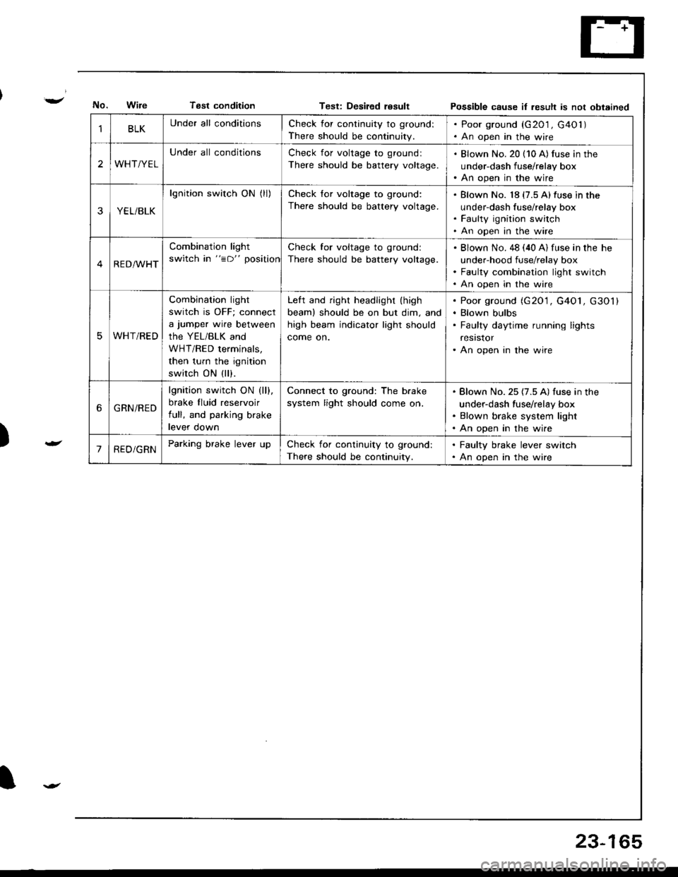
Tsst conditionTest: Desiled resultPossible cause it result is not obtained
)
BLKUnder all conditionsCheck for continuity to ground:
There should be continuity.
. Poor ground (G201 , G40l ). An open in the wire
2WHT/YEL
Under all conditionsCheck for voltage to ground:
There should be battery voltage.
. Blown No. 20 (10 A) fus€ in the
under-dash fuse/relay box. An open in the wire
YEL/BLK
lgnition switch ON (ll)Check for voltage to ground:
There should be battery voltage.
Blown No. 18 (7.5 A)fuse in the
under-dash fuse/relay box
Faulty ignition switch
An open in the wire
RED/WHT
Combination light
switch in "=D" position
Check for voltage to ground:
There should be battery voltage.
Blown No. 48 (40 A) fuse in the he
under-hood fuse/relay box
Faulty combination light switch
An open in the wire
WHT/RED
Combination light
switch is OFF; connect
a jumper wire between
the YEL/BLK and
WHT/RED terminals,
then turn the ignition
switch ON (ll).
Left and right headlight (high
beaml should be on but dim, and
high beam indicator light should
come on.
Poor ground (G20'1, G4O1, G301)
Blown bulbs
Faulty daytime running lights
resrstor
An open in the wire
6GRN/RED
lgnition switch ON (ll).
brake fluid reservoir
full, and parking brake
levef oown
Connect to ground: The b.ake
system light should come on.
Blown No. 25 (7.5 A) fuse in the
under-dash fuse/relay box
Blown brake system light
An open in the wire
'1RED/GRNParking brake lever upCheck for continuity to ground:
There should be continuity.
. Faulty brake lever switch. An open in the wire
23-165