Page 1105 of 1681
![HONDA INTEGRA 1998 4.G Workshop Manual Fuses
Under-dash Fuse/Relay Box
C920 [To SRS msin harnc$ lc8{,l}lC922 [To ignition rwitchl
C923lTo main wir. harn6! (Cil,alll
C€24 [To m.in wiro hrrno$ lc,l,l2]l
lTo pow.r windowrclayl
CgNlS Oo turn HONDA INTEGRA 1998 4.G Workshop Manual Fuses
Under-dash Fuse/Relay Box
C920 [To SRS msin harnc$ lc8{,l}lC922 [To ignition rwitchl
C923lTo main wir. harn6! (Cil,alll
C€24 [To m.in wiro hrrno$ lc,l,l2]l
lTo pow.r windowrclayl
CgNlS Oo turn](/manual-img/13/6069/w960_6069-1104.png)
Fuses
Under-dash Fuse/Relay Box
C920 [To SRS msin harnc$ lc8{,l}lC922 [To ignition rwitchl
C923lTo main wir. harn6! (Cil,alll
C€24 [To m.in wiro hrrno$ lc,l,l2]l
lTo pow.r windowrclayl
CgNlS Oo turn 3ign.l/h.z.rd rcl.yl
C919 [To root wir. hsmolr {C661ll
al Spare fusel: Option connector (+B)
2: Option conn€ctor (oash lights)3: Option connector (ACC)
4: Option connector {lG2}*: Not us€d
Fusa Number Amp!wire Color
C928 [To r..] window d.toggd r.l.yl
Compon€nt(s) or Circuit(3) Protaqtad
C92l ITo d..hbo.rd wir. h.rness lc551ll
- r-t r-'l r-'t n n r-'t n n r-1 r-'l r-l4 2321 2s 26 27 28 29 30 3t 32 33IJ IJ IJ LI LI IJ LI LJ IJ LI LJ I.J
- r-t n n r-l r-'t r-t r-'l r-1 n r-'t r-1a 12 13 14 15 t6 17 ,t8 19 20 21 22I-J LI IJ IJ tJ LI LI IJ IJ IJ LI IJ
- r-'t |;l n r-1 n |;t r-'t r-t r-1 n r-'ta 12 3 it 5 67 8 910 11
LI IJ IJ IJ LI IJ LI LI I-J LI LJ LI
1204WHT/GRNPower door lock control unit
Not used
10AGRN,4/VHTRear window washer motor
GRN/BLKRear window wioer motor
410 ARED/BLURight headlight (high beam)
10ARED/GRNLeft headlight (high beam), high beam indicator light
Not used
720A.GRN/BLKLeft rear power window motor
a204YEUBLKRight rear power window motor
15 ABLK/YELlgnition coil
10204BLU/BLKPasseflger's power window motor
l1204WHTI/ELPower window master switch, power window control unit
23-48
Page 1106 of 1681

T
I
1
J)
Fuso NumberWire ColorComponent{s} or Circuit(rl ftqt6cted
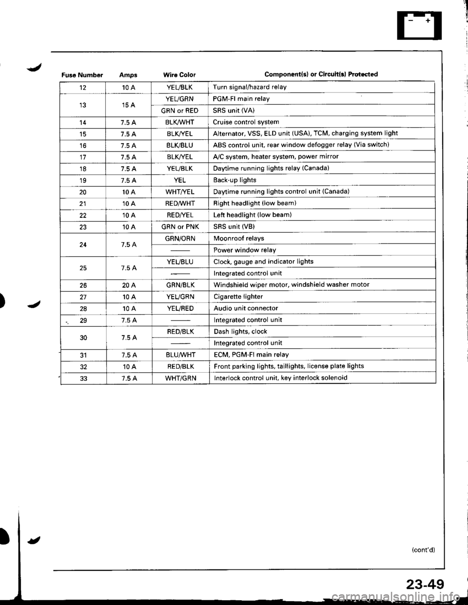
't210AYEUBLKTurn signal/hazard relay
15 AYEUGRNPGM-Fl main relay
GRN or REDSRS unit (VA)
147.5 ABLK/WHTCruise control system
15BLK/YE LAlternator, VSS, ELD unit (USA), TCM, charging system light
't67.5 ABLVBLUABS control unit, rear window defogger relay (Via switch)
117.5 ABLK//ELAVC system, heater system, power marror
187.5 AYEUBLKDaytime running lights relay (Canada)
197.5 AYELEack-up lights
2010 AWHT/YELDaytime running lights control unit (Canada)
2110 ARED/WHTRight headlight (low beam)
2210 ARE D|YE LLett headlight (low beam)
2310 AGRN or PNKSRS unit (VB)
247.5 AGRN/ORNMoonroof relays
Power window relay
7.5 AYEUBLUClock, gauge and indicator lights
Integrated control unit
2620AGRN/BLKWindshield wiper motor, windshield washer motor
10AYEUGRNCigarette lighter
2810AYEUREDAudio unit connector
29Integrated control unit
30RED/BLKDash lights, clock
Integrated control unit
317.5 A8LU/WHTECM. PGM-Fl main relav
10ARE D/BLKFront parking lights, taillights, license plate lights
7.5 AWHT/GRNInterlock control unit, key interlock solenoid
23-49
Page 1110 of 1681

J
)1 -
Fuso NumborAmpsWir€ ColorComponent(s) or Circuh(rl Protastcd
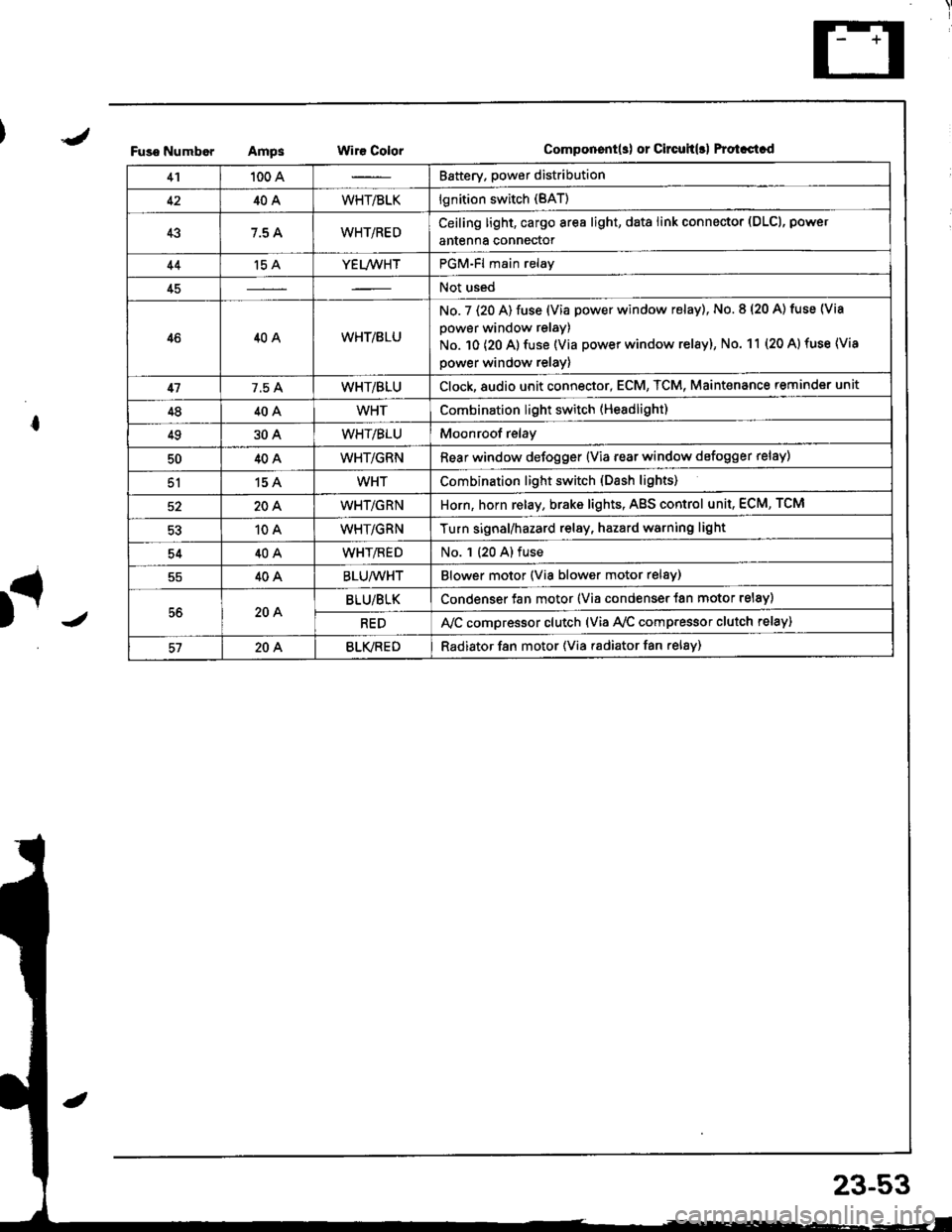
41100 ABattery. power distribution
4240AWHT/BLKlgnition switch (BAT)
437.5 AWHT/REDCeiling light, cargo area light, data link connector (DLCl, power
antenna connector
44't5 AYEL/WHTPGM-Fl main relay
45Not used
4640AWHT/8LU
No. 7 (20 A) fuse (Via power window relay), No. 8 (20 A) tuse (Via
power window relay)
No. 10 (20 A) fuse (Via power window relay), No. 11 (20 A) fuse (Via
power window relay)
417.5 AWHT/BLUClock,8udio unit connector, ECM, TCM, Maint€nance reminder unit
4840AWHTCombination light switch (Headlight)
4930AWHT/BLUMoonroof relay
5040AWHT/GRNRear window defogger {Via rear window defogger relay)
51154WHTCombination light switch (Dash lights)
20AWHT/GRNHorn, horn relay, brake lights, AgS control unit, ECM, TCM
10AWHT/GRNTurn signal/hazard relay, hazard warning light
5440AWHT/flEDNo. 1 (20 A) fuse
40ABLU/WHTBlower motor (Via blower motor relsy)
56204BLU/BLKCondenser fan motor (Via condenser {an motor relay)
REDA,/C compressor clutch (via Ay'c comp.essor clutch relay)
57204BLVREDRadiator f8n motor (Via radiator fan relay)
23-53
Page 1113 of 1681
Power Distribution
Gircuit ldentification (cont'd)
No.42 {40AiFUSE(From page 2154)
BLKBLU
ELKBLU
+- BLK/YEL -ABSconlrolunil
Bear window detoggef relay(Via re window delogger swilch)
Oplional connoctor (lc2)
(Via power mircr swilch)
UNOEF,HOOO FUSSF€LAYBOX (To page 23-55)
I
VTo page23-58
BLKWHT
I
V
/ To page 23-59
(Fuse,telay box sockel)
cRN {or REot -i-
BLK'YEL -
Recirdlalion conlrol nolof,/C lhefmoslalMods conlrol motorHealer conlrol panel
oaylime running lights relay (Canada)
near washor molor(Via rear wiper^vasher swilch)
lgnilion coil
Tuln signal/harad relay(via swrtcl)
PGM.FI main relay
SRS unil (VA)
Cruise conlrol unit
BLK,TYEL --- Alernalorr_. TcM
BLK/YEL ---t- vss- E-D Jril (JSAj
Charging syslem l€hl
UNDEB-DASH FIJSE/RELAY BOX
N0.18 (7.5A)
N0.14 (7.5A)
IGN]TION SWI'TCH
\ Acc
23-56
Page 1117 of 1681
Power Distribution
Circuit ldentification (cont'd)
RED/BLU -
RED/GRN -
REOMHT -
Righl headlighl (High beam)
High beam indicalo. light
Lelt headlighl (High beam)
Righl headlighl (Low beam)
Letl headlighr (Low beam)
Inlegraled conlrol unn
Optional conneclor (Dash lighls)
Inleglaled conlrol unh
(Flsorelay box so*el)
(Flssrelay bot sock€l)
(Fuse/relay box sodet)
COMBINATIONLIGHT SW TCH
lo| | PAsslNGto
BEo/BLK -- Healor conlrol panel hghl- Mgear posrton consote tighl
Cigarcfl 6 lighter/ashtray lightsGauge lighlsAudio unit connsclorR€ar window delogg€r swnch tbhtClockHazard wanlng swilci lighlGlove box lightOash lights bnghhess conlroller
Leit II
I lronlparkifC lighl
FighlJ
h",J'n') '"",.*
l"fn' ) 'nn., '.', 'nnt {r"o"n)
23-60
Letl L.Rgh I rrense Prale lrgnl
Page 1161 of 1681

Gharging System
Troubleshooting
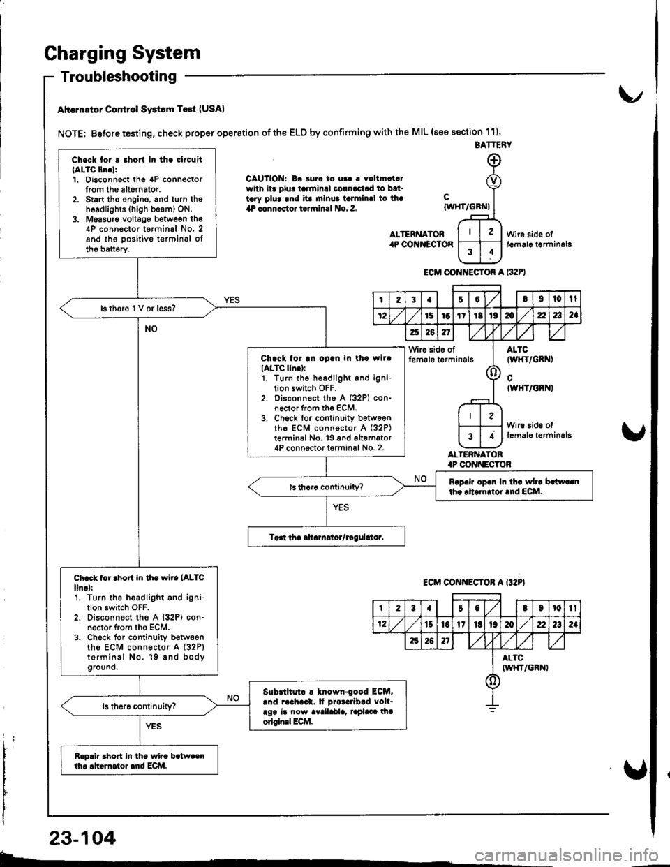
Ahcrn.tor Control Swtom T.rt (USA)
NOTE: Betore testing, check proper operation of the ELD by confirming with the MIL (s€e section 11).
CAUTION: Ba 3urc to ut! | vollmatalwith hr plu! tarmlnal connactad to bat-tary plua and ita mlnua talmlnal to lha4P connactor tarrninal No. 2.
ALTENNATORilP COiINECTOR
cIWHT/GBN}
ALTERNATOR.P CONI{ECTOB
Wire sido olt€m6le t€rminal6
ECM CONI{ECTOR A l:t2F)
BATTERY
Ch.ck tor . .hort In th. clrcuit(ALTC ltn.lr1. Disconnect the 4P connoctorIrom th6 altemator.2. Start tho engine, and turn thoh6adlights (high beam) ON.3. Moasur€ voltago botwoen th64P conn€ctor t6rminal No. 2and the positivo t€rminsl oltho batterv.
16 thor6 1 V or less?
Chrck for .n oD.n In th. wllrIALTC lln.):1. turn the headlight and igni-tion switch OFF.2. Disconnect th6 A (32P) con-noctor from the ECM.3. Ch6ck for continuity b6tw6entho ECM connoctor A (32P)
t€rminal No, 19 and alternator4P connoctor torminal No. 2.
Rrp.h op.n In th. wh. brlw..nth. rltarn oi.nd ECM.
Ch.ct for rhort in th. wire (ALTC
lin.l:'1. Turn the headlight and ignition switch OFF.2. Disconn€ct the A {32P} con-n6ctor from tho ECM.3. Check for conlinuity b€twoenths ECM connector A (32P)
terminal No. 19 8nd bodyground.
Slbrlltut. ! tnown-good ECM..nd rach.ck. It Drorcrlb.d volt-rgr ir now avalldla, raphce lhaorigin.l Ecilt.
Rap.ir 3hort in lha wira bstwaanth. .h.rnator ard ECI\|.
I23{5GtI|l0tl
72151aItIt136zla2a
a26n,/,V
Wir€ side offem6le t€rminals(l
ALTC(wl{T/GRNI
cIWHT/GBNI
Wire 3id€ offemal6 t€rminelg34
ECM CONNECTON A I32P}
t23a50t9t0tt
12t510l1Itt9mz2a2a
62621
ALTCIWHT/GRNI()
23-104
b-.
Page 1179 of 1681
I
rIGauge Assembly
BulbLocations
RIGHT TURN SIGNAL INOICATOR LIGHT ('I.4 WI
BRAKE SYSTEM LIGHT I1.4 WI
DOOR-OPEN INDICATOR LIGHT (1.4 WI
*ABS/SRS INOICATOR LIGHT (1.' W)
LOW FUEL INDICATOR I-IGHT I3.4 W)
SEAT BELT REMINDER LIGHT {1.4 WI
HATCH-OPEN INDICATOR LIGHT {1.4 W}: HarchbackTRUNK'OPEN INDICATOR LIcHT (1.4 W): Sedan
+: On the ABS/SRS printed circuit board
LEFT TURN SIGNAL INDICATOR LIGHT (1.4 WI
CHARGING SYSTEM LIGHT {1,4 WI
A/T GEAR POSITION INDICATOR LIGHT (1.'t2 W x 7)
HIGH BEAM INDICATOR LIGHT I1 .4 \A,
LOW ENGINE OIL PRESSUREINDICATOR LIGHT (1.4 W}
MALFUNCTION INDICATOR LAMP(MtLl (1.4 Wl
LIGHTS13.4 W x 3)REMINDER LIGHT I1.4 WI
cRursE LTGHT | 1.4 Wt
23-122
Page 1192 of 1681

Brake System Indicator
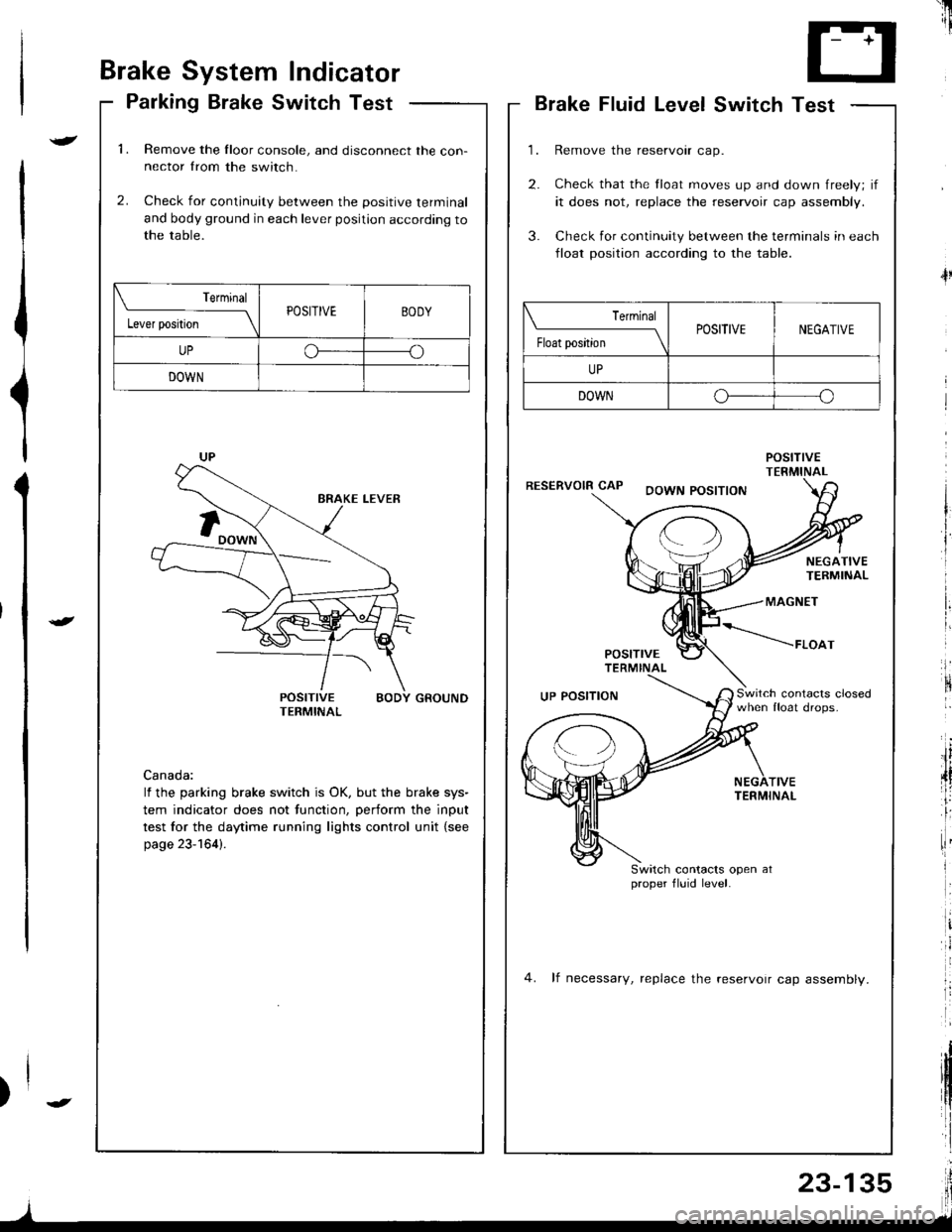
Parking Brake Switch Test
1.Remove the Iloor console, and disconnect the con-nector from the switch.
Check for continuity between the positive terminal
and body ground in each lever position according tothe table.
2.
POSITIVE BODY GROUNDTERMINAL
Canada:
lf the parking brake switch is OK, but the brake sys-
tem indicator does not function, perform the input
test for the daytime running lights control unit {see
page 23-164).
Terminal
l"*rr*ril---ltPOSITIVEBODY
UPoo
DOWN
'il
--r '1i
T- +T
L.J
Brake Fluid LevelSwitch Test
Remove the reservoir cap.
Check that the float moves up and down freely; if
it does not, replace the reservoir cap assembly.
Check for continuity between the terminals in each
lloat position according to the table.
POStnVETERMINALRESERVOIR CAPDOWN POSITION
4l
NEGATIVETERMINAL
MAGNET
POSITTVETERMINAL
*----raoo,
Switch contacrs closedwhen float drops.UP POSITION
TIVETERMINAL
Switch contacts open atproper fluid level.
4. lf necessary, replace the reservoir cap assemblv.
| ermrnal
Float position \POSITIVENEGATIVE
UP
DOWNo--o
I