1998 HONDA INTEGRA alternator
[x] Cancel search: alternatorPage 1172 of 1681
)
t
J
Altelnator ttelr Inspecuon ano Aol
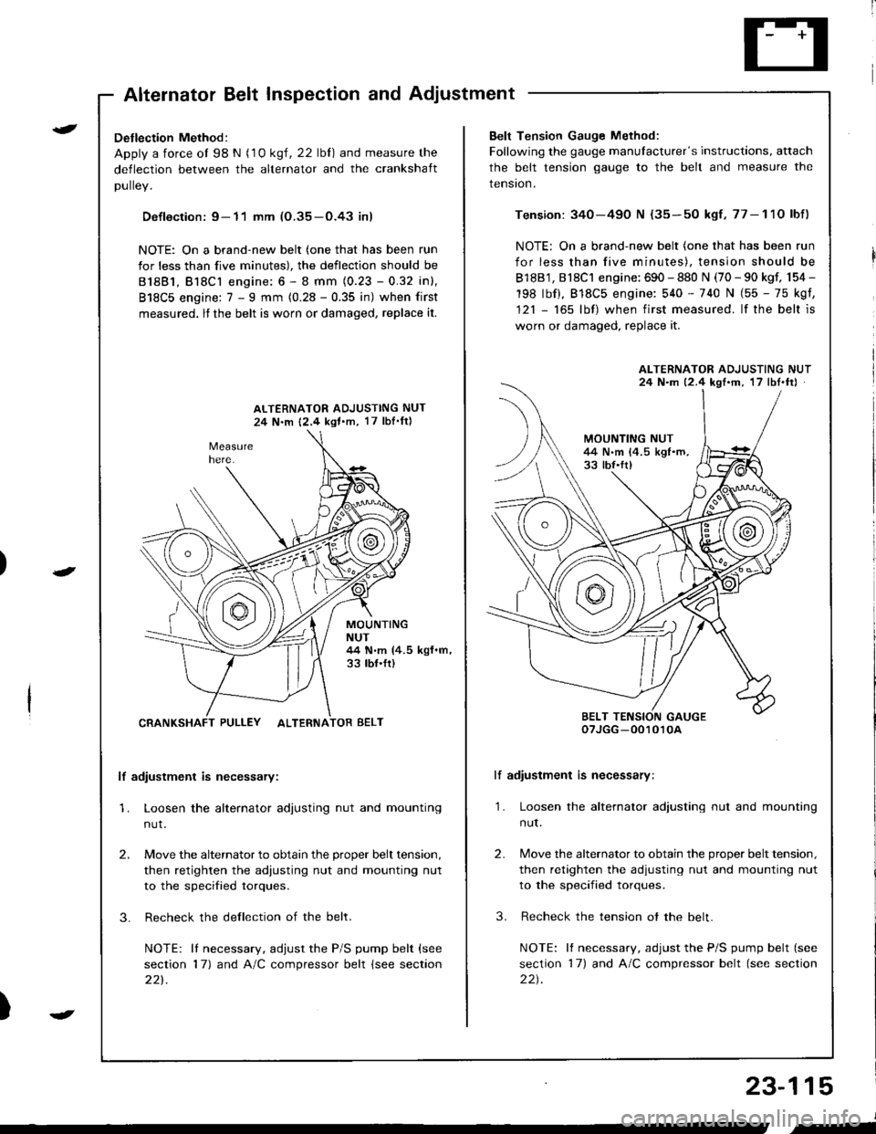
Detlection Method:
Apply a force ol 98 N (1 0 ksl, 22 lbl) and measure the
deflection between the alternator and the crankshaft
DUllev,
Defloction: 9- 11 mm (O.35-O.43 inl
NOTE: On a brand-new belt (one that has been run
for less than five minutes), the deflection should be
81881, Bl8Cl engine: 6 - 8 mm (0.23 - 0.32 inl,
818C5 engine: 7 - I mm (0.28 - 0.35 in) when first
measured, lf the belt is worn or damaged, replace it.
ALTERNATOR ADJUSTING NUT
24 N.m 12,4 kgl.m, 17 lbI'ftl
MOUNTINGNUT44 N.m (4.5 kgf.m,33 tbf.ft)
CRANKSHAFT PULLEY ALTERNATOR BELT
lf adiustment is necessary:
1. Loosen the alternator adjusting nut and mounting
nut.
2.
3.
Move the alternator to obtain the proper belt tension,
then retighten the adiusting nut and mounting nut
to the specified torques.
Recheck the dellection of the belt.
NOTE: lI necessary, adjust the P/S pump belt (see
section 17) and A/C compressor belt (see section
221.
Belt Tension Gauge Method:
Following the gauge manulacturer's instructions, attach
the belt tension gauge to the belt and measure the
tension.
Tension: 340-490 N {35-50 kgf,77-11O lbf)
NOTE: On a brand-new belt (one that has been run
for less than five minutes), tension should be
818B1, 818C1 engine: 690 - 880 N (70 - 90 kgf, 154 -
198 lbf), 818C5 engine: 540 - 740 N (55 - 75 kgf,
121 - 165 lbf) when first measured. lf the belt is
worn or damaged, replace it.
lf adiustment is necessary:
1. Loosen the alternator adjusting nut and mounting
nut.
2.
3.
Move the alternator to obtain the proper belt tension,
then retighten the adjusting nut and mounting nut
to the specified torques.
Recheck the tension ot the belt.
NOTE: It necessary, adjust the P/S pump belt (see
section 17) and A/C compressor belt (see section
22t.
ALTERNATOR ADJUSTING NUT24 N.m 12.4 kgf'm, 17 lbt.ftJ
BELT TENSION GAUGEoTJGG -0010r0A
23-115
J
,-
Page 1182 of 1681
J
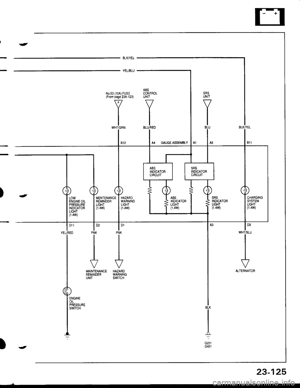
BLKYEL
YEUBLU
A8SN0.53 (104) FUSE CONTROLlFrofi page 23A'123) UNIT
VV
II
tltlWHT/GFN BLU/REO
lonWHT€IU
I
I
I
\?
ALTERNATOR
lo'PNK
J
HAZAROWARNINGswtTcH
MENTENANCEREMINDERLIGHT0.4v,/i
lo'PNK
II
I
J
MAINTENANCEREMINDERUNIT
| 011
YEUREO
I
T
P"-:
)-
BLK
I:
G201G401
LOWENGINE OILPFESSUREINDICATORLIGHT0.4w)
23-125
)J
Page 1386 of 1681
)o
)a
)wer IJrstnDullon Scnemallcs -
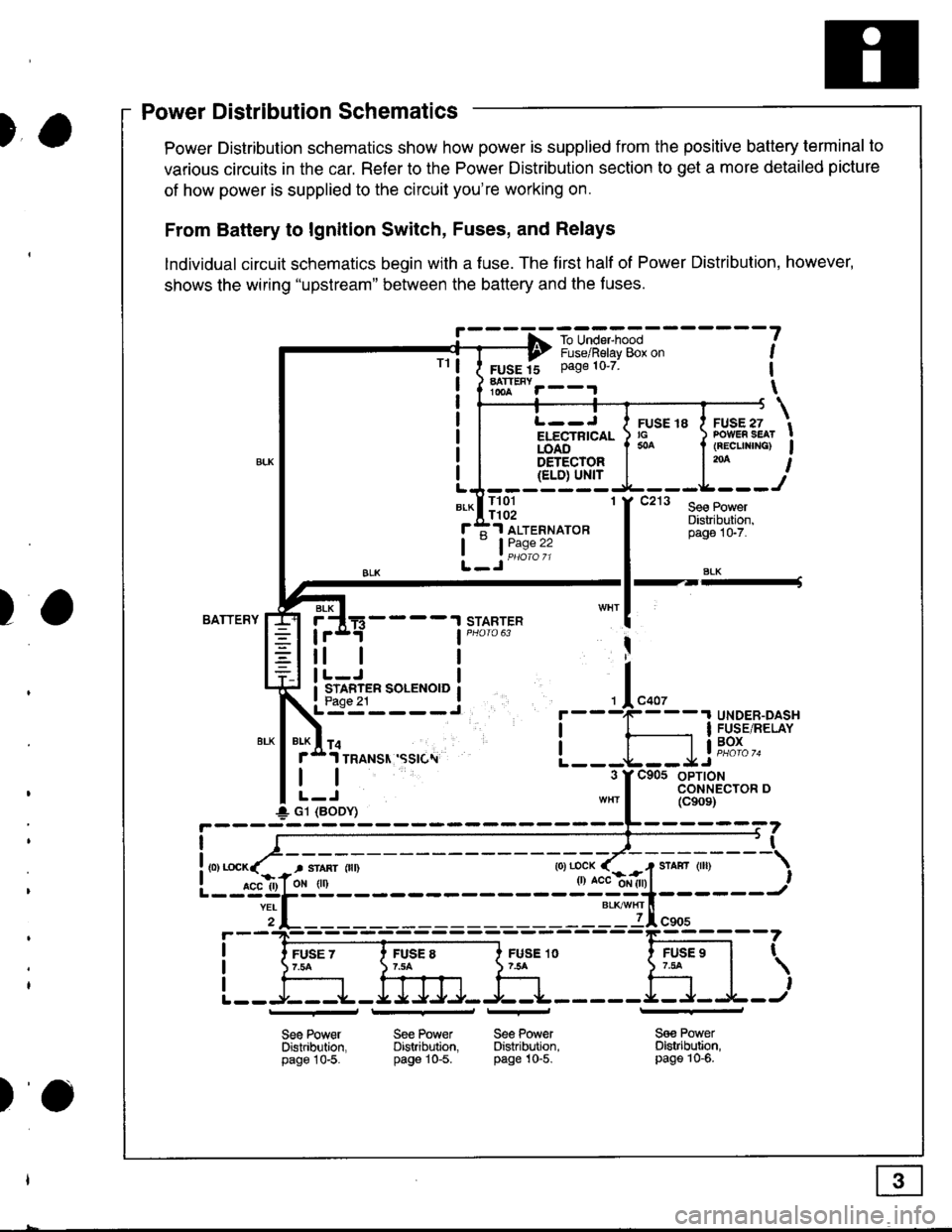
Power Distribution schematics show how power is supplied from the positive battery terminal to
various circuits in the car. Refer to the Power Distribution section to get a more detailed picture
of how power is supplied to the circuit you're working on.
From Battery to lgnition Switch, Fuses, and Relays
lndividual circuit schematics begin with a fuse. The first half of Power Distribution, however,
shows the wiring "upstream" between the battery and the f uses.
!' - - - -f -ro-unE,-"*l - - - - - - -
?---? i,"-")il"i"v-g& o" ,
FUSE 15 Page 10'7 1
hTt""r--.r \
TrL--J I ruse re I ruse zi/ ru:rE ro a .v-E., tELECTRTCAL ) rc ) PowER sEAr !iOA6".'-'- I * I (REcuNrNG) Igs-r-qqrg! | l'* I{ELD) Ul'{rLJ-------
*-lll3l 'f t"' l*.r:::f ;1 ALTERNAToR
tL_Jii1:"":
Distribuiion,pago 1G7.
SLK
BATTERYSTARTERBLK
4----t
tl
STARTER SOLENOID
I
I
+ G1 (BODY)
r
I
I
I
FUSE 1O754
Sge PowerDistribltion,page 10-5.
FUSE 97.tat
,
l---r+J
See Power Se€ PowerDistribution. Distribution.page 10-5. pag€ 10-5.
_l_
Sa€ PowerDistribution,page 10-6.
Power Distribution Schematics
tt
)o
Page 1395 of 1681
How To Use This Manual
Test Equipment
lf, in addition, you need to know exactly how
much resistance there is between two ooints.
use a digital volVohmmeter (DVOM).
In the "oHMS" range, the DVOM will show
resistance between two points along a circuit.
Low resistance means good continuity.
Diodes and solid-state devices in a circuit can
make a DVOM give a false reading. To check
a reading, reverse the leads, and take a
second reading. lf the readings differ, the
component is affecting the measurement.
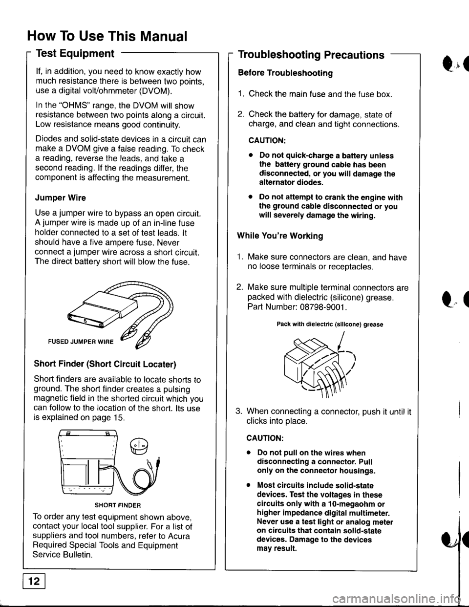
Jumper Wire
Use a jumper wire to bypass an open circuit.
A jumper wire is made up of an in-line f use
holder connected to a set of test leads. lt
should have a tive ampere fuse. Never
connect a jumper wire across a short circuit.
The direct battery short will blow the fuse.
Short Finder (Short Circuit Locater)
Shoft linders are available to locate shorts to
ground. The short finder creates a pulsing
magnetic field in the shorted circuit which you
can follow to the location of the short. lts use
is explained on page 15.
SHORT FINDER
To order any test equipment shown above,
contact your local tool supplier. For a list of
suppliers and tool numbers, refer to Acura
Required Special Tools and Equipment
Service Bulletin.
Troubleshooting Precautions
Before Troubleshooting
1. Check the main fuse and the fuse box.
2. Check the battery for damage. state of
charge, and clean and tight connections.
CAUTION:
. Do not quick-charge a battery unless
the battery ground cable has been
disconnected, or you will damage the
alternator diodes.
. Do not attempt to crank the engine with
the ground cable disconnected or you
will severely damage the wiring.
While You're Working
1. Make sure connectors are clean, and have
no loose terminals or receotacles.
2. Make sure multiple terminal connectors are
packed with dielectric (silicone) grease.
Part Number: 08798-9001 .
Pack with dielectric (silicone) grease
When connecting a connector, push it until it
clicks into olace.
Do not pull on the wires when
disconnecting a connector. Pull
only on the connector housings.
Most circuits include solid-state
devices. Test the voltages in these
circuits only with a 1o-megaohm or
higher impedance digital multimeter.
Never use a test light or analog meter
on circuits that contain solid-state
devices. Damage to the devices
may result.
Qr(
l"(
Page 1401 of 1681
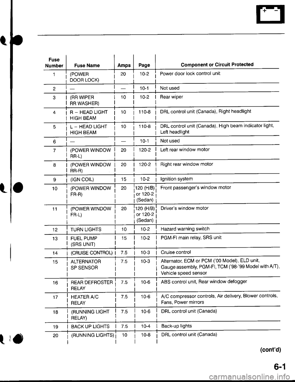
Fuse
NumberFuse NameAmpsPagecomponent or circuit Protected
(POWER
DOOR LOCK)
(RR WIPER
RR WASHER)
R _ HEAD LIGHT
HIGH BEAM
j 1o-2Power door lock control unit
10-2 | Rear wiper
I
tto-e i onLcontrol unit (Canada), Right headlight
L _ HEAD LIGHT
HIGH BEAM
(POWER WINDOW
RR-L)
i 1 10-8i DRL control unit (Canada), High beam indicator light,
i Left headlight
1 0-1Not used
| 1zo-z
I
I Left rear window motor
| (lGN colL)| 15
(POWER WINDOW
FR-R)
(POWEB WINDOW
FR-L)
I Right rear window molor
I
Front passenger's window motol
Driver's window motor
| 120-2
i120 (H/B)
iot 120-2
l(Sedan)
i120 (H/B)
l0:120 ?
IJ13
TURN LIGHTS
FUEL PUMP
(SRS UNIT)
(Sedan)
'lo-2Hazard warning switch
1O-2 | PGM-FI main relay, SRS unit
I
14I (cRUlsE coNTRoL) | 7.510-3 | Cruise control
ALTERNATOR
SP SENSOR
7.510-3Alternator, ECM or PCM ('00 Model), ELD unit,
Gauge assembly, PGM-Fl, TCM ('98-'99 Modelwith A/f),
Vehicle speed sensor
i REAR DEFBOSTER ii RELAY i
10-6i ABS control unit, Rear window defogger
I HEATER A/C
: RELAY
fuC compressor controls, Air delivery, Blower controls,
Fans. Power mirrors
I tnururutruc ucxr I z.s
I otrt av I
I DRL control unit (Canada)10-6
I BACK UP LIGHTS | 7.s | 10-4 I Back-up lights
t
(RUNNTNG LTGHTS) ii DRL control unit (Canada)
(cont'd)
19
6-1
Page 1411 of 1681
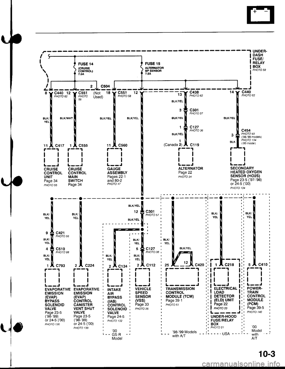
I
I
\
i
FUSE 14(cFUlsEcorrEoLl
FUSE 15alTEaxAron8P SEt{904?.54
UNDER.DASHFUSE/RELAYBOX
\
I
I
8
BLl(YEI
c504
C551 (Not 18
floro used)c551 12PHOfO 58
c560
GAUGEASSEMBLYPages 22-1and 80-2
c440
:l
c410
c440 '12
PHO|O 625A
BLK/WH'
c417 I l' C555
tl
llL--J L--JCRUISE CRUISECONTROL CONTROLUNIT MAINPage 34 SWITCHPHaro s5 Page 34
i#r'
14
tl
BLK I 8lK lt Y pHoto5l ,YEL I YEL I -..-",-. I
:;;:t:i;r
r[-;:i-j:t ;i
".-.,..f,
t'to"
i I ii i'L'lt
BLK/^YEL
12 g c301
c127
tl
ALTERNATORPage 22
,I
SECONDARYHEATED OXYGENSENSOR (H02S)Page 23 5 ('97-�98)or 24-5 ('00)
I er-xi, YEL
9 4 C421
4 g c510
":'.!.^--^ I : I :"1'I^-^- i""! ",",. ;i
"".%',3,. ! : I :'f,,"#5."1 !;I; ;i
i.,II i :l',JI .1',IT :i'Ll ! :1,T.1 r"'Ll i V | :i
c7s3 ,l"rro i ,4"'.0 ' ,,1[s112 izsrz [ ^---:lf :f^--:]r A czgs zlczzq i zAcrgq ' 2Ac1't2 ' 25 X- -':-A c420:' | 1Ac2r8
[l i--l ii--l ii--l ii-----l ii!i'--l| | r | :t | ' I I :t ! ':l!
| | | | rl l:l | :l l:;alL--i L--.r I L--j , !--r : L-----r ,i i r-=l ,EVAPORATIVE EVAPORATIVE ' IHTAXC : VEHICLE : TRANSMISSION :; ; EIEqTRICAL
EMISSION EMISSION , AtR ; SPEED ' CONTROL :' ! !o49 -: BypASS , SENSOR ' MODULE fiCM):'! !%9
ie.vfD- F!Afl,-. ; iiiirss : 9F,lIioR ' l|oDtllEficM) ;:l LTl9.r.?f
I
bvpads aoNThoL i rAat- ' (vss) ' Pase 3s 1 ': i (ELD)-uNlr
soLENolD caNlsTER ; bor.!n.o1 ' Page 33 ', euo,o,, :: I l.?^s_"^l?VALVE VENTSHUT , SOLENOTD , pHora 26 , :,4 Ptloro 23 |Paoe 23-5 VALVE ' VALVE ;' L--- - J(96-99) Page23-5 i paqe 24-5 | : 'IUNDER-HOODor24-5(00) f98- 99) , pdato t32 : : ':FUSE/RELAYorz+-3(uul (Yo-w/ | pHaro 132 :, FusPHoro 136 or 24 5 ('00) : , BOXu,.eJ\vv/PHOfO 139 | ,t PHOTO21
l--33. -j :-- ee-�ss lvodels --:l---.usA ---
Model
:lrt I
; POWER-, TRAIN' CONTROL' MODULE
: (PCM), Page 39-5
, '00
, Model'- with -.,lo
10-3
Page 1433 of 1681
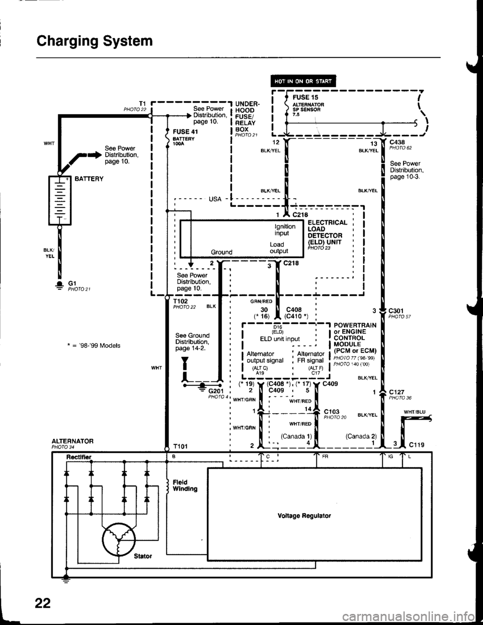
Charging System
1;+ Sl"Jlit*"'
BATTERY
lGl
Ses Power
* = 98- 99 f,rodels
ALTERNATOR
lgnitioninput
Load
Ground oulpur
22
Page 1598 of 1681
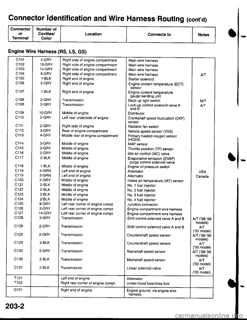
Connector ldentification and Wire Harness Routing (cont,d)
Connector
or
Terminal
Number ot
Cavities/
Color
LocationConnects toNotes
Engine Wire Harness (RS, LS, GS)
c101
c102
c103
c104
c105
c106
c 107
c108
c108
c'1 09
c110
c111
cl12
c113
c'114
c115
c116
c117
c118
c119
c1 19
c120
c121
c122
c123
c124
cl25
cl26
c127
Ql28
c128
c129
c 129
c130
c'l30
c131
4.GRY
1O.GRY
14-GRY
6-GRY
1.BLK
2-GRY
,1-BLK
2-GRY
2.GRY
1O-GRY
2-GRY
2-GRY
3-GRY
4-GRY
3-GRY
3-GRY
2-GRY
2.BLK
.1-BLK
4-GRN
3-GRN
2-GRY
2.BLK
2-BLK
2-BLK
2.BLK
8-GRY
2-GRY
14-GRY
3-GRY
2.GRY
2.GRY
2-BLK
3-GRY
2-BLK
2-BLK
Right side of engine compartment
Right side of engine compartment
Right side ot engine compartment
Right side of engine compartment
Right end of engine
Right end of engine
Right end of engine
Transmission
Transmission
lvliddle ol engine
Lett rear underside of engine
Right side ol engine
Rear of engine compartment
Middle rear ol engine compartment
Middle ol engine
Middle of engine
Middle ol engine
l\4iddle of engine
Middle of engine
Left end ot engine
Lett end of engine
Middle of engine
N,liddle ol engine
Middle of engine
Middle of engine
Middle of engine
Left rear corner of engine compt.
Lelt rear corner of engine compt.
Left rear corner of engine compt.
Transmission
Transmission
Transmission
Transmission
Transmission
Transmission
Transmission
Main wire harness
Main wire harness
Main wire harness
Main wire harness
Starter solenoid
Engine coolant temperature (ECT)sensor
Engine coolant temperaturegauge sending unit
Back-up light switch
Lock-up control solenoid valve Aand B
Distributor
Crankshaft speed fluctuation (CKF)sensor
Radiator fan switch
Vehicle speed sensor (VSS)
Primary heated oxvoen sensor(H02s)
MAP sensor
Throttle position (TP) sensor
ldle air control (lAC) valve
Evaporative emission (EVAP)purge control solenoid valve
Engine oil pressure switch
Alternator
Alternator
Intake air temperature (lAT) sensor
No. I fuel injector
No. 2 fuel injector
No. 3 tuel injector
No. 4 fuel injector
Junction connector
Engine compartment wire harness
Engine compartment wire harness
Shitt control solenoid valve A and B
Shift control solenoid valve A and B
Countershaft speed sensor
Countershatt speed sensor
lvtainshatt speed sensor
Mainshaft speed sensor
Linear solenoid valve
NT
[/VT
A"/T
USA
Canada
A/T (98199models)
AIT('00 model)
A,/T ('98-'�99models)
('00 model)
A,/T f98-'99models)
Atf('00 model)
AN('00 model)
T101
T102
Left end of engine
Right rear corner of engine compt.
Alternator
Under-hood fuse/relay box
G'101Right end ot engineEngine ground, via engine wirenarness
o
I
203-2