Page 1163 of 1681
From previol.rs page
The charging swtem is OK.lsthe amperage 70 A or more?
Alternator/Regulator Test-4:With the engine speed still at2,000 rpm, Iull-Iield the alternator.
Charging System
Troubleshooting (cont'dl
CAUTION: Th6 voltago will rise quickly when the ahernator is ful!fieldcd. Do not .llowth6 voltag€ to €xc6ed 18 V; it may damage tho ol6drical system.
NOTE: Attach a probe to the VAT'40 full field test lead, and insert the probe into the lullfield access hole at the back of the alternator. Switch the field selector to the "A {Ground}"position momentarily, and check the amperage reading.
REGULATOB(Located inside
FULL FIELOACCESS HOLE
END COVEB
END COVER
FULL FIELDACCESS HOLE
L^
23-106
Page 1164 of 1681
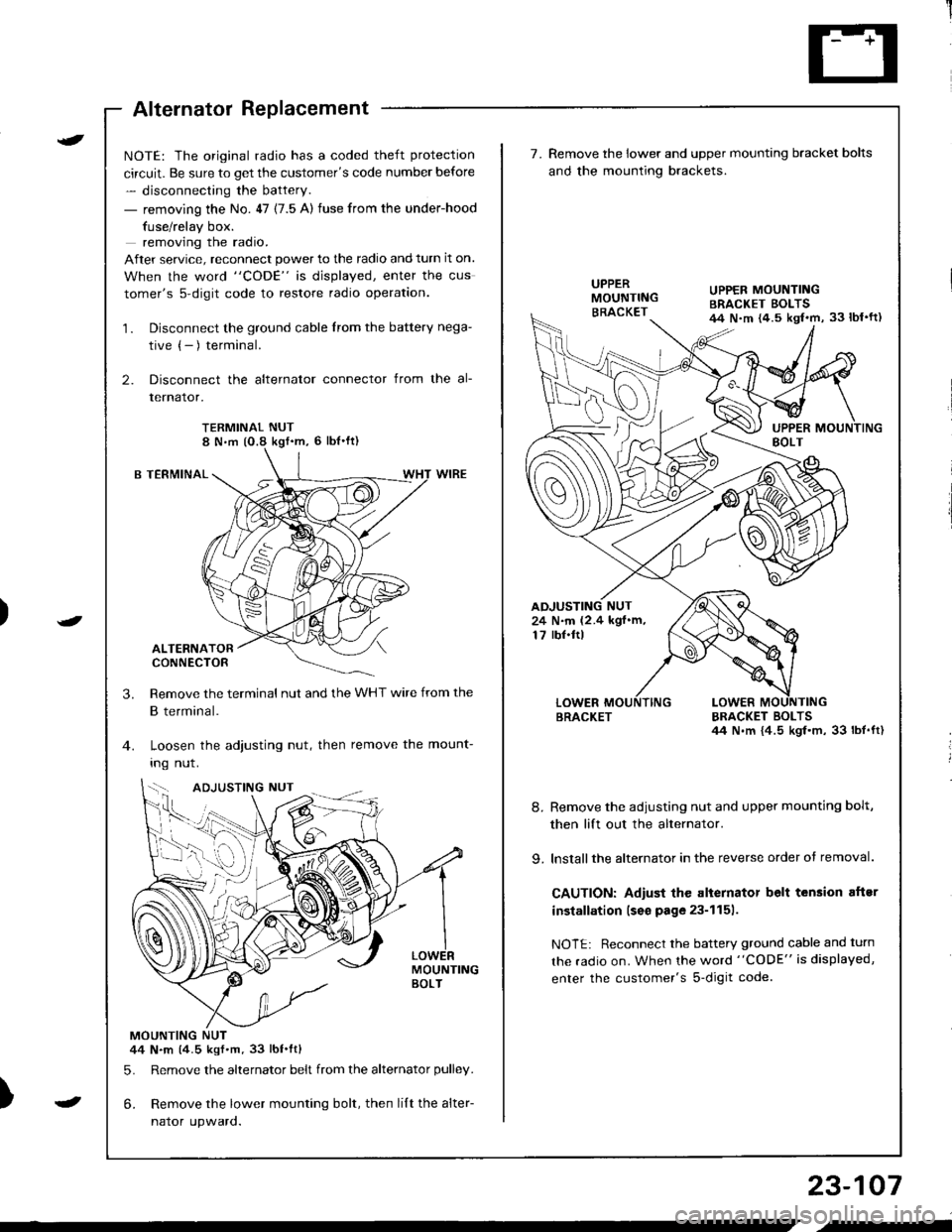
Alternator Replacement
)
t
-
NOTE: The original radio has a coded theft protection
circuit. Be sure to get the customer's code number before
- disconnecting the battery.
- removing the No. 47 (7.5 A) fuse from the under-hood
fuse/relay box.
removing the radio.
After service, reconnect power to the radio and turn it on.
When the word "CODE" is displayed, enter the cus
tomer's s-digit code to restore radio operation.
1. Disconnect the ground cable from the battery nega-
tive (- ) terminal.
2. Disconnect the alternator connector from the al-
lernalor,
TERMINAL NUT8 N,m (O.8 kgf'm, 6 lbl'ft)
B TERMINAL
ALTERNATORCONNECTOR
Remove the terminal nut and the WHT wire from the
B terminal.
Loosen the adjusting nut, then remove the mount-
Ing nut.
MOUNTINGBOLT
MOUNTING NUT44 N.m (4.5 kgf.m.33 lbt.ftl
5. Remove the alternator belt from the alternator pulley.
6. Remove the lower mounting bolt, then lilt the alter-
naror upwaro.
3.
{--,
7.Remove the lower and upper mounting bracket bolts
and the mounting brackets.
BRACKET BOLTSil4 N.m {4.5 kgl.m, 33 lbt.ft)
8. Remove the adiusting nut and upper mounting bolt,
then lift out the alternator.
9. lnstallthe alternator in the reverse order of removal.
CAUTION: Adiust the alternator belt tension aftsr
installation lseo page 23-1151.
NOTE: Reconnect the battery ground cable and turn
the radio on. When the word "CODE" is displayed,
enter the customer's s-digit code.
BRACKET
UPPER MOUNTINGBRACKET EOLTS44 N.m {4.5 kgl.m, 33 lbl'ft)
24 N.m (2.4 kgf.m,17 rbf.ftl
b-h..K
) I
23-107
-
,-
Page 1165 of 1681
Charging System
Alternator Overhaul
CAUTION: Do not remove the pulley unless the tront
bearing needs replacement.
To loosen the pulley locknut, use 10 mm and 22 mm
wrenches. lf necessary, use an impact wrench.
DENSO:
PULLEY LOCKNUT1'11 N.ft (11.3 kgf.m,82 lbt.ft)
FRONT BEARING
STATOR/DRIVE ENDHOUSINGOENSO:Test, page 23-1'10MITSUBISHIITest, page 23-112
PULLEY
CAUTION: Do not get grease
or oil on the slip rings.
BRUSH HOLDERINSULATOR
offiEND COVER
k-"o*"... ".,"' BRACKET
23-108
L_�
ROTOR
PULLEY
10 mm 8OX WRENCH
BEARING
Page 1166 of 1681
RectifierTest
DENSO:
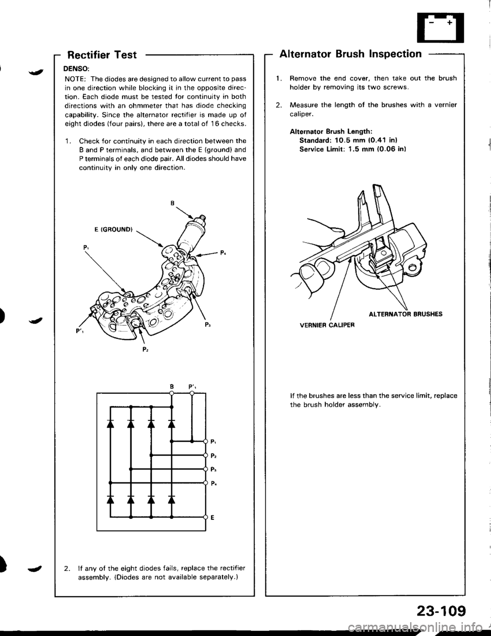
NOTE: The diodes are designed to allow current to pass
in one direction while blocking it in the opposite direc-
tion. Each diode must be tested tor continuity in both
directions with an ohmmeter that has diode checking
capability. Since the alternator rectifier is made up ot
eight diodes (four pairs), there are a total of 16 checks.
'1. Check for continuity in each direction between the
B and P terminals, and between the E (ground) and
P terminals of each diode pair. All diodes should have
continuity in only one direction.
lf any of the eight diodes fails, replace the recti{ier
assembly. iDiodes are not available separately.)
2.
AlternatorBrushInspection
l.Remove the end cover, then take out the brush
holder by removing its two screws.
Measure the length of the brushes with a vernier
caliper.
Altelnator Brush Length:
Standard: 1O.5 mm {O.41 in}
Service Limit: 1.5 mm (0.06 in)
2.
lf the brushes are less than the service limit, replace
the brush holder assembly.
VERNIER CALIPER)
{
J
)
23-109
J
.-
Page 1167 of 1681
Charging System
Rotor Slip Ring Test
DENSO:'l . Check that there is continuity between the slip rings.
ROTOR SHAFT
Check that there is no continuity between the slip
rings and the rotor or rotor shaft.
lf the rotor fails either continuity check, replace the
alternator.
Stator Test
1 . Check that there is continuity between each pair ot
leads.
Check that there is no continuity between each lead
and the coil core.
lf the coil lails either continuity check, replace the
alternator.
2.
3.
2.
3.
23-110
cotl coRE
b-.
Page 1169 of 1681
Gharging System
Reetifier Removal (cont'd)
MITSUBISHI:
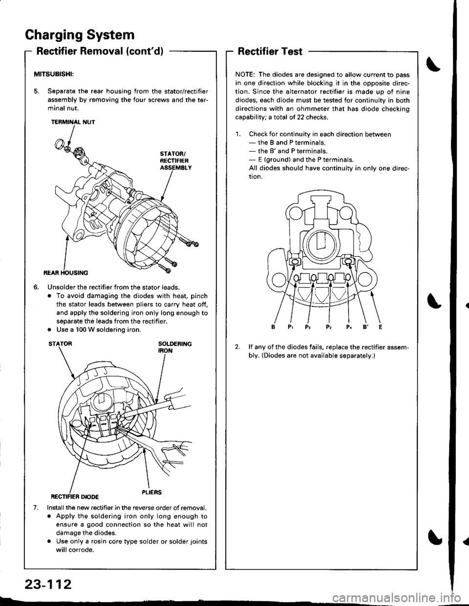
5. Separate the rear housing from the stator/rectifier
assembly by removing the four screws and the ter-
minal nut.
6.
1.
Unsolder the rectifier from the stator leads.
. To avoid damaging the diodes with heat, pinch
the stator leads between pliers to carry heat off,
and apply the soldering iron only long enough to
separate the leads from the rectifier.
. Use a 100 W soldering iron.
Installthe new rectifier in the reverse order of removal.
. Apply the soldering iron only long enough to
ensure a good connection so the heat will not
damage the diodes.
. Use only a rgsin core type solder or solder joints
will cor.ode.
RectifierTest
NOTE: The diodes are designed to allow current to pass
in one direction while blocking it in the opposite direc-
tion. Since the alternator rectifier is made up of nine
diodes, each diode must be tested for continuity in both
directions with an ohmmeter that has diode checkino
capability; a total of 22 checks.
1. Check for continuity in each direction between- the B and P terminals.- the B' and P terminals,- E (ground) and the P terminals.
All diodes should have continuity in only one direc-
uon.
2.lf any of the diodes fails, replace the rectifier assem-
bly. (Diodes are not available separately.)
b.�
23-112
{
Page 1170 of 1681
i'[
Rotor Slip Ring TestAlternator Brush Inspection
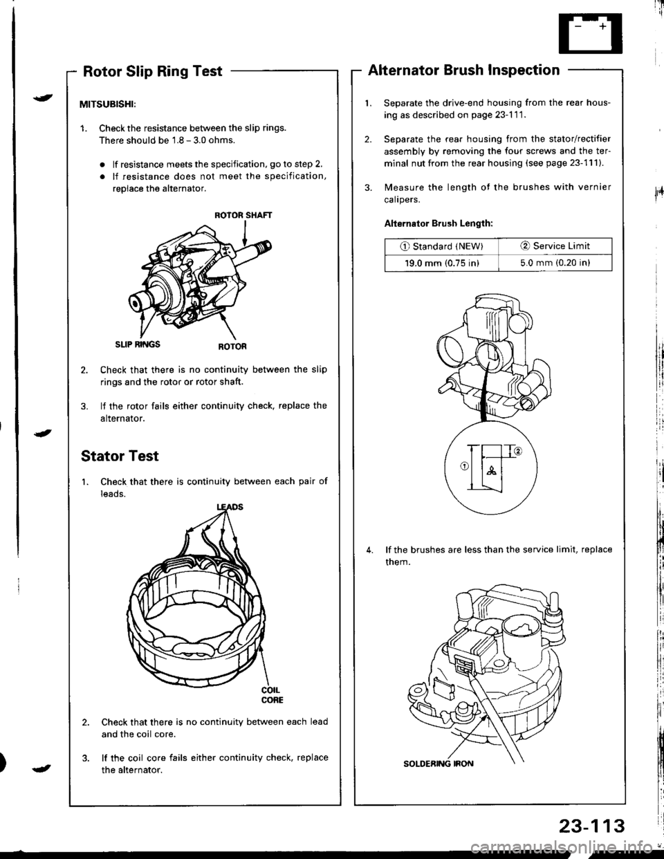
Separate the drive-end housing from the rear hous-
ing as described on page 23-l 1 1.
Separate the rear housing from the stator/rectifier
assembly by removing the four screws and the ter-
minal nut from the rear housing (see page 23-111).
Measure the length of the brushes with vernier
calrpers.
Alternator Brush Length:
O Standard (NEW)O Service Limit
19.0 mm (0.75 in)5.0 mm (0.20 in)
lf the brushes are less than the service limit, replace
them.
23-113
{
J
lFr
MITSUBISHI:
1. Checkthe resistance between the slip rings.
There should be 1.8 - 3.0 ohms.
. lf resistance meets the specification, go to step 2,
. lf resistance does not meet the specification,
replace the alternator.
SLIP RII{GS
Check that there is no continuity between the slip
rings and the rotor or rotor shaft.
lf the rotor fails either continuity check, replace the
alternator.
Stator Test
1. Check that there is continuity between each pair of
leads.
co|LconE
Check that there is no continuity between each
and the coil core.
lf the coil core fails either continuity check, replace
the alternator.
ROIOR SHAFT
J
"-
Page 1171 of 1681
Gharging System
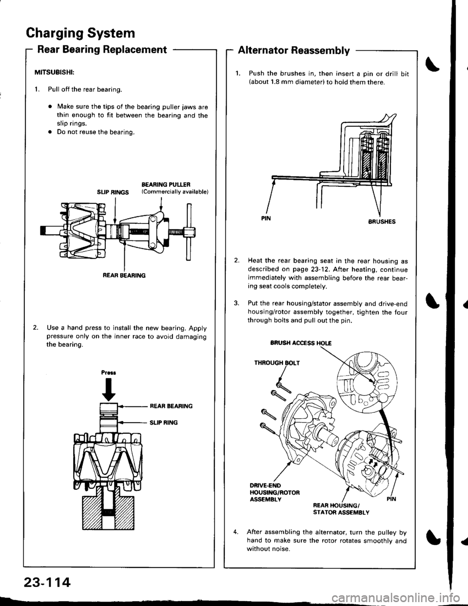
Rear Bearing ReplacementAlternator Reassembly
MITSUBISHI:
1. Pull off the rear bearing.
Make sure the tips of the bearing puller jaws are
thin enough to fit between the bearing and the
slip rings.
Do not reuse the bearing.
BEARING PULITRSLIPRINGS (Commorciallyav6ilable)
Use a hand press to install the new bearing. Applypressure only on the inner race to avoid damaging
the bearing.
23-114
L : -
REAR BEARING
1.Push the brushes in, then insert a pin or drill bit(about 1.8 mm diameter)to hold them there.
ARUSHES
Heat the rear bearing seat in the rear housing as
described on page 23-12. After heating, continue
immediately with assembling before the rear bear-ing seat cools completely.
Put the rear housing/stator assembly and drive-end
housing/rotor assembly together, tighten the four
through bolts and pull out the pin.
THROUGH BOLT
*,
DRIVE.ENDHOUSI'{G/ROTORASSEMBLYREARSTATOR ASSEMSLY
After assembling the alternator. turn the pulley byhand to make sure the rotor rotates smoothlv and
without noise.
BRUSH AOCCSS HOI,"€