Page 156 of 1681

Grankshaft
Removal (cont'dl
Use the wooden handle ot a hammer to drive the
pistons out.
CAUTION:
. Take care not to damage the contact surface ot
the metal gasket.
. When removing the piston/connecting rod, take
care not to hit the oil iet (818C1, 818C5 enginesl.
. ll the oil iet nozzle is damaged or bent, replace
the oil iet assembly {818C1, B18C5 engincs.
page 8-9).
Reinstall the rod bearings and caps after removing
each piston/connecting rod assembly.
l\4ark each piston/connecting rod assembly with its
cylinder number to avoid mixup on reassembly.
NOTE; The existing number on the connecting rod
does not indicate its position in the engine, it indi-
cates the rod bore size.
End Play
NOTE: End play should be inspected before removing
crankshaft.
Push the crank firmly away from the dial indicator, and
zero the dial against the end of the crank. Then pull the
crank firmly back toward the indicator; dial reading
should not exceed service limit.
Crankshaft End Play:
Standard (New): 0.10 - 0.35 mm
{0.00'l - 0.014 inl
Service Limit: 0.45 mm 10.018 inl
. lf end play is excessive, inspect the thrust washers
and thrust surface on the crankshaft. Replace parts as
necessary.
NOTE:
. Thrust washer thickness is tixed and must not be
changed either by grinding or shimming.
. Thrust washers are installed with grooved sides fac-
ing outward.
12.
14.
Frlfll
ftl
t
iffi[l
t,,tlr
lt
i
Page 158 of 1681

Cylinder Block
Inspection
1. Measure wear and taper in direction
three levels in each cylinder as shown.
XandYat
{0.24 in}6mm
tFirst
Second
ThirdMeasurement
6 mm 10.24 in)
CYLINDER BORE GAUGE
Cylinder Bore Size:
Standard (N€w): 81.00 - 81.02 mm
(3.189 - 3.190 inl
Service Limit: 81.07 (3.192 inl
Oversize:
0.251 81.25 - 41.27 mm 13.199-3.200 inl
Bore Taoer:
S€rvice Limit: lDifference betwcen first and third
measu;ement) 0.05 mm (0.002 inl
. lf measurements in any cylinder are beyond
Oversize Bore Service Limit, replace the block.
. lf the block is to be rebored, reler to Piston
Clearance Inspection (see page 7-16) after rebor-
I ng.
NOTE: Scored or scratched cylinder bores must be
noneo,
Reboring Limit: 0.25 mm (0.01 inl
ll
:i
I
I
Check the top oI the block for warpage.
Measure along the edges and across the center as
sh own.
SURFACES TO 8E MEASURED
Engine Block Warpage:
B188l engine:
Standard {New}: 0.07 mm (0,003 inl max.
Service Limit: 0.10 mm {0.004 in)
818C1, 818C5 engines:
Standard (Newl:0.05 mm 10.002 inl max.
Service Limit: 0.08 mm (0.003 in)
I
I
rl
LC
'/rz
PRECISION STRAIGHT EDGE
Page 159 of 1681

11
Bore Honing
l/easure cylinder bores as shown on page 7-14.lf the block is to be reused, hone the cylinders andremeasure the bores.
Hone cylinder bores with honing oil and a fine (400
grat) stone in a 60 degree cross-hatch pattern.
NOTE:
. Use only a rigid hone with 400 grit or finer stonesuch as Sunnen, Ammco, or equivalent.a Do not use stones that are worn or oroKen.
When honing is complete, thoroughly clean thecylinder block of all melal particles. Wash the cylin-der bores with hot soapy water, then dry and oilimmediately to prevent rusting.
NOTE: Never use solvent, it wili only redistribute
the grit on the cylinder walls.
lf scoring or scratches are still present in cylinderbores after honing to the service limit, rebore theengine block.
NOTE: Some light vertical scoring and scratching isacceptable if it is not deep enough to catch your fin-gernail and does not run the full length ofthe bore.
NOTE:
. After honing, clean the cylinder thoroughly withsoapy water.o Only scored or scratched cylinder bores must behoned.
4.
7-15
Page 161 of 1681
t
Installation
Bl881, 818C1 enginos:
lf the crankshaft is already installed
'1. Set the crankshaft to BDC for each cylinder.
2, Remove the connecting rod caps, and slip short sec-
tions of rubber hose over the threaded ends of the
connecting rod bolts.
3. Install the ring compressor, and check that the bear-
ing is securely in place.
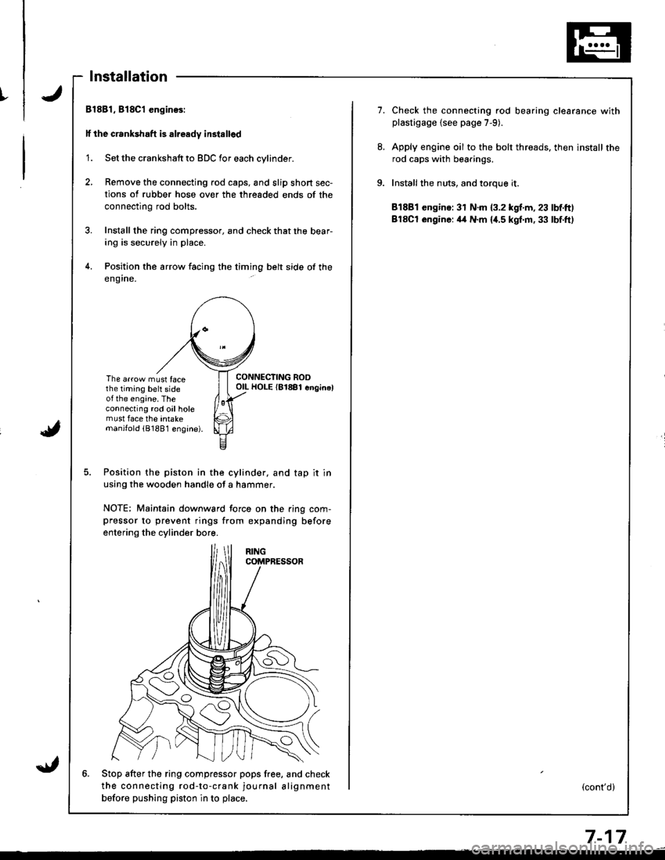
4. Position the arrow facing the timing belt side of the
eng ine.
The arrow must facethe timing belt sideot the engine. Theconnecting rod oil holemust face the intakemanjfold (81881 engine).
CONNECTING ROOOIL HOLE {81881 enginel
Position the piston in the cylinder. and tap it in
using the wooden handle of a hammer.
NOTE; Maintain downward force on the ring com-pressor to prevent rings from expanding before
entering the cylinder bore.
6. Stop after the ring compfessor pops free, and check
the connecting rod-to-crank journal alignment
betore pushing piston in to place,
7.Check the connecting rod bearing clearance withplastigage {see page 7-9).
Apply engine oil to the bolt threads. then install the
rod caps with bearings,
Installthe nuts, and toroue it.
81881 engine: 31 N.m {3.2 kgf.m, 23 lbf.ft)
BlSCt engine: il4 N.m {i[.5 kgf.m, 33 lbf.ft)
(cont'd)
7-17
Page 162 of 1681
I
i
Pistons
Installation (cont'dl
ll the crankshaft is not installed
1. Remove the connecting rod caps, then install the
ring compressor. and check that the bearing is
securely in place.
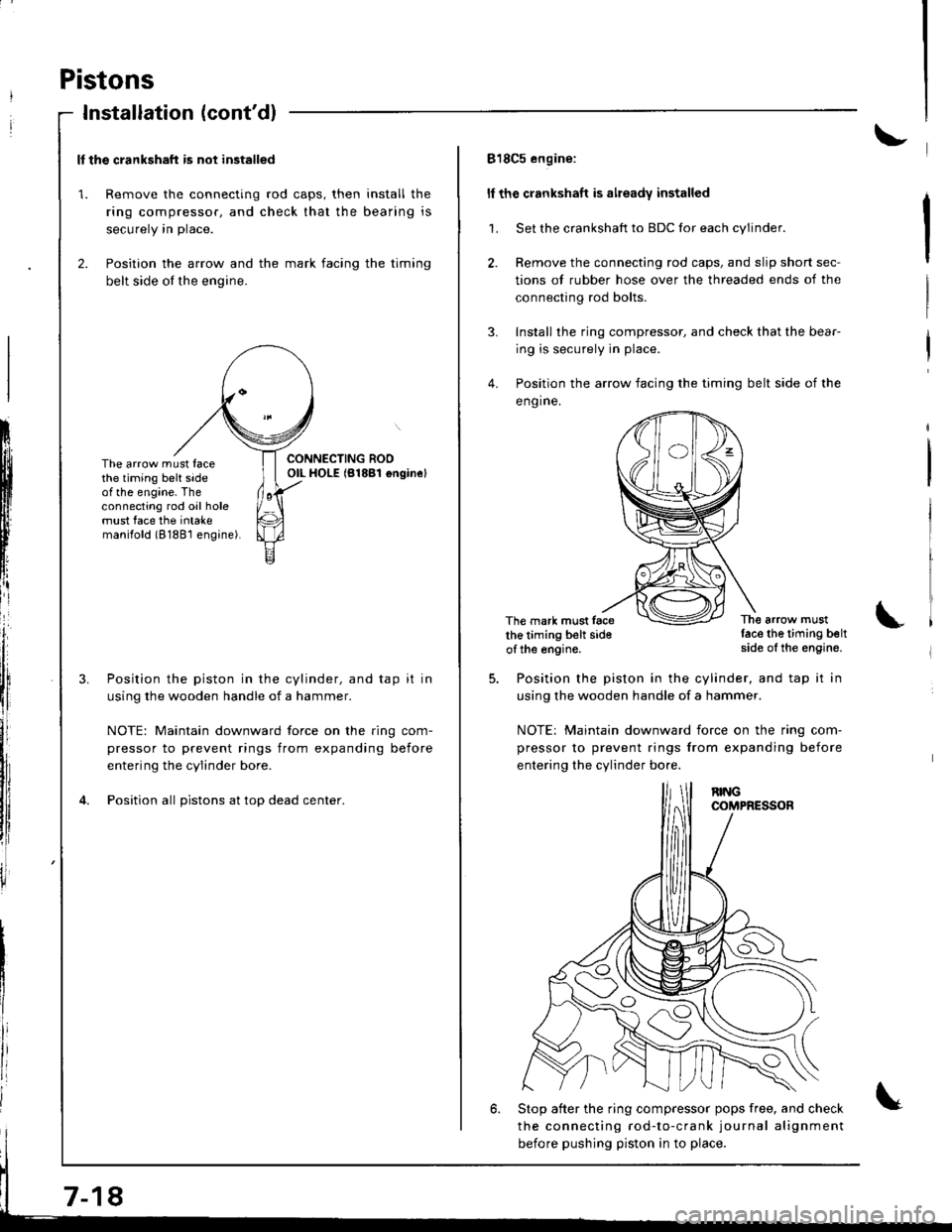
2. Position the arrow and the mark facing the timing
belt side of the engine.
ItIl
Iti
tfll|lflI[lrB
[:
i"lrt
i'
ff
ll,
illi
llillr
il
The arrow must facethe timing belt sideof the engine. Theconnecting rod oil holemust face the intakemanilold (8188'l engine).
Position the piston in the cylinder, and tap it in
using the wooden handle of a hammer.
NOTE: Maintain downward force on the ring com-
pressor to prevent rings from expanding before
entering the cylinder bore.
Position all pistons at top dead center.
7-18
818C5 engine:
ll the crankshaft is already installed
1. Set the crankshaft to BDC for each cylinder.
2. Remove the connecting rod caps, and slip short sec-
tions of rubber hose over the threaded ends of the
connecting rod bolts.
3. Install the ring compressor, and check that the bear-
ing is securely in place.
4. Position the arrow facing the timing belt side of the
eng ine.
The mark must facethe timing belt sideof the engine.
The arrow mustlace the timing beltside of the engine.
Position the piston in the cylinder, and tap it in
using the wooden handle of a hammer.
NOTE: Maintain downward iorce on the ring com-
pressor to prevent rings from expanding before
entering the cylinder bo.e.
6. Stop after the ring compressor pops free, and check
the connecting rod-to-crank journal alignment
before pushing piston in to place.
Page 163 of 1681
I
7.
8.
9.
Check the sonnecting rod bearing clearance withplastigage (see page 7-9).
Apply engine oil to the bolt threads, then install the
rod caps with bearings.
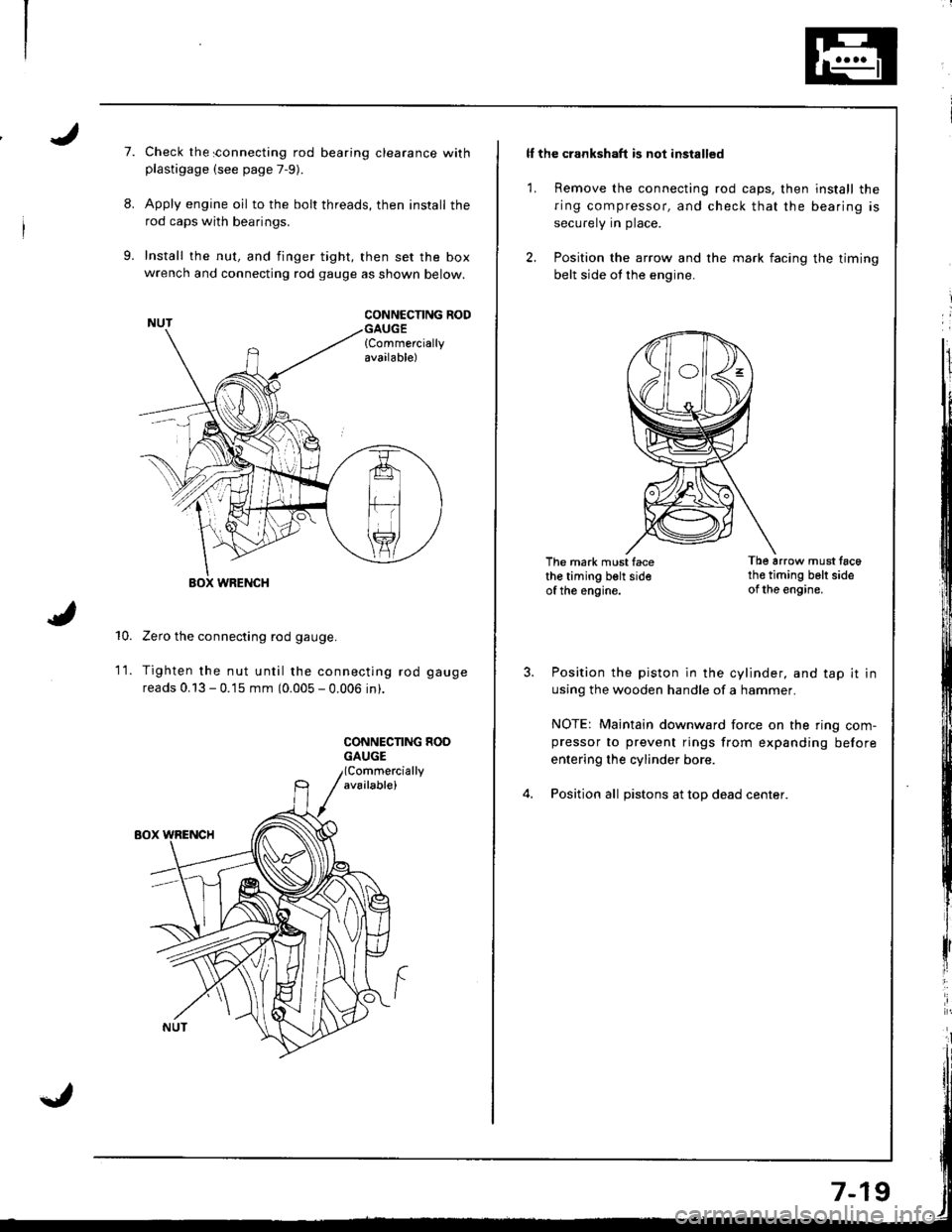
Install the nut, and finger tight, then set the boxwrench and connecting rod gauge as shown below.
CONNCCNNG RODGAUGE{Commerciallyavailable)
10.
WRENCH
Zero the connecting rod gauge.
Tighten the nut until the connecting rod gauge
reads 0.13 - 0.15 mm (0.005 - 0.006 in).
CONNECNNG HOOGAUGE
1t.
ll the crankshaft is not installed
1. Remove the connecting rod caps, then install the
ring compressor, and check that the bearing is
securely in place.
2. Position the arrow and the mark facing the timing
belt side ot the engine.
The mark must facethe timing belt sideof the engine.
Tb6 arrow must tac6th€ timing belt sideof the engine.
Position the piston in the cylinder, and tap it in
using the wooden handle of a hammer.
NOTE: Maintain downward force on the ring com-pressor to prevent rings from expanding before
entering the cylinder bore.
Position all pistons at top dead center.
Page 164 of 1681
Piston Rings
Replacement
Using a ring expander, remove old piston rlngs.
Clean all ring grooves thoroughly.
o Use a squared-ofl broken ring or ring groove
cleaner with blade to fit piston grooves.
. lop ring groove is 1.0 mm (0.039 in) wide, sec
ond groove is 1.2 mm (0.047 in) wide, and oil
ring groove is 2.8 mm (0.110 in) wide.
. File down blade if necessary.
CAUTION: Do not use a wire brush to clean the
ring lands, or cut ring lands deeper with cleaning
tool.
NOTE: lf the piston is to be separated from the con
necting rod, do not install new rings yet.
Install new rings in the proper sequence and posa-
tion (see page 7 21).
Do not use old piston rings.
PISTON RING
End Gap
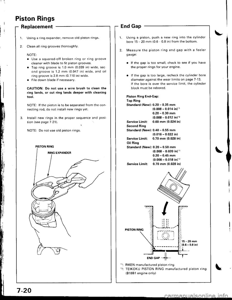
Using a piston, push a new ring into the cvlinder
bore 15 - 20 mm 10.6 0.8 in) f rom the bottom.
2. N,4easure the piston ring end gap with a feeler
gauge:
lf the gap is too small, check to see if you have
the proper rings for your engine.
. lf the gap is too large, recheck the cylinder bore
diameter against the wear limits on page 7-13.
lf the bore is over the service limit, the cylinder
block must be rebored.
Piston Ring End-Gap:
Top Ring
Standard (New):0.20 - 0.35 mm
(0.008 - 0.014 inl'1
0.20 - 0.30 mm
{0.008 - 0.012 in}''�
Service Limit: 0.60 mm {0.024 in)
Second Ring
Standard {New): 0.40 - 0.55 mm
{0.016 - 0.022 inl
Service Limit: 0.70 mm {0.028 inl
Oil Ring
Standard (New): 0.20 - 0.50 mm
10.008 - 0.020 in)'r
0.20 - 0.45 mm
(0.008 - 0.018 in)''�
Service Limit: 0.70 mm (0.028 in)
PISTON RING
15-20mm{0.6 - 0.8 in)
RIKEN manufactured piston ring
TEIKOKU PISTON RING manufactured piston ring
(B 1881 engine only)
Page 166 of 1681
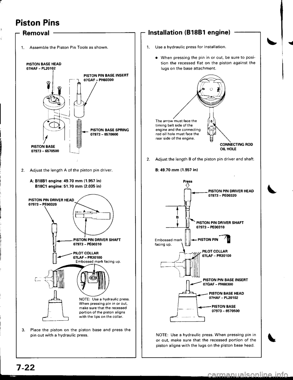
Piston Pins
Removal
1. Assemble the Piston
PISTON BASE HEAD07HAF - P120102
Pin Tools as shown.
PISTON PIN BASE INSERT07GAF - PH6o3q)
PISTON BASE SPRING07973 - 6570600
-rt_
2.
PISTON07973 -
L
PISTON PIN DRIVER SHAFT07973 - PE00310
PILOT COLLARO?LAF - PR3OlOOEmbossed mark facing up.
NOTE: Use a hydraulic press.
When pressing pin in or out,make sure that the recessedportion of the piston alignswith the lips on the collar.
?
Adjusr the length A of the piston pin driver.
A: Bl8Bl engine:49.70 mm (1.957 inl
Bl8Cl engine: 51.70 mm (2.035 inr
PIN DRIVER HEAIPE00320
\
n
\1lll-
|]
n'-"'
Place the piston on the piston base and press the
pin out with a hydraulic press.
Installation (81881 engine)
!{1. Use a hvdraulic Dress lor installation.
When pressing the pin in or out, be sure to posi-
tion the recessed tlat on the piston against the
luqs on the base attachment.
The arrow must face thetiming belt side of theengine and the connectingrod oii hole must face therear side of the engine.
CONNECTING RODOIL HOLE
2. Adjust the length B of the piston pin driver and shaft.
B:49.70 mm (1.957 inl
Prca3
PISTON PIN DRIVER SHAFT07973 - PE00310
Embossed mark
ffi-n"ro"r,"l
PILOT COLLAR07LAF - PR30100
PISTON PIN BASE INSERT07GAF - PH60300
PISTON BASE HEAO07HAF - PL20102
PISTON BASE0?973 - 6570500
NOTE: Use a hydraulic press. When pressing pin in
or out, make sure that the recessed portion of the
piston aligns with the lugs on the piston base head.