Page 1101 of 1681
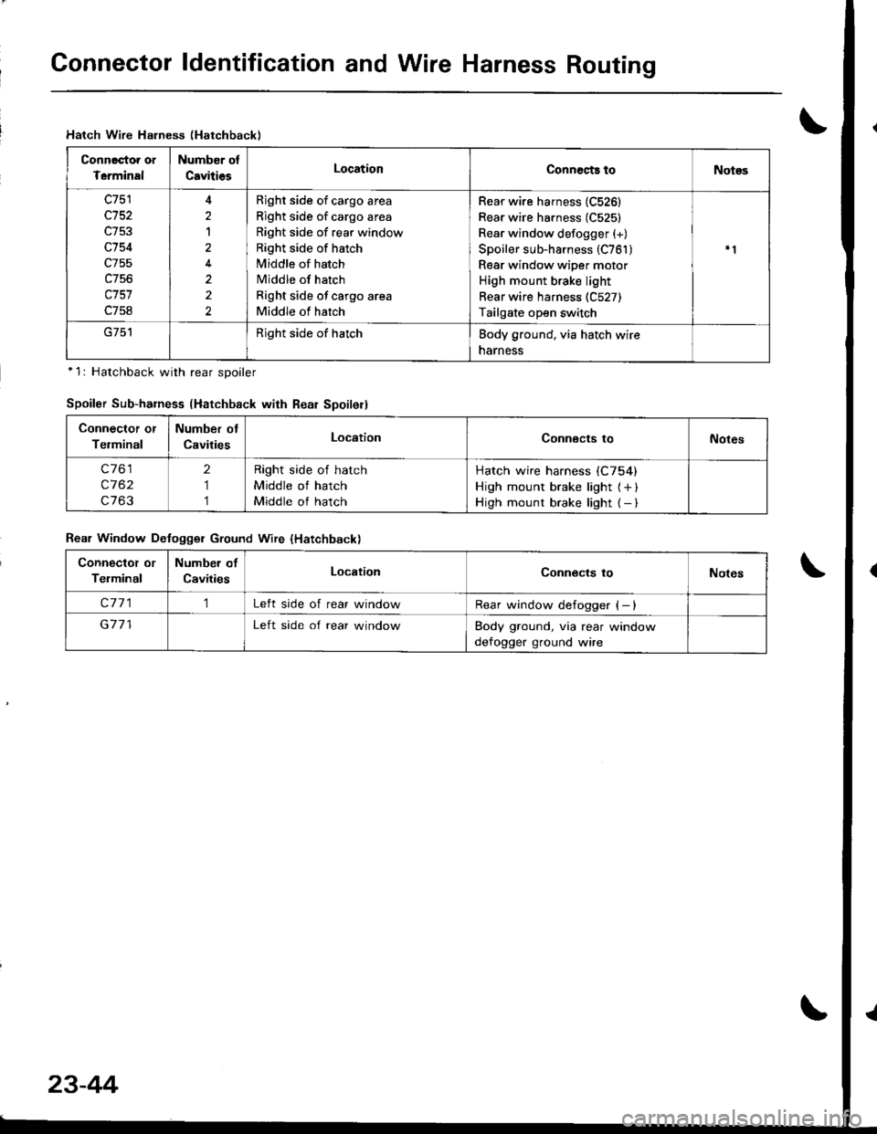
Gonnector ldentification and Wire Harness Routing
Hatch Wire Halness (Hatchback)
Connactoa oa
Tcrminal
Numb€r of
CavitiesLocationConnects toNot€s
c751
c152
c754
c755
c757
c758
2
1
2
2
Bight side of cargo area
Right side of cargo area
Right side of rear window
Right side of hatch
Middle of hatch
Middle of hatch
Right side of cargo area
Middle of hatch
Rear wire harness {C526}
Rear wire harness (C525)
Rear window defogger (+)
Spoiler sub-harness (C761 )Rear window wiper motor
High mount brake light
Rear wire harness (C527)
Tailgate open switch
Right side of hatchBody ground, via hatch wire
narness
*1: Hatchback with rear sDoiler
Spoiler Sub-harness (Hatchback with Rear Spoilell
Connector or
Telminal
Number ot
CavitiesLocationConnects toNotes
c761
c762
c763
2
1
1
Right side of hatch
Middle of hatch
Middle of hatch
Hatch wire harness (C754)
High mount brake light { + )High mount brake light { - )
Rear Window Defogger Ground Wire {Hatchback)
Connectot or
Telminal
Number of
CavitiesLocationConnects toNotes
c7711Left side of rear windowRear window defogger (- )
G711Left side of rear windowBody ground, via rear window
defogger ground wire
23-44
Page 1110 of 1681
J
)1 -
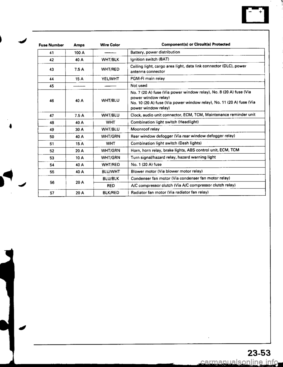
Fuso NumborAmpsWir€ ColorComponent(s) or Circuh(rl Protastcd
41100 ABattery. power distribution
4240AWHT/BLKlgnition switch (BAT)
437.5 AWHT/REDCeiling light, cargo area light, data link connector (DLCl, power
antenna connector
44't5 AYEL/WHTPGM-Fl main relay
45Not used
4640AWHT/8LU
No. 7 (20 A) fuse (Via power window relay), No. 8 (20 A) tuse (Via
power window relay)
No. 10 (20 A) fuse (Via power window relay), No. 11 (20 A) fuse (Via
power window relay)
417.5 AWHT/BLUClock,8udio unit connector, ECM, TCM, Maint€nance reminder unit
4840AWHTCombination light switch (Headlight)
4930AWHT/BLUMoonroof relay
5040AWHT/GRNRear window defogger {Via rear window defogger relay)
51154WHTCombination light switch (Dash lights)
20AWHT/GRNHorn, horn relay, brake lights, AgS control unit, ECM, TCM
10AWHT/GRNTurn signal/hazard relay, hazard warning light
5440AWHT/flEDNo. 1 (20 A) fuse
40ABLU/WHTBlower motor (Via blower motor relsy)
56204BLU/BLKCondenser fan motor (Via condenser {an motor relay)
REDA,/C compressor clutch (via Ay'c comp.essor clutch relay)
57204BLVREDRadiator f8n motor (Via radiator fan relay)
23-53
Page 1111 of 1681
Power
Circuit
Distribution
ldentification
UNDER.HOOO ABSFUSE/RELAY 8OX
ABS OUMP MO'OF CELAY
I Li,z (via ABS lail.sale telay)
L lgS moou aror un r(Va ABS lai.sale retay)
N0.62 (20A)FUSElvia ABS lai-l\sale re ay /
ABS pump motor
ABS conlrol unir (MCK)
ABS con$olunit (PMR)
Hazad warning lightTurn signal/hazard elay(Viaswilch)Horn
BRN/YEL
YEUFED
8LK - Shner molor
BLK/RED
T
G1
GmlG401
ALTERNATORwHriGRN---
WHT/GRN -No rs {7.5A1 V"LL,,r,
_f,-"*
GRNMHT -F ABS conlrollnrt
t- EcM TcM_ &eke ughts
GRN/RED - ECM
*HT,BLK --+ ig|ryJ,itil.* F^r
F UNDEF OASHvlHi.nED -I4 > FUSE FELAY BOXLz {To page 23 59)
YEITWHT - PGM.Flmain retav
T. UNDER.DASHI/HT a_U -l 'l > .uSE RELAV 8OXfro page 23 57)
ClockECM
TCMMainlenance reminder unl
MT/GRN --T Horn relav
-ol- WHTTGRN -l
BRAKE SWITCHION: Pedal depressedl
23-54
Page 1122 of 1681
I "tl
III
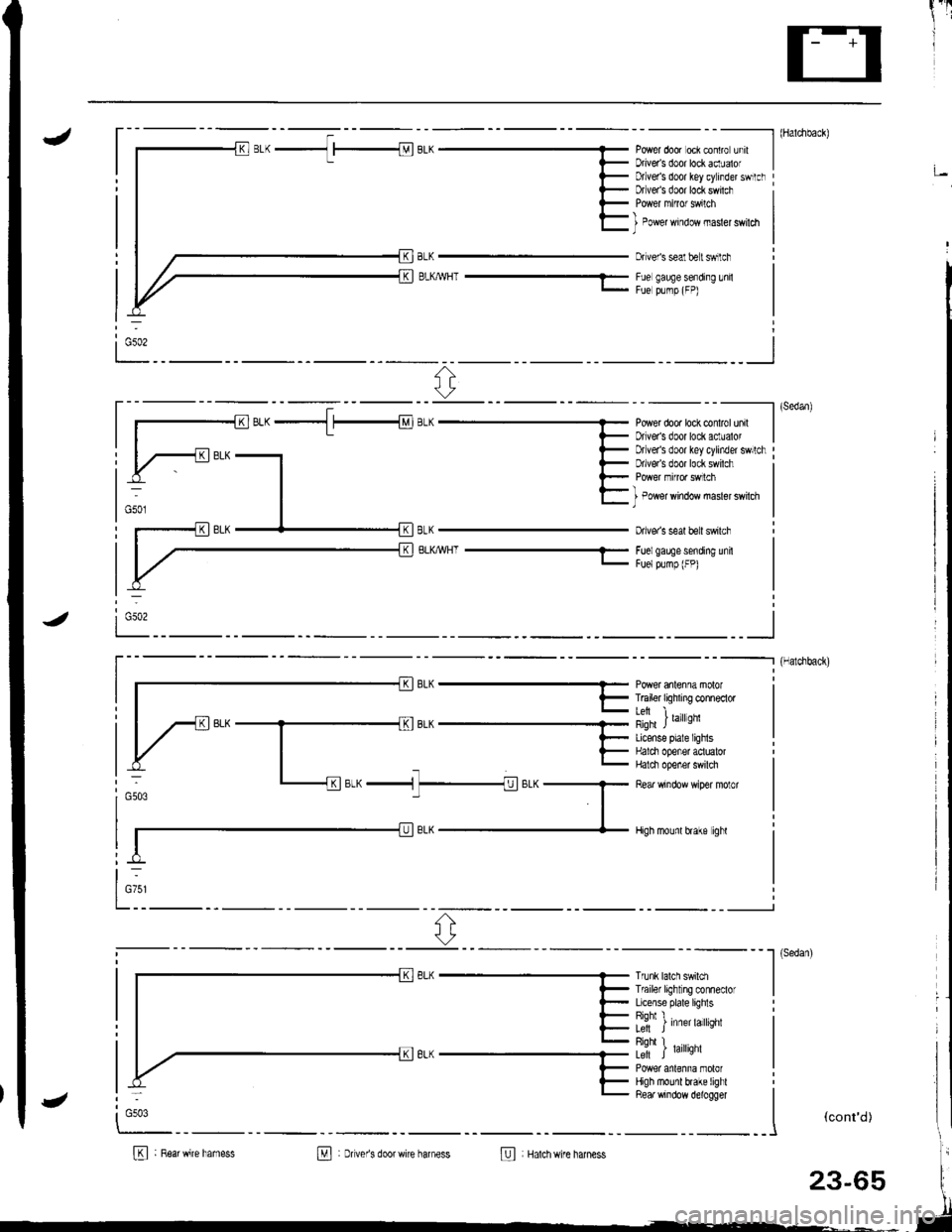
J- - - - --------- l (Haldlback)
Power door oci contro unrt IDriveas door lockaclualof I;Dtlver's door key cylinder swrtclrDfveas door lock swilch
BLKMHT ---1-
I Power window masler swildl)
Dr veis seal belt swilch
Fue gauge sending lnilFue plmp (FP)
ri:
----------l (sedan)
Power dooa lock conlrol unil IDriveas door lock aclualor I
BLKWHT-
Drlver's door key cylinder swllchDrlve/s door lock swilch
I Power window masler swilch)
Dive. s seal beit swilch
Foelgaee sending unitFuelpump (FP)
i Gso2
_ _ _--_______.] {Halchback)
r- || | F T6iler tiqhxng conneclor I
lil i ,",rror,'nqfi JLicense plale lighlsHalci opener aotualorHalci opener swilch
Rear window wiper molor
High mounl hake ighl
otw ^ -n1
t-
l_:1' ^r;-"-1 7_1;.^G503
Trunk lalch swildlTf ailer light ng conneclorLicense plate lighlsRiohl I�L; J Inner larqnr
Riohl I� .Le-ft J raflqnl
High mounl brake lighlRea. window d€logger
I
""*'�
I
(cont'd)
B : R6arwire hamessM : Dver's doorwire harness@ Hatchwire harness
:
G503
23-65
Page 1179 of 1681
I
rIGauge Assembly
BulbLocations
RIGHT TURN SIGNAL INOICATOR LIGHT ('I.4 WI
BRAKE SYSTEM LIGHT I1.4 WI
DOOR-OPEN INDICATOR LIGHT (1.4 WI
*ABS/SRS INOICATOR LIGHT (1.' W)
LOW FUEL INDICATOR I-IGHT I3.4 W)
SEAT BELT REMINDER LIGHT {1.4 WI
HATCH-OPEN INDICATOR LIGHT {1.4 W}: HarchbackTRUNK'OPEN INDICATOR LIcHT (1.4 W): Sedan
+: On the ABS/SRS printed circuit board
LEFT TURN SIGNAL INDICATOR LIGHT (1.4 WI
CHARGING SYSTEM LIGHT {1,4 WI
A/T GEAR POSITION INDICATOR LIGHT (1.'t2 W x 7)
HIGH BEAM INDICATOR LIGHT I1 .4 \A,
LOW ENGINE OIL PRESSUREINDICATOR LIGHT (1.4 W}
MALFUNCTION INDICATOR LAMP(MtLl (1.4 Wl
LIGHTS13.4 W x 3)REMINDER LIGHT I1.4 WI
cRursE LTGHT | 1.4 Wt
23-122
Page 1192 of 1681
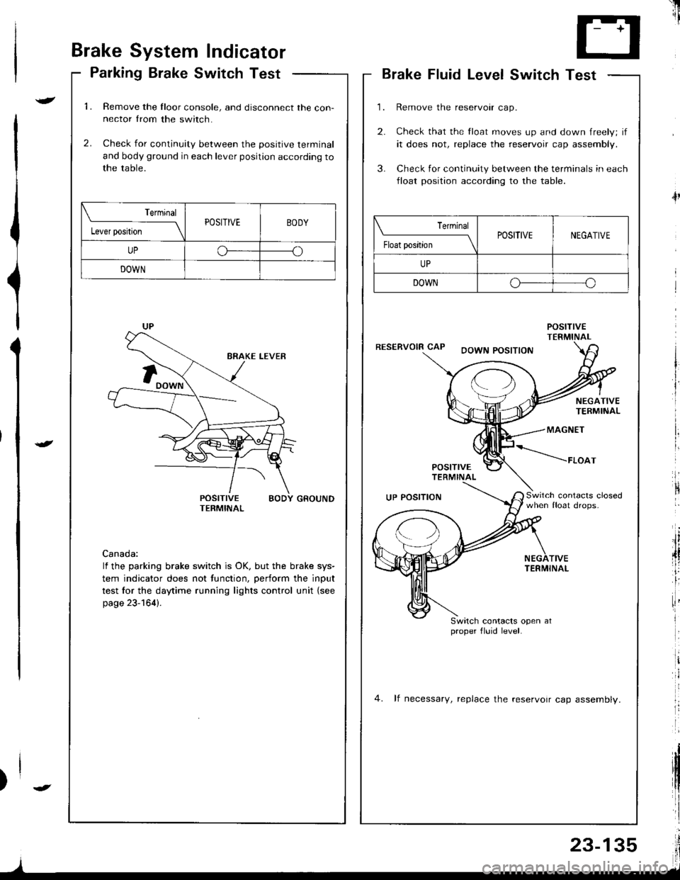
Brake System Indicator
Parking Brake Switch Test
1.Remove the Iloor console, and disconnect the con-nector from the switch.
Check for continuity between the positive terminal
and body ground in each lever position according tothe table.
2.
POSITIVE BODY GROUNDTERMINAL
Canada:
lf the parking brake switch is OK, but the brake sys-
tem indicator does not function, perform the input
test for the daytime running lights control unit {see
page 23-164).
Terminal
l"*rr*ril---ltPOSITIVEBODY
UPoo
DOWN
'il
--r '1i
T- +T
L.J
Brake Fluid LevelSwitch Test
Remove the reservoir cap.
Check that the float moves up and down freely; if
it does not, replace the reservoir cap assembly.
Check for continuity between the terminals in each
lloat position according to the table.
POStnVETERMINALRESERVOIR CAPDOWN POSITION
4l
NEGATIVETERMINAL
MAGNET
POSITTVETERMINAL
*----raoo,
Switch contacrs closedwhen float drops.UP POSITION
TIVETERMINAL
Switch contacts open atproper fluid level.
4. lf necessary, replace the reservoir cap assemblv.
| ermrnal
Float position \POSITIVENEGATIVE
UP
DOWNo--o
I
Page 1200 of 1681
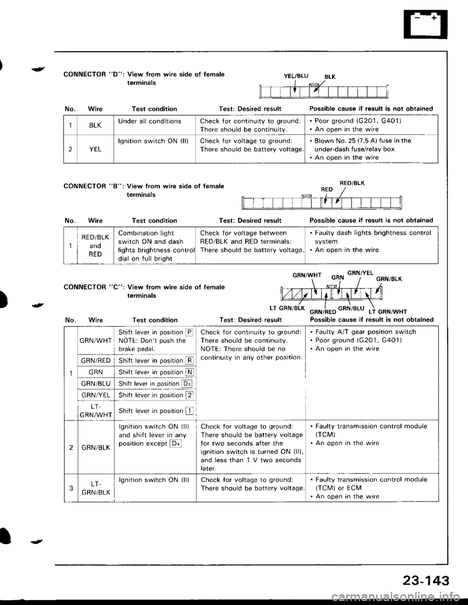
{CONNECTOR "D": View from wire side of lemale
terminalsYEL/BLU
CONNECTOR "8": View from wire side ot female
terminals
No.Wire
No.Wire
Test condition
Test condition
Test condition
Test: Desired result
Test: Desired result
Possible cause il result is not obtained
Possible cause if result is not obtained
Possible cause iI lesult is not obtained
)
CONNECTOR "C": View from wile side ot female
terminals
LT
No.Test: Desired result
1BLKUnderall conditionsCheck {or continuity to ground:
There should be continuity.
Poor ground (G201 , G401)
An open in the wire
2YEL
lgnition switch ON (ll)Check for voltage to groundl
There should be battery voltage
Blown No. 25 (7.5 A) fuse in the
under-dash fuse/relay box
An open in the wire
RED/BLK
1
R E D/BLK
ano
RED
Combination light
switch ON and dash
lights brightness control
dial on full bright
Check for voltage between
RED/BLK and RED terminalsl
There should be battery voltage.
. Faulty dash lights brightness control
system. An open in the wire
1
GRN/WHT
Shifl lever in position @NOTE: Don't push the
brake pedal.
Check {or continuity to ground:
There should be continuity.
NOTE: There should be no
continuity in any other position.
Faulty A/T gear position switch
Poor ground (G201 , G401)
An open in the wire
GRN/RED
GRN
GRN/BLU
GRN/YEL
5nrrI rever In pos[ron ll
shl, b*|' il. p"1,!lN
)nrn rever In posrron url
snt r""-. r p*;ir" tZ-
LT.
GRN/WHTShift lever in position f
2GRN/BLK
lgnition switch ON (ll)
and shift lever in any
position except E
Check for voltage to ground:
There should be battery voltage
lor two seconds after the
ignition switch is turned ON (ll),
and less than 'l V two seconds
later.
. Faulty transmission control module(TCM)
. An open in the wire
3LT-
G RN /BLK
lgnition switch ON (ll)Check lor voltage to ground:
There should be battery voltage.
. Faulty transmission control module
(TCM) or ECM'An open in the wire
23-143
Page 1209 of 1681
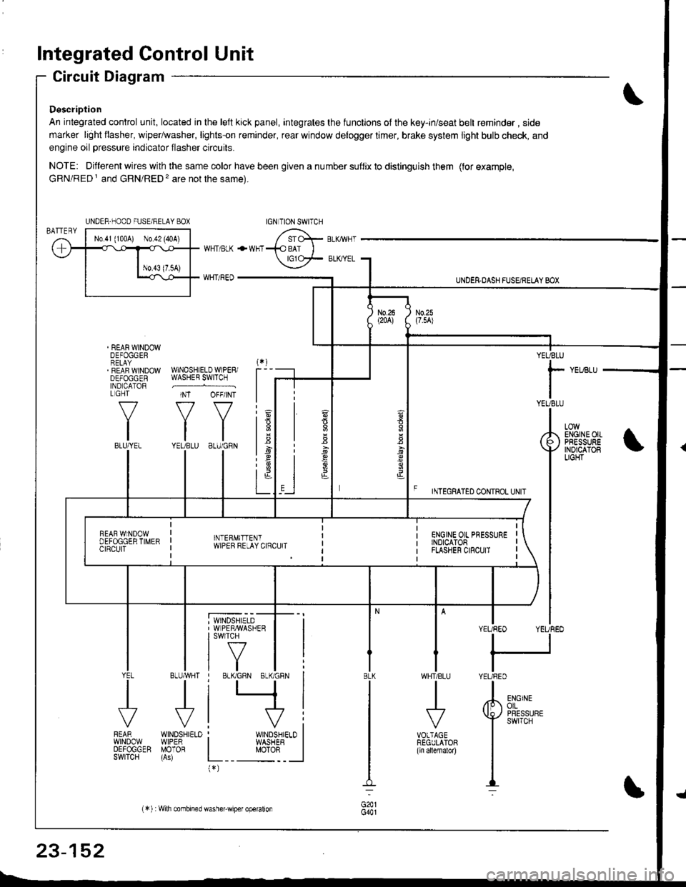
Integrated Control Unit
Circuit Diagram
Description
An integrated control unit, located in lhe left kick panel, integrates the lunctions of the key-in/seat belt r€minder , side
marker light llasher, wiper/washer, lights-on reminder, rear window delogger timer, brake system light bulb check, and
engine oil pressure indicator flasher circuits.
NOTE: Different wires with the same color have been given a nu mber suflix to distinguish them (for example,
GRN/RED I and GRN/RED'� are not the same).
REAR WINDOWDEFOGGERRELAYREAF WINDOWDEFOGGENIND CATORL GHT
f-7
IIBLU/YEL
WHT/ BLK
WHT/ REO
+WHT
WNDSHIELDWIPERiWASHER SWITCH
INT OFF/INT
f7 f7
tltlYEUBLU 8LU/GRN
BLUMHT
J
wtN0sHr€10WIPERMOTOR
UNDER.DASH FUSARETAY BOX
F rmecnlleo counoL ultr
YEUBLU
rYEUBLU
YEUREO YEUREO
tl
IYEURED
LOWENGINEOIIPRESSUREINOICATOBLIGHT
; WINDSHIELD' WIPERMASHERI swlTcH
tf7IVtlYEL
J
FEARwtN00wOEFOGGERSWITCH
WHTIBLU
J
VOTTAGEREGULATOR(ln allernatol)
BLK
G441
ENGINEolLPRESSUREswrTcH
UNDER-NOOO FUSE/RELAY BOX
1.6
:6
t;t-L
i
"'i'- 'i*-
|
I Il
I vi: WINDSHIELO II WASHEB I
L__ "oto: _ __l(*)
n
s
s
,]
23-152
(*) :Wilh combined washer-wiper operalion