1998 HONDA INTEGRA oil cap
[x] Cancel search: oil capPage 543 of 1681

Regulator Valve Body
Disassembly/lnspection /Reassembly
NOTE:
a Clean all parts thoroughly in solvent or carburetor cleaner. and dry with compressed air.
a Blow out all passages.
a Replace valve body as an assembly if any parts are worn or damaged.
a Check all valves for free movement. lf any fail to slide freely, see Valve Body Repair on page 14-121.
1. Hold the regulator spring cap in place while removing the lock bolt. Once the bolt is removed. release the spring
cap slowly.
CAUTION: The regulator sp ng c8p can pop out when the lock bolt is r€moved.
2. Reassembly is in the reverse order of the disassembly procedure.
NOTE:
. Coat all pans with ATF.
a Align the hole in the regulator spring cap with the hole in the valve body, press the spring cap into the body and
tighten the lock bolt.
LOCK BOLT6 x 1.O mm12 N.m 11.2
COOLER CHECK
DOWEL PINS, 2
REGULATOR SPRING CAP
ROLLER
REGULATOR VALVE BODYInspect for wear, scratchesand sconng.
oi.
.. /
,/ i>, ll
,/ "W_-
VALVE SLEEVE
@LOCK-UP CONTROLVALVE
SPRING SPECIFICATIONSUnit of length; mm (in)
No.Spring
Standard {Newl
Wiro Dia.o.D.Froo LongthNo. of Coils
o
@
@
@rA
@
Regulator valve spring A
Regulator valve spring B
Stator reaction spring
Lock-up control valve sprlng
Cooler check valve spring
Torque converter check valve spring
1.8 (0.071)
1.8 (0.071)
4.5lO.177l
0.8 (0.031)
1.0 (0.039)
1.0 (0.039)
14.7 {0.579}*6.0 (0.236)
26.4 (1.039)
6.6 (0.260)
8.4 (0.331)
8.4 (0.331)
87.8 (3.457)
44.0 \1.1321
30.3 (1.1931
41.6 (1.638)
33.8 (1.331)
33.8 (1.331)
to.c
1.92
27.6
8.2
4.2
*: lnside Diameter
, 14-126
!
Page 670 of 1681

Rack Guide AdjustmentFluid Replacement
Check the reservoir at regular intervals, and add fluid as
neceSsary.
CAUTION: Use only Genuine Honda Powel Ste€ring
Fluid-V. Using other fluids such as ATF or othor manu-
laclurer's power ste€ring fluid will damag€ the systom.
SYSTEM CAPACIW:
B18Gl ongine:
1.06lit€r (1.12 US. qt,0.93 lmp.qt)
Excopt 8l8Cl ongino:
1.0 lher (r.06 US. qt.0.88 imp.qtl
at disa$ombly
RESERVOIR CAPACITY:
0.,0 liter {0.42 US. qt, 0.35 lmp.qt}
LEVEL LINE
LEVEL LINE
Raise the reservoir and disconnect the return hose
that goes to the oil cooler.
Connect a hose of suitable diameter to the discon-
nected return hose and put the hose end in a suit-
able container.
CAUTION: Take care not to spill thq fluid on lhe
body and parts. Wipe off any spilled fluid al onc€.
Start the engine. let it run at idle, and turn the steer-
ing wheel from lock-to-lock several times. When
fluid stops running out of the hose, shut off the
engine. Discard the fluid.
2.
RETURN HOSE{From the oilcooler)
4. Reinstallthe return hose on the reservoir.
5. Fill the reservoir to the uDDer level line.
6. Start the engine and run it at fast idle, then turn the
steering from lock-to-lock several times to bleed air
from the system,
7. Recheck the fluid level and add some it necessary.
CAUTION: Do not lill the reservoir boyond thc
upper level line.
J.
4.
NOTE: Perform rack guide adjustment with the wheels
in the straight ahead position.
1. Loosen the rack guide screw locknut with the spe-
cialtool, then loosen the rack guide screw.
Tighten the rack guide screw until it compresses the
spring and seats against the rack guide, then loosen
it.
Retighten ihe rack guide screw to 3.9 N.m (0.4
kgf.m, 2.9 lbi.ft), then back it ofl to specified angle.
Speciliad Roturn Anglo: 20' Max
Tighten th€ locknut while holding the rack guide
screw.
RACK GUIDE SCREW
25Nm{2.5 kgf.m, 18 lbf ft)
LOCKNUT WRENCH. ilo mm079't 6 - SA50001
E
6.
Check for tight or loose steering through the com-
plete turning travel.
Perform following inspections:
. Steering operation (see page 17-18).
a Power assist with car parked.
I
Page 679 of 1681

Steering Column
Inspection
Check the steering column ball bearing and the steer-
ing joint bearings for play and proper movement. ll
there is noise or if there is excessive plav, replace the
ioint or column assembly.
Check the retaining collar tor damage. lf ir is dam'
aged, replace the retaining coilar.
Check the absorbing plates, absorbing plate guides
and sliding capsules for distonion and breakage.
Replace them as an assembly if they are distorted or
DroKen.
ABSORBING PLATE
COLUMN SALL BEANING
IGNITION SWITCHsee section 23.
Move the tilt lever from the loose position to lock
position 3 to 5 times; then measure the tilt lever
preload 10 mm (0.4 in) from the end of the tilt lever.
Preload: 70-90 N {7 -9 kgl, 15-20 lbll
lf the measurement is out of the specification,
adjust the preload using the following procedures.
a. Loosen the tilt lever, and set the steering column
in the neutral position,
b. Remove the 6 mm lock bolt and remove the stop.
c. Adjust the preload by turning the tilt lock bolt left
or right.
d. Pull up the tilt lever to the uppermost position
and install the stop. Check the preload again. lf
the measurement is still out of specification,
repeat the above procedures (a) through (c) to
adjust.
CAUTION: Be carelul not to loosen the lilt lsvel
when installing the stop or tightening the 6 mm
lock bolt.
RETAINING COLLAR
AESORBING PLATE
JOINTBEARINGS
PLASTICINJECTIONS
This pan is attachedto the column bracketwith the plastic iniectaons.
t
SPRING SCALE
TILT LOCK BOLT
17-30
9.8 N.m (1.0 kst.m, 7.2 lblft)
t
{
I
Page 1039 of 1681
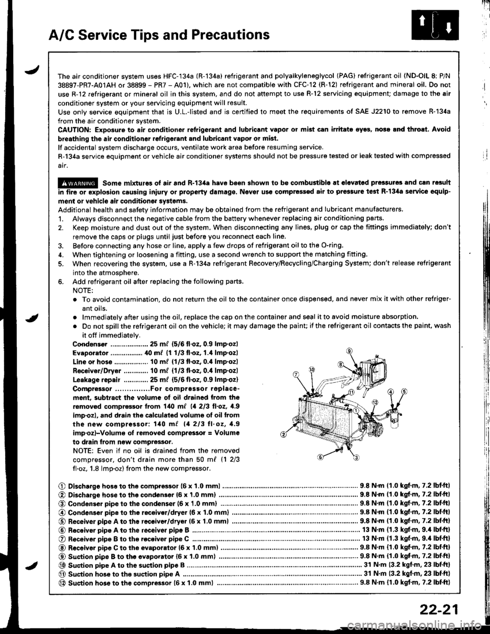
A/C Service Tips and Precautions
The air conditioner system uses HFC-134a (R-134a) refrigerant and polyalkyleneglycol {PAG) refrigerant oil (ND-OlL 8: P/N
38897-PR7-A01AH or 38899 - PR7 - A01), which are not compatible with CFC-12 (R-12) refrigerant and mineral oil. Do not
use R-12 refrigerant or mineral oil in this system. and do not attempt to use R-12 servicing equipment; damage to the air
conditioner system or your servicing equipment will result.
Use only service equipment that is U.L.-listed and is certified to meet the requirements of SAE J2210 to remove R-l34a
from the air conditioner system.
CAUTION: Exposure to air conditioner refrigerant and lubricant vapor ot mist can irritate eyos, nose.nd throat, Avoid
breathing th€ air conditionsr rofrigerant 8nd lubricant vapo. or mist.
lf accidental system discharge occurs, ventilate work area before resuming service.
R-134a service equipment or vehicle air conditioner systems should not be pressure tested or leak tested with comp.essed
atf,
@ some mixtures ol air and R-13i[a have been shown to be combustible at olevat6d pre3sures and cln resuh
in fire or explosion causing iniury or property damage. Nover uso compressed air to prossure te3t R-13,[8 service equip-
ment or vehicle air condition6r systems.
Additional health and safety information may be obtained from the refrigerant and lubricant manufacturers,
1. Always disconnect the negative cable from the battery whenever replacing air conditioning parts.
2. Keep moisture and dust out of the system. When disconnecting any lines. plug or cap the Jittings immediately; don't
remove the caps or plugs until just before you reconnect each line.
3. Before connecting any hose or line, apply a few drops of refrigerant oilto the O-ring,
4. When tightening or loosening a fitting, use a second wrench to support the matching fitting.
5. When recovering the system. use a R-134a refrigerant Recovery/Recycling/Charging System; don't release refrigerant
into the atmosphere.
6. Add refrigerant oil after replacing the following parts.
NOTE:
. To avoid contamination, do not return the oil tothe container once dispensed, and never mix itwith other refriger-
ant oils.
.lmmediatelyafterusingtheoil,replacethecaponthecontainerandseal it to avoid moisture absorption.
. Do notspillthe refrigerant oil onthevehicle; it maydamagethe painu itthe refrigerant oil contacts the paint, wash
it off immediately.
Coodansor ..-.-.-............. 25 mt (5/6 ll.oz. 0.9 lmp.oz)
Evaporator ................. ,[0 m/ (1 1/3 fl.oz, 1.4 lmp.ozl
Line or hoss .................. 10 m? {1/3fl.oz, 0.'l lmp.ozl
Receiver/Dryer ............. 10 m/ (1/3 fl.oz, 0.4 lmp.ozl
Leskage repair .............25 m/ {5/6 fl.oZ, 0.9 lmp.oz)
Compreigor .....,......,..Fo1 comprgssor replace-
ment, subtract the volum€ of oil drained from the
removed comprassor lrom l/t{l m[ (1 213 ll.oz, 1,9
imp'ozl, and drain the calculated volume ot oil from
the new compressor: 140 m/ 11 213 ll.oz, 1.9
imp.oz)-Volum€ oI removed comprsssor = Volum€
to drain trom n€w compressor.
NOTE: Even if no oil is drained from the removed
comDressor, don't drain more than 50 m{ {1 2/3
fl.oz. 1.8 lmp.oz) from the new compressor.
O Dischargo hoso to the compressol (6 x 1.0 mml............................... 9.8 N'm (1.0 kgf.m, 7.2 lbf'ftl
@ Di3charge hose to the condenser {6 x 1,0 mm)
@ Condonser pipe to the condenser (6 x '1.0 mml
9.8 N'm (1.0 kgl.m, 7.2 lbf.ftl
.. 9.8 N.m (1.0 kgf.m,7.2lbl.ltl
@ Condenser pipe to the rec€ivor/dryer (6 x 1.0 mml
O Receiver pipe A to th8 recoiver/dryer (6 x 1.0 mml
@ Receiyar pipe A to lhe receiver pipe B ,...........
O Receiver pipe B to th8 .ocoiver pipe C ............
@ R€ceiver pipe C to the evaporator 16 x 1.0 mm)
@ Suction pipe B to th€ evaporator {6 x 1.0 mm) .......,.
@ Suqtion pipe A to the suction pipe B
O Suction hose to the suction pipe A ...........,.
@ Suction hose to the compressor 16 x 1.0 mml
9.8 N.m (1.0 kgf.m, 7.2 lbf.ftl
9.8 N'm (1.0 kgf.m, 7.2 lbf.fr)
13 N.m (1.3 kgf.m. 9.4 lbf.ft)
13 N.m (1.3 kgf.m,9.'l lbf.ftl
9.8 N.m (1.0 kgt m. 7.2 lbf.ftl
...... 9.8 N.m {1.0 kqf'm, 7.2 lbf.ft)
........ 31 N'm (3.2 kgf.m, 23 lbf.ft)
............ 31 N.m (3.2 kgf.m,23 lbtft)
..................... 9.8 N.m {r.0 kgf.m, 7.2 lbtft)
22-21
Page 1041 of 1681
J
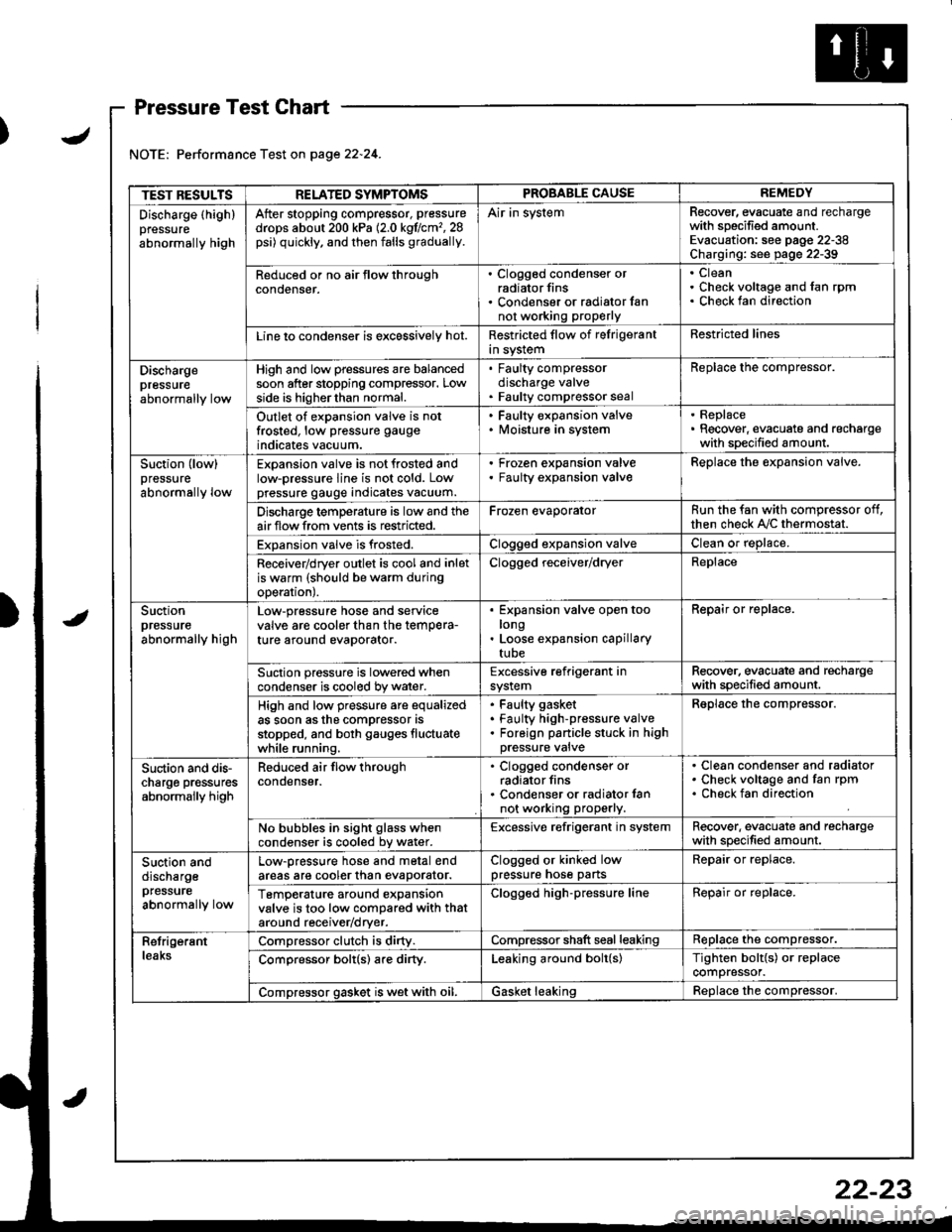
Pressure Test Chart
Performance Test on page 22.24.
TEST RESULTSRELATED SYMPTOMSPROBABLE CAUSEREMEDY
Discharge (highlpressure
abnormally high
After stopping compressor, pressure
drops about 200 kPa (2.0 kgflcm'�,28psi) quickly, and then falls gradually.
Air in systemRecover, evacuate and rechargewith specified amount.Evacuation: see pag€ 22-38Charging: see page 22-39
Reduced or no air tlow throughconoenser.
. Clogged condenser orradiator fins. Condenser or radialor fannot working proPerly
CleanCheck voltage and fan rpmCheck fan direction
Line lo condenser is excessively hot.Restricted flow of felrigerantin systemRestricted lines
Dischargepressureabnormally low
High and low pressures are balancedsoon after stopping compressor. Lowside is higherthan normal.
. Faulty compressordischarge valve. Faulty compressor seal
Replace the compressor.
Outlet of expansion valve is notfrosted, low pressure gauge
indicates vacuum.
. Faulty expansion valve. lvloisture in system
. Replace. Recover, evacuate and rechargewith specified amount.
Suction (low)pressure
abnormally low
Expansion valve is not frosted andlow-pressure line is not cold. Lowpressure gauge indicates vacuum.
Frozen expansion valveFaulty expansion valveReplace the expansion valve.
Discharge temperature is low and theairflow from vents is restricted.Frozen evaporatorRun the fan with compressor off,then check A,/C thermostat.
Expansion valve is frosted.Clogged expansion valveClean or replace.
Receiver/dryer outlet is cool and inletis warm (should be warm duringoperal|onJ.
Clogged receiver/dryerReplace
Suctionpressureabnormally high
Low-pressure hose and seryicevalve are cooler than the temPera-ture around evaporator.
Expansion valve open toolongLoose expansion capillarytube
Repair or replace.
Suction pressure is lowered whencondenser is cooled by water.Excessive refrigerant insystemRecover. evacuate and rechargewith specified amount.
High and low pressure are equalizedas soon asthe compressor asstopped, and both gauges fluctuatewhile running.
Faulty gasket
Faulty high-pressure valveForeign panicle stuck in highpressure valve
Reolace the comDressor.
Suction and dis-charge pr€ssuresabnormally high
Reduced air flow throughcondenser.
. Clogged condenser orradiator fins. Condenser or radiator lannot working properly.
Clean condenser and radiatorCheck voltage and fan rpmCheck fan direction
No bubbles in sight glass whencondenser is cooled bv water.Excessive refrigerant in systemRecover. evacuate and rechargewith specified amount.
Suction anddischargepfessure
abnormally low
Low-pressure hose and metal endareas are cooler than evaDorator.Clogged or kinked lowpressure hose partsRepair or replace.
TemP€rature around expansionvalve is too low compared with thataround receiv€r/dryer.
Clogged high-pressure lineRepair or replace.
RetrigerantleaksCompressor clutch is dirty.Compressor shaft seal leakingReplace the compressor.
Comoressor bolt(s) are dirty.Leaking around bolt(s)Tighten bolt{s) or replacecompressor.
Compressor gasket is wet with oil.Gasket leakingReolace the comoressor.
22-23
Page 1044 of 1681
Evaporator
Replacement
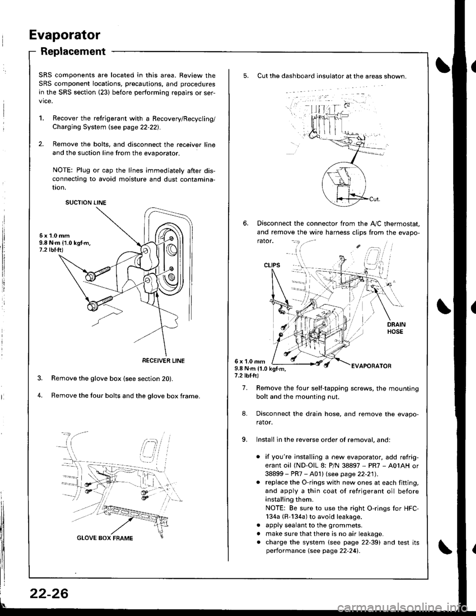
Cut the dashboard insulato. at the areas shown.
Disconnect the connector from the A,,/C thermostat.
and remove the wire harness clips from the evapo-
rator.
6 x 1.0 rnm9.8 N.m 11.0 kgf.m,7.2 tbl.ft)
EVAPOBATOB
7. Remove the four self-tapping screws. the mounting
bolt and the mounting nut.
8. Disconnect the drain hose, and remove the evapo-
rator.
9, Install in the reverse order of removal, and:
. if you're installing a new evaporator, add refrig-
erant oil (ND-OlL 8: PiN 38897 - PR7 - A0IAH or
38899 - PR7 - A0 I I lsee page 22-21) .. replace the O-rings with new ones at each fitting,
and apply a thin coat of refrigerant oil before
installing them.
NOTE: Be sure to use the right O-rings tor HFC-
134a (R-134a) to avoid leakage.
. apply sealant to the grommets.
. make sure that there is no air leakage.. charge the system (see page 22-39) and test itsperformance {see page 22-24l�.
CLIPS
SRS components are located in this area. Review the
SRS component locations, precautions, and procedures
in the SRS section {23) before performing repairs or ser-
vice.
1. Recover the retrigerant with a Recovery/Recycling/
Charging System \see page 22-221.
2. Remove the bolts, and disconnect the receiver line
and the suction line from the evaporator.
NOTE: Plug or cap the lines immediately after dis-
connecting to avoid moisture and dust contamina-
UOn.
6x1.0mm9.8 N.m 11.0 kgf.m,1.2 tbi.ft)
Remove the glove box (see section 20).
Remove the four bolts and the glove box frame.4.
SUCTION LINE
RECEIVER LINE
22-26
Page 1045 of 1681
J
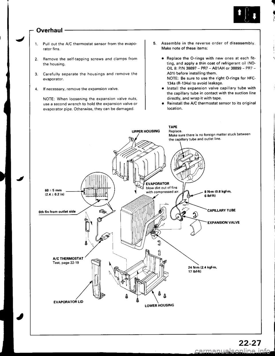
Overhaul
Pull out the A,/C thermostat sensor from the evapo-
rator fins.
t
I
ir
I
Remove the self-tapping screws and clamps from
the housing.
3. Carefully separate the housings and remove the
evaporator.
4. lf necessary. remove the expansion valve.
NOTE: When loosening the expansion valve nuts,
use a second wrench to hold the expansion valve or
evaporator pipe. Otherwise, they can be damaged.
Assemble in the reverse order of disassembly.
Make note ot these items:
Replace the O-rings with new ones at each fit-
ting, and apply a thin cost of retrigerant oil (ND-
OIL 8: P/N 38897 - PR7 - A01AH or 38899 - PR7 -
A01) before installing them.
NOTE: Be sure to use the right O-rings for HFC-
134a (R-134a) to avoid leakage.
Install the expansion valve capillary tube with
the capillary tube in contact with the suction line
directly, and wrap it with tape.
Reinstall the Ay'C thermostat sensor to its original
location.
TAPEReplace.Make sure there is no foreign matter stuck between
tEVAPORATORblow dirt out of tinswith compressed alr'8 N.m {0.8 kgt'm.6 rbf.ftl
CAPILLARY TUBE
EXPANSION VALVE
24 N.m (2.{ kgtm.17 rbf.ftl
UPPER HOUSING
%
6th tin f.om outlet sido
A/C THERMOSTATTest, page 22'19
EVAPORATOR LID
22-27
Page 1049 of 1681
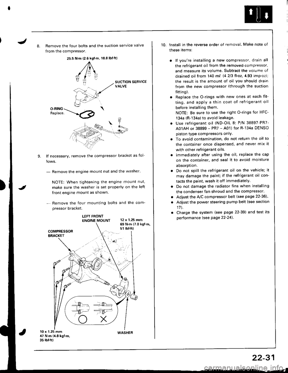
J8. Remove the four bolts and the suction servtce valve
from the compressor.
25.s18.8 tbf.ft)N.m {2.6 kgt.m,
A\
-/ l=\'zI
i:-
9.
SUCTION SERVICEVALVE
O-RING \Benrace. --'.l4p
lf necessary, remove the compressor bracket as fol
- Remove the engine mount nut and the washer'
NOTE: When tightening the engane mount nut,
make sure the washer is set properly on the left
front engine mount as shown.
- Remove the four mounting bolts and the com-
pressor bracket.
LEFT FRONTENGTNE MOUNT 12 x 1.25 mm
I
69 N.m {7.0 kg{.m.s1 rbt.ft)
10 x 1.25 mm47 N.m (4.8 kgf.m.35 rbf.ftt
10. lnstall in the reverse order of removal. Make note of
these rtems:
) lf you're installing a new compressor, drain all
the refrigerant oil from the removed compressor,
and measure its volume, Subtract the volume of
drained oil from 140 m{ 14 2/3ll.oz,4.93 imp.oz);
the result is the amount of oil you should drain
from the new compressor (through the suction
{itting).
r Replace the O-rings with new ones at each fit-
ting, and apply a thin coat of refrigerant oil
before installing them.
NOTE: Be sure to use the right O-rings for HFC-'t34a (R-134a) to avoid leakage.
. use refrigerant oil (ND-OlL 8: P/N 38897 PR7-
A0IAH or 38899 - PR7 - A01) for R-'134a DENSO
piston type compressors onlY.
. To avoid contamination, do not return the oil to
the container once dispensed, and never mix it
with other refrigerant oils.
. lmmediately after using the oil, replace the cap
on the container, and seal it to avoid moisture
aDsorDt|on.
. Do not spill the refrigerant oil on the vehicle; it
may damage the paint; if the refrigerant oil con-
tacts the Daint, wash it off immediately.
. Do not damage the radiator fins when installing
the condenser fan shroud and the compressor.
. Adjust the Ay'C compressoi belt {see page 22-36J
. Adjust the power steering pump belt (see section
17J.
. Charge the system (see page 22-39) and test its
performance {see Page 22-24).
WASHER
22-31