1998 HONDA INTEGRA oil cap
[x] Cancel search: oil capPage 1052 of 1681
Compressor
a
a
Clutch Overhaul (cont'dl
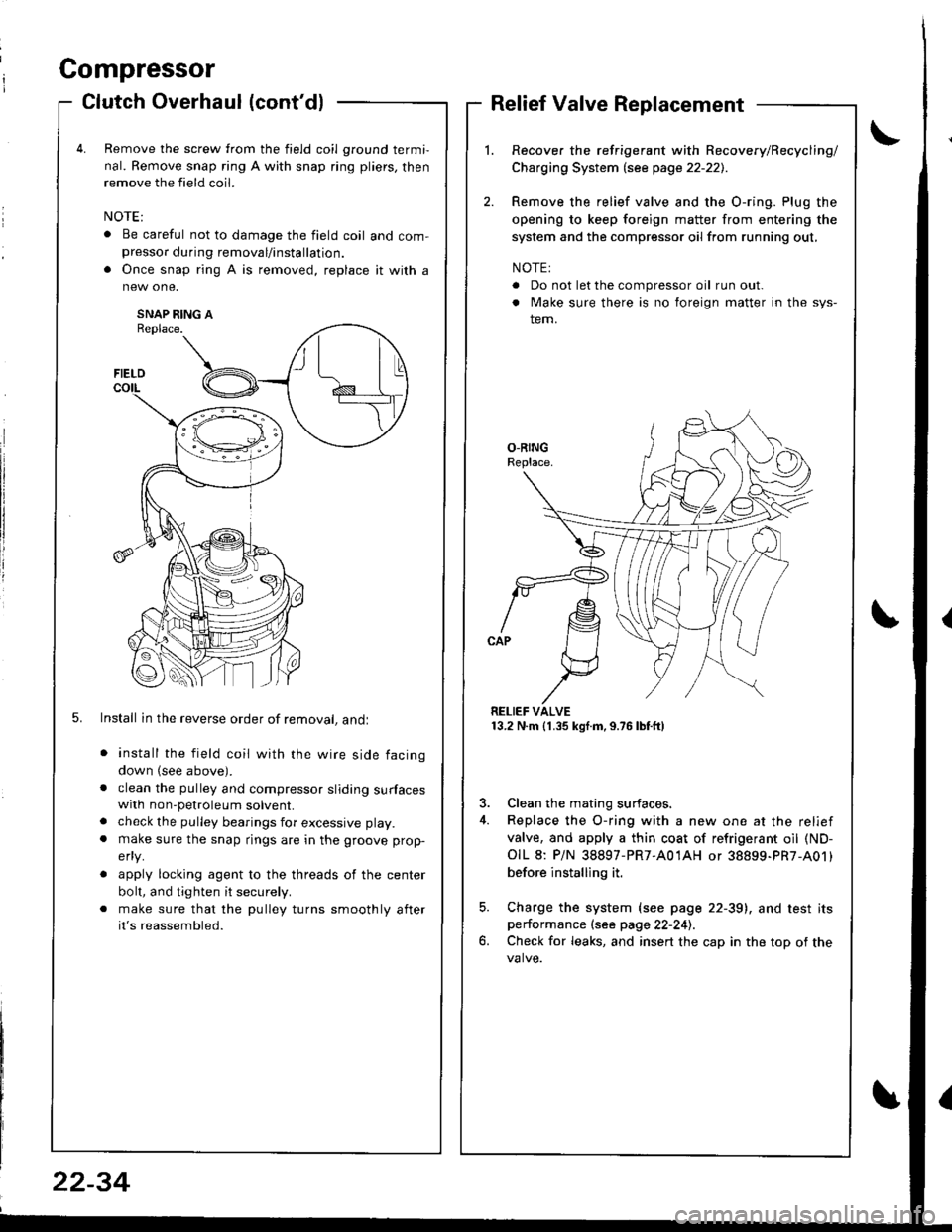
Remove the screw from the field coil ground termi,
nal. Remove snap ring A with snap ring pliers, then
remove the field coil.
. Be careful not to damage the field coil and com-presso. during removal/installation.
. Once snap ring A is removed, replace it with a
SNAP RING AReplace.
5. Install in the reverse order of removal, andl
install the field coil with the wire side facing
down (see above).
clean the pulley and compressor sliding surfaceswith non-petroleum solvent.
check the pulley bearings for excessive play.
make sure the snap rings are in the groove prop-
efly.
apply locking agent to the threads of the center
bolt, and tighten it securely.
make sure that the pulley turns smoothly after
it's reassembled.
Relief Valve Replacement
Recover the refrigerant with Recovery/Recycling/
Charging System lsee page 22-221.
Remove the relief valve and the O-ring. Plug the
opening to keep foreign matter from entering the
system and the compressor oil from running out,
NOTE:
. Do not let the compressor oil run out.
. Make sure there is no foreign matter in the sys-
tem.
RELIEF VALVE13.2 N.m (1.35 kgf.m,9.76lbtft)
3. Clean the mating surfaces.
4. Replace the O-ring with a new one at the relief
valve, and apply a thin coat of refrigerant oil (ND-
OIL 8: P/N 38897-PR7-A01AH or 38899-PR7-A01)
before installing it.
5. Charge the system (see page 22-39), and test itsperformance (see page 22-241.
6. Check for leaks, and insert the cap in the top of the
FIELD
t\I lu
B _t_:---\-lr
\,/
22-34
Page 1055 of 1681
Condenser
J
Replacement
RADIATOR UPPERMOUNT BRACKETS
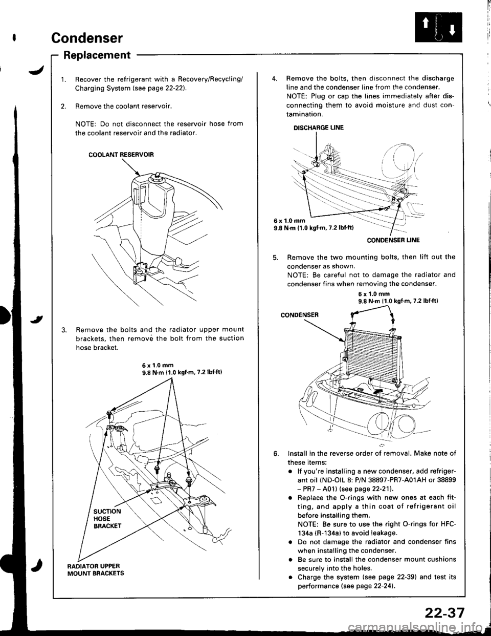
Recover the refrigerant with a Recovery/Recycling/
Charging System lsee page 22-221.
Remove the coolant reservoir.
NOTE: Do not disconnect the reservoir hose from
the coolant reservoir and the radiator.
Remove the bolts and the radiator upper mount
brackets. then remov6 the boll from the suction
hose bracket.
COOLANT RESERVOIR
6x1.0mm9.8 N'm 11.0 kgf'm, ?.2lbf'ft)
4. Remove the bolts, then disconnect the discharge
line and the condenser line from the condenser.
NOTE: Plug or cap the lines immediately after dis-
connecting them to avoid moisture and dust con'
tamination.
DISCHARGE LINE
6x1.0mm9.8 N.m {1.0 kgj'm, 7.2 lbl'ft)
5. Remove the two mounting bolts, then lift out the
condenser as shown.
NOTE: Be careful not to damage the radiator and
condenser fins when removing the condenser.
6x1.0mm9.8 N m 11.0 kgf m, 7.2 lbf ft)
lnstall in the reverse order of removal. Make note of
these items;
. lf you're instslling a new condenser, add refriger-
ant oil (ND-olL 8: P/N 38897-PR7-A01AH or 38899- PR7 - A01) (see page 22-211.
. Replace the O-rings with new ones at each fit-
ting, and apply a thin coat of refrigerant oil
before installing them.
NOTE: Be sure to use the right O-rings for HFC-
134a (R-1344) to avoid leakage.
a Do not damage the radiator and condenser fins
when installing the condenser.
o Be sure to install the condenser mount cushions
securely into the holes.
. Charge the system {see page 22-39) and test its
performance (see page 22-241.
CONOENSER LINE
22-37
Page 1057 of 1681
I
I
ChargingLeak Test
Use only service equipment that is U.L.-listed and is cer-
tified to meet the requirements of SAE J2210 to remove
HFC-134a (R-134a) from the air conditioner system.
CAUTION: Exposure to air conditioner refrig6rant and
lubricant vapol or mist can irritate eyes. nose and
throat. Avoid broating the air conditione. relrigerant
and lubricant vapor o; mist.
lf accidental system discharge occurs, ventilate work
area before resuming service.
R-134a service equipment or vehicle air conditioner sys-
tems should not be pressure tested or leak tested with
compressed air.
@ some mixtures of air and R-1348 have
been shown to be combustible at €levat€d pre3sures
and can rosult in fire or explosion causing iniury or
property damage. Never use compressed air to pressure
test R-134a s€rvics oquipment or vehicle air conditioner
Systems.
Additional health and safety information may be
obtained from the refrigerant and lubricant manufac-
rures.
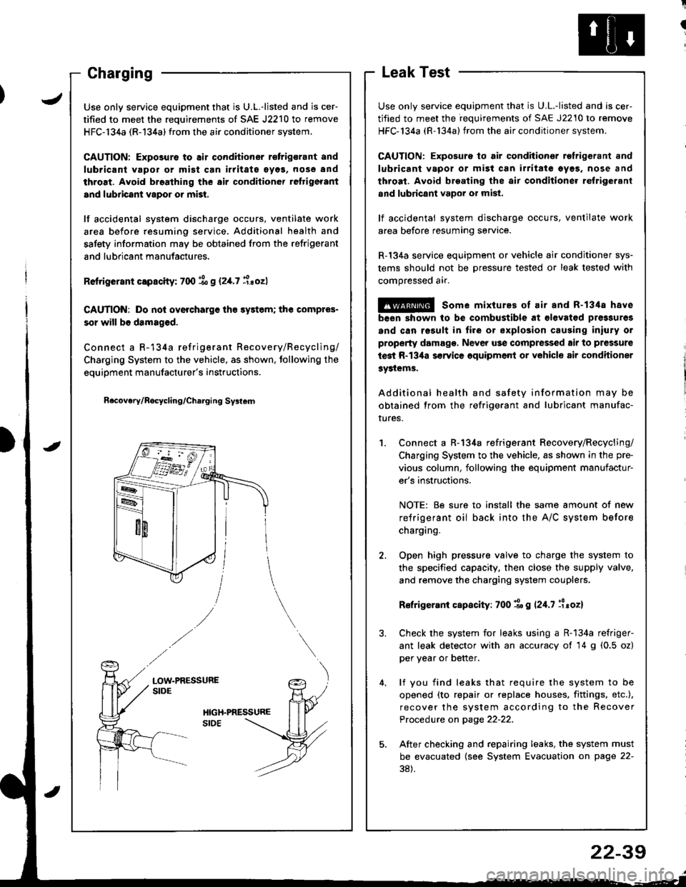
Connect a R-134a refrigerant Recovery/Recycling/
Charging System to the vehicle, as shown in the pre-
vious column, following the equipment manufactur-
er's instructions.
NOTE: Be sure to install the same amount of new
refrigerant oil back into the A/C system before
charging.
Open high pressure valve to charge the system to
the specified capacity, then close the supply valve,
and remove the charging system couplers.
R€frigerani capacity: 700 1o g 124.7 llroz)
Check the system for leaks using a R-134a refriger-
ant leak detector with an accuracy of 14 g (0.5 oz)
per year or better.
lf you find leaks that require the system to be
opened (to repair or replace houses. fittings, etc.),
recover the system according to the Recover
Procedure on page 22-22.
After checking and repairing leaks, the system must
be evacuated (see System Evacuation on page 22-
38).
JUse only service equipment that is U.L.-listed and is cer-
tified to meet the requirements of SAE J2210 to remove
HFC-134a (R-134a) from the air conditioner system.
CAUTION: Exposure to air conditioner r€frigsrant and
lubricant vapol or mist can irritate eyos, nose and
throat. Avoid broathing the air conditioner reftigerant
and lubricant vapor or mist.
lf accidental system discharge occurs, ventilate work
area before resuming service. Additional health and
safety information may be obtained from the refrigerant
and lubricant manufactures.
Retrigerant capscity: 700 % g (2,[.7 i.sozl
CAUTION: Do nol overcharge tho sy3tem; the compres-
sor will b6 damaged.
Connect a R-134a refrigerant Recovery/Recycling/
Charging System to the vehicle, as shown. tollowing the
equipment manufacturer's instructions.
n6covery/Rocycling/Charging Svslem
LOW-PRESSURESIDE
22-39
Page 1153 of 1681
lgnitionSystem
Coil TestlgnitionlgnitionCoilReplacement
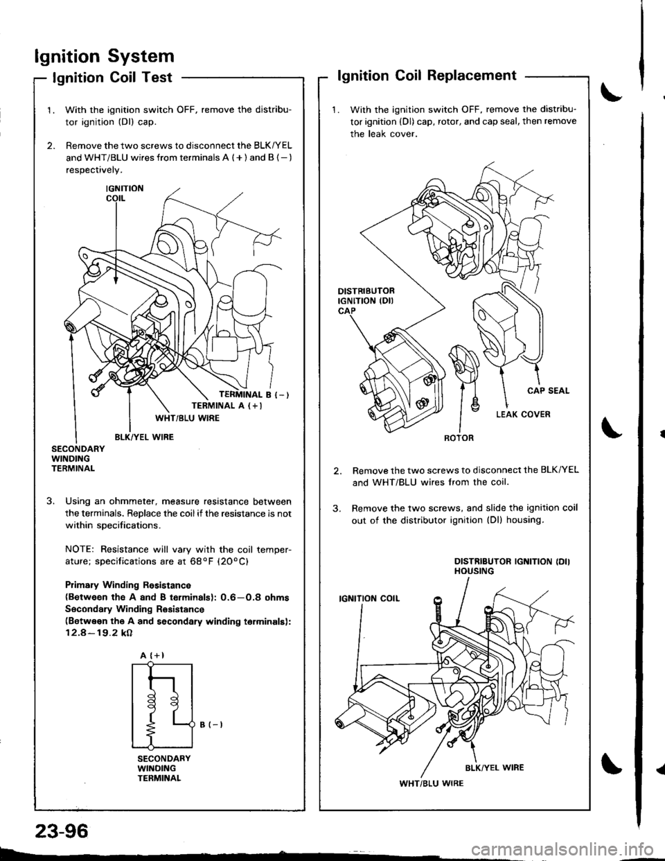
1. With the ignition switch OFF, remove the distribu-
tor ignition (Dl) cap, rotor, and cap seal, then remove
the leak cover.
Remove the two screws to disconnect the BLK/YEL
and WHT/BLU wires lrom the coil.
Remove the two screws, and slide the ignition coil
out of the distributor ignition (Dl) housing.
DISTRIBUTOR IGNITION {DIIHOUSING
ROTOR
WHT/BLU WIRE
2.
1.With the ignition switch OFF, remove the distribu-
tor ignition (Dl) cap.
Remove the two screws to disconnect the BLK/YEL
and WHT/BLU wi.es from terminals A ( + ) and B {- )
respectively.
SECONDARYWINDINGTERMINAL
3. Using an ohmmeter, measure resistance between
the terminals. ReDlace the coilif the resistance is not
within soecifications.
NOTE: Resistance will vary with the coil temper-
ature; specifications are at 68oF (20oC)
Plimary Winding Rssistance(Between th€ A 8nd B torminalsl: 0.6-O,8 ohms
Socondary Winding Resistance(Betwe€n the A and secondary winding torminalsl:
12.4-19.2 kA
B (-t
SECONDARYWllrlDlNGTENMINAL
TERMINAL A (+I
A {+}
{
t
l
tl
t9
t
L--
23-96
Page 1154 of 1681
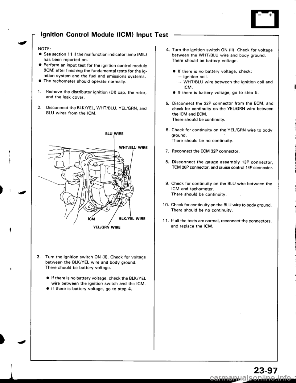
lgnition Control Module (lCM) Input Test
NOTE:
a See section 1 1 if the malfunction indicator lamp (MlLl
has been reported on.a Perform an input test for the ignition control module(lCM) after finishing the fundamental tests for the ig-nition system and the fuel and emissions systems.a The tachometer should operate normally.
1. Remove the distributo. ignition (Dl) cap, the rotor,and the leak cover.
2. Disconnect the BLK/YEL, WHT/BLU, YEL/GRN, andBLU wires from the lCM.
3. Turn the ignition switch ON {ll}. Check for voltage
between the BLK/YEL wire and body ground.
There should be battery voltage.
a lf there is no battery voltage, check the BLKiYEL
wire between the ignition switch and the lCM.a It there is battery voltage, go to step 4,
)
I
)
BLU WIRE
YEL/GRN I,\'IRE
4. Turn the ignition switch ON (ll). Check for voltage
between the WHT/BLU wire and body ground.
There should be battery voltage.
a lf there is no battery voltage, check:- ignition coil.- WHT/BLU wire between the ignition coil and
tcM.
a lf there is battery voltage, go to step 5.
5. Disconnect the 32P connector from the ECM, and
check for continuity on the YEUGRN wire between
the ICM and ECM.
There should be continuity.
6. Check for continuity on the YEL/GRN wire to bodygrouno.
There should be no continuity.
7.Reconnect the ECM 32P connector.
Disconnect the gauge assembly 13P connector,
TCM 26P connector, and cruise control l4P connector.
9. Check for continuity on the BLU wire between the
ICM and tachometer.
There should be continuity.
'10. Check for continuity on the BLU wire to body ground.
There should be no continuity.
1 1 . lf all the tests are normal, reconnect the connectors,
and replace the lCM.
23-97
/i
Page 1647 of 1681
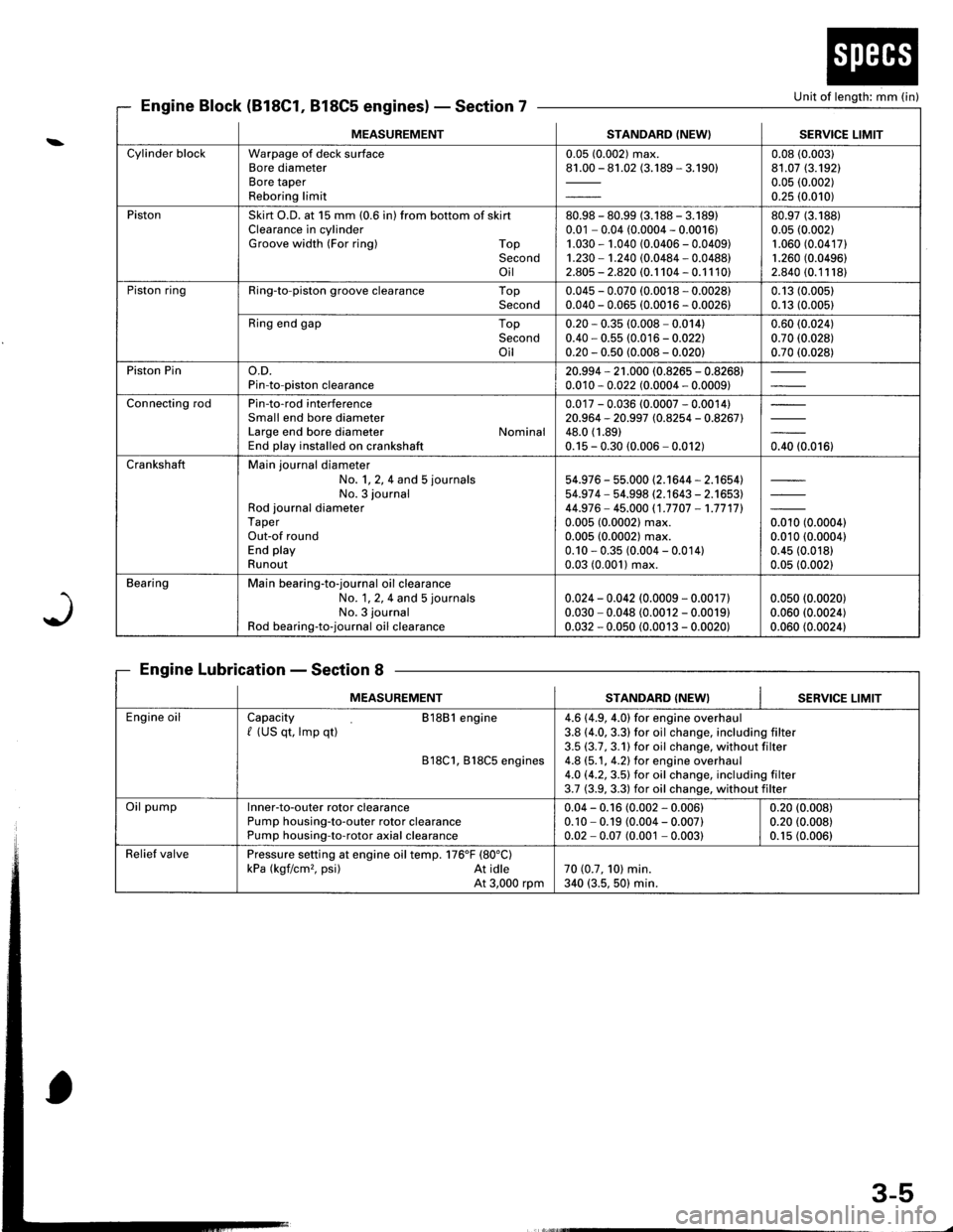
Unit of length: mm (in}
J
Engine Block (818C1, 818C5 engines)Section 7
Engine LubricationSection 8
MEASUREMENTSTANDARD (NEW} I SERVICE LIMIT
Cylinder blockWarpage of deck surfaceBore diameterBore taperReboring limit
0.05 (0.002) max.81.00 - 81.02 (3.189 - 3.190)0.08 (0.003)
81.07 (3.192)
0.05 (0.002)
0.25 (0.010)
PistonSkirt O.D. at 15 mm (0.6 in) from bottom of skirtClearance in cylinderGroove width (For ring) TopSecondoil
80.98 - 80.99 (3.188 - 3.18910.01 - 0.04 (0.0004 - 0.0016)1.030 - 1.040 (0.0406 - 0.0409)1.230 - 1.240 (0.0484 - 0.0488)2.805 - 2.820 (0.1 104 - 0.1 1 10)
80.97 (3.188)
0.05 (0.002)
1.060 (0.04171
1.260 (0.0496)
2.840 (0.11181
Piston ringRing-to-piston groove clearance TopSecond0.045 - 0.070 (0.0018 - 0.0028)0.040 - 0.065 (0.0016 - 0.0026)0.13 (0.005)
0.13 (0.005)
Ring end gap TopSecondoil
0.20 * 0.35 (0.008 - 0.014)0.40 - 0.55 (0.016 - 0.022)0.20 - 0.50 (0.008 - 0.020)
0.60 (0.024)
0.70 (0.028)
0.70 (0.028)
Piston Pino.D.Pin-to-piston clearance20.994 - 21 .000 (0.8265 - 0.8268)0.010 - 0.022 (0.0004 - 0.0009)
Connecting rodPin-to-rod interferenceSmall end bore diameterLarge end bore diameter NominalEnd play installed on crankshaft
0.017 - 0.036 (0.0007 - 0.0014)20.964 - 20.997 (0.8254 - 0.8267)48.0 (1.89)
0.15 - 0.30 (0.006 - 0.012)0.40 (0.016)
CrankshaftMain journal diameterNo. 1, 2, 4 and 5 journals
No. 3 journalRod journal diameterTaperOut-of roundEnd playRunout
54.976 - 55.000 (2.1644 - 2.1654)54.97 4 - 54.998 (2.1643 - 2.1653)44.976- 45.000 (1.7707 -1.7717l.
0.005 (0.0002) max.0.005 (0.0002) max.0.10 - 0.35 (0.004 - 0.014)0.03 (0.001) max.
orro to.ooool0.010 (0.0004)
0.45 (0.018)
0.05 (0.002)
BearingMain bearing-to-journal oil clearanceNo. 1, 2, 4 and 5 journals
No. 3 journal
Rod bearing-to-journal oil clearance
0.024 - 0.042 (0.0009 - 0.0017)0.030 - 0.048 (0.0012 - 0.0019)0.032 - 0.050 (0.0013 - 0.0020)
0.050 (0.0020)
0.060 (0.0024)
0.060 (0.0024)
MEASUREMENTSTANDARD (NEW}SERVICE LIMIT
Engine oilCapacity 81881 engine/ (US qt, lmp qt)
818C1, B18C5 engines
4.6 (4.9, 4.0) for engine overhaul3.8 (4.0, 3.3) for oil change, including filter3.5 (3.7,3.1)for oil change, without filter4.8 (5.1, 4.2) for engine overhaul4.O (4.2,3.5) for oil change. including filter3.7 (3.9, 3.3) for oil change, without filter
Oil pumplnner-to-outer rotor clearancePump housing-to-outer rotor clearancePump housing-to-rotor axial clearance
0.04 - 0.16 (0.002 - 0.006)0.10 - 0.19 (0.004 - 0.007)0.02 - 0.07 (0.001 - 0.003)
0.20 (0.008)
0.20 (0.008)
0.1s (0.006)
Relief valvePressure setting at engine oil temp. 176'F (80"C)
kPa (kgf/cm,. psi) At idleAt 3,000 rpm70 (0.7, 101 min.340 (3.5, 50) min.
3-5
Page 1649 of 1681
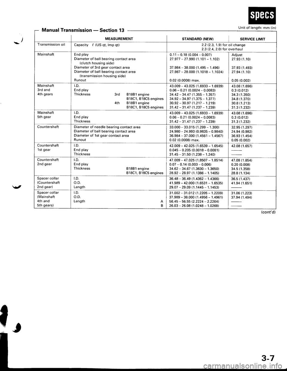
Unit of length: mm (in)Manual TransmissionSection 13
_/
/
MEASUREMENTSTANDARD (NEW}SEBVICE LIMIT
Transmission oilCapacity / (US qt, lmp qt)2.2 12.3, 1.9) for oil change2.3 12.4,2.0) for overhaul
MainshaftEnd playDiameter of ball bearing contact area(clutch housing side)Diameter of 3rd gear contact areaDiameter of ball bearing contact area(transmission housing side)Runout
0.1 1 - 0.18 (0.004 - 0.007)27 .977 - 27.990 (1 .101 - 1.102]|
37.984 - 38.000 (1.495 - 1.496)27.987 - 28.000 (1.1018 - 1.1024l.
0.02 (0.0008) max.
Adiust27 .93 (1.101
37.93 (1 .493)27 .94 11.101
0.05 (0.002)
Mainshaft3rd and4th gears
LD.End playThickness 3rd 81881 engine818C1, B18C5 engines4th 81881 engine818C1, 818C5 engines
43.009 - 43.025 (1 .6933 - 1 .(0.06 - 0.21 (0.0024 - 0.0083)34.42 - 34.47 (1 .355 - 1.357)34.92 - 34.97 (1.37 5 -'�t.377 )30.92 - 30.97 (1.2't7 -'�t.219)
31.42 - 31.47 n.237 - 1.239)
i939)43.0t0.3 ((
34.334.830.831 .3
(1.696)
.01211.350)1.370)1.21311.2321
Mainshaftsth geart.D.End playTh ickness
43.009 - 43.025 (1.6933 - 1.6939)0.06 - 0.21 (0.0024 - 0.0083)31 .42 - 31 .47 11 .237 - 1.2391
43.08 (1.696)
0.3 (0.012)
31.3 11.2321
CountershaftDiameter of needle bearing contact areaDiameter of ball bearing contact areaDiameter of 1st gear contact areaRunout
33.000 - 33.015 (1 .299 - 1 .300)24.980 - 24.993 (0.9835 - 0.9840)36.984 - 37.000 (1.4561 - 1.456710.02 (0.0008) max.
32.95 (1.2971
24.94 (0.982)
36.93 (1 .454)0.05 (0.002)
Countershaft1 st geart.D.End playTh ickness
42.009 - 42.025 (1.6539 - 1.6545)0.045 - 0.205 (0.0018 - 0.0081)31.45 - 31 .50 (1.238 - 1.240)
42.08 (1.657)
Countershaft2nd geart.D.End playThickness 81881 engine818C1, 818C5 engines
47.009 - 47 .025 (1.8507 - 1.8514)0.07 - 0.14 (0.003 - 0.006)34.62 - 34.67 (1 .3630 - 1.3650)28.92 - 28.97 (1.1386 - 1.1405)
47.08 (1 .8s410.20 (0.008)
34.5 (1.358)
28.8 (1.1341
Spacer collar(Countershafl
2nd gear)
t.D.o.D.Length
36.48 - 36.49 (1.4362 - 1.4366)41.989 - 42.000 (1.6531 - 1.6535)29.07 -29.09 (1.1445- 1.14531
36.5 (1 .437)41.94 (1.651)
Spacer collar(Mainshaft
4th and5th gears)
t.D.o.D.Length AB
31 .002 - 31 .012 11 .2205 - 't .2209'37.989 - 38.000 ( 1.4956 - 1.4961 )56.45 - 56.55 (2.2224 - 2.2264'�)26.03 - 26.08 (1.0248 - 1.0268)
31.06 (1 .223)37.94 (1 .494)
(cont'd)
Page 1656 of 1681
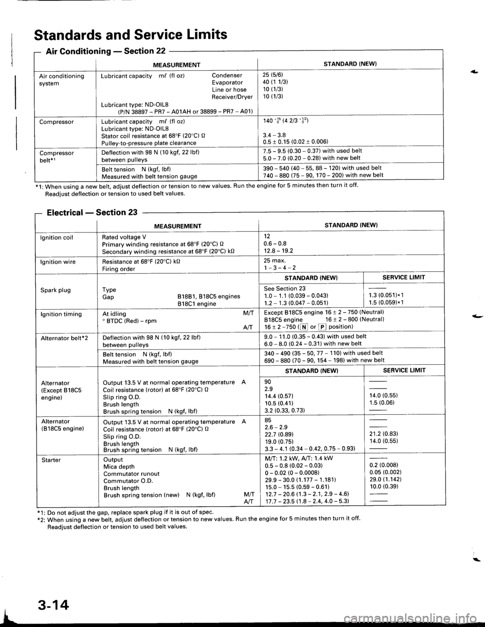
ng
MEASUREMENTSTANDARD {NEW}
Air conditioningsystemLubricant capacity m/ (fl oz) CondenserEvaporatorLine or hoseReceiver/Drver
Lubricant type: ND-OlL8(P/N 38897 - PR7 - A01AH or 38899 - PR7 - A01)
25 1516l40 (1 1/3)10 (1/3)
10 (1/3)
CompressorLubricant capacity m/ (fl oz)Lubricant type: ND-OlL8Stator coil resistance at 68'F (20"C) OPulley-to-pressure plate clearance
140'�trs 142B'�y'�l
3.4 - 3.80.5 I 0.15 (0.02 1 0.006)
Compressorbelt*rDeflection with 98 N (10 kgf. 22 lbf)between pulleys
7.5 - 9.5 (0.30 - 0.37) with used belt5.0 - 7.0 (0.20 - 0.281 with new belt
Belt tension N (kgf, lbf)Measured with belt tension gauge390 - 540 (40 - 55, 88 - 120) with used belt740 - 880 (75 - 90, 170 - 200) with new belt
*1: When using a new belt, adjust deflection or tension to new values. Run the engine for 5 minutes then turn it off.
Standards and Service Limits
Air Conditionins - Section 22
Readjust deflection or tension to used belt values.
Electrical - Section 23
f1: Do not adjust the gap, replace spark plug if it is out of spec'*2: When using a new belt. adjust deflection or tension to new values. Run the engine for 5 minutes then turn it off.
Readjust deflection or tension to used belt values.
a.
t-
MEASUREMENTSTANDARD (NEW}
lgnition coilRated voltage VPrimary winding resistance at 68"F (20'C) O
Secondary winding resistance at 68'F (20"C) k0
120.6 - 0.812.8 - 19.2
lgnition wireResistance at 68'F (20'C) k0Firinq order
25 max.1-3-4-2
Spark plugI ypeGap B18B1, 818C5 engines818C1 engine
STANDABD {NEWISERVICE LIMIT
See Section 231.0 - 1.1 (0.039 - 0.04311.2 - 1.3 (0.047 - 0.051)i-= roru',t.',1.5 (0.0591* 1
lgnition timingAt idling' BTDC (Red) - rpmM/T
AIT
Except 818C5 engine 16 ! 2 -750 (Neutral)
818C5 engine 16 t 2 - 800 (Neutral)
16!2-750 t1r{ or p position)
Alternator belt*2Deflection with 98 N (10 kgf, 22 lbf)between pulleys9.0 - 1 1.0 (0.35 - 0.43) with used belt6.0 - 8.0 (0.24 - 0.31) with new belt
Belt tension N (kgf, lbflMeasured with belt tension gauge340 - 490 (35 - 50. 77 - 1'l0l with used belt
690 - 880 (70 - 90. 1 54 - 198) with new belt
Alternator(Except B18C5engine)
Output 13.5 V at normal operating temperature A
Coil resistance (rotor) at 68'F (20'C) OSlip ring O.D.Brush lengthBrush spring tension N (kgf, lbf)
STANDARD {NEW}SERVICE LIMIT
902.914.4 (0.571
10.5 (0.41)
3.2 (0.33, 0.73)
,0, to.uur1.5 (0.06)
Alternator(B l8C5 enginelOutput 13.5 V at normal operating temperature A
Coil resistance (rotor) at 68"F (20'Cl O
Slip ring O.D.Brush lengthBrush spring tension N (kgf, lbf)
852.6 - 2.922.7 rc.89119.0 (0.75)
3.3 - 4.1 (0.34 - 0.42, 0.75 - 0.93)
',to.tg14.0 (0.55)
StarterOutputMica depthCommutator runoutCommutator O.D.Brush lengthBrush spring tension (new) N (kgf, lbf)M/TA/T
Mll:1.2 kW, A"rT: 1.4 kW0.5 - 0.8 (0.02 - 0.03)0 - 0.02 (0 - 0.0008)29.9 - 30.0 (.177 - 1.18111s.0 - 15.5 (0.59 - 0.61)12.7 - 20.6 (.3 - 2.1, 2.9 - 4.6)17 .7 - 23.5 11.8 - 2.4, 4.0 - 5.3)
0.2 (0.008)
0.05 (0.002)
29.0 (1.1421
10.0 (0.39)
3-14