1998 HONDA INTEGRA oil cap
[x] Cancel search: oil capPage 162 of 1681

I
i
Pistons
Installation (cont'dl
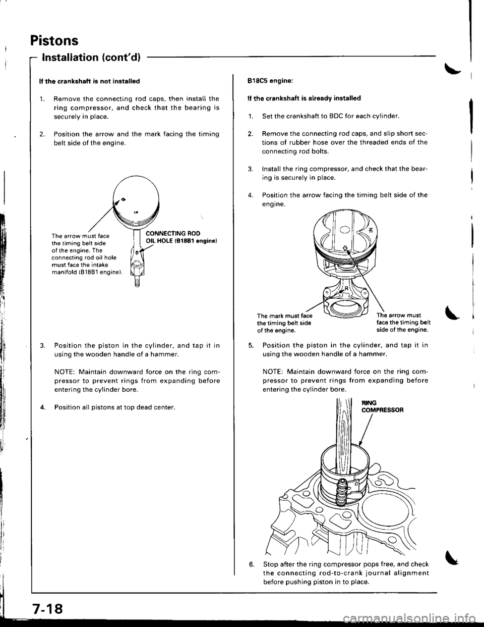
ll the crankshaft is not installed
1. Remove the connecting rod caps, then install the
ring compressor. and check that the bearing is
securely in place.
2. Position the arrow and the mark facing the timing
belt side of the engine.
ItIl
Iti
tfll|lflI[lrB
[:
i"lrt
i'
ff
ll,
illi
llillr
il
The arrow must facethe timing belt sideof the engine. Theconnecting rod oil holemust face the intakemanilold (8188'l engine).
Position the piston in the cylinder, and tap it in
using the wooden handle of a hammer.
NOTE: Maintain downward force on the ring com-
pressor to prevent rings from expanding before
entering the cylinder bore.
Position all pistons at top dead center.
7-18
818C5 engine:
ll the crankshaft is already installed
1. Set the crankshaft to BDC for each cylinder.
2. Remove the connecting rod caps, and slip short sec-
tions of rubber hose over the threaded ends of the
connecting rod bolts.
3. Install the ring compressor, and check that the bear-
ing is securely in place.
4. Position the arrow facing the timing belt side of the
eng ine.
The mark must facethe timing belt sideof the engine.
The arrow mustlace the timing beltside of the engine.
Position the piston in the cylinder, and tap it in
using the wooden handle of a hammer.
NOTE: Maintain downward iorce on the ring com-
pressor to prevent rings from expanding before
entering the cylinder bo.e.
6. Stop after the ring compressor pops free, and check
the connecting rod-to-crank journal alignment
before pushing piston in to place.
Page 163 of 1681

I
7.
8.
9.
Check the sonnecting rod bearing clearance withplastigage (see page 7-9).
Apply engine oil to the bolt threads, then install the
rod caps with bearings.
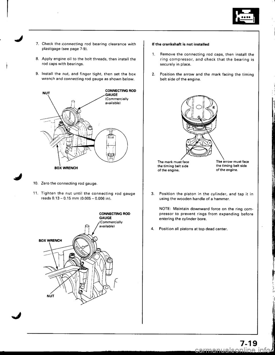
Install the nut, and finger tight, then set the boxwrench and connecting rod gauge as shown below.
CONNCCNNG RODGAUGE{Commerciallyavailable)
10.
WRENCH
Zero the connecting rod gauge.
Tighten the nut until the connecting rod gauge
reads 0.13 - 0.15 mm (0.005 - 0.006 in).
CONNECNNG HOOGAUGE
1t.
ll the crankshaft is not installed
1. Remove the connecting rod caps, then install the
ring compressor, and check that the bearing is
securely in place.
2. Position the arrow and the mark facing the timing
belt side ot the engine.
The mark must facethe timing belt sideof the engine.
Tb6 arrow must tac6th€ timing belt sideof the engine.
Position the piston in the cylinder, and tap it in
using the wooden handle of a hammer.
NOTE: Maintain downward force on the ring com-pressor to prevent rings from expanding before
entering the cylinder bore.
Position all pistons at top dead center.
Page 170 of 1681

t'
Crankshaft
lnstallation
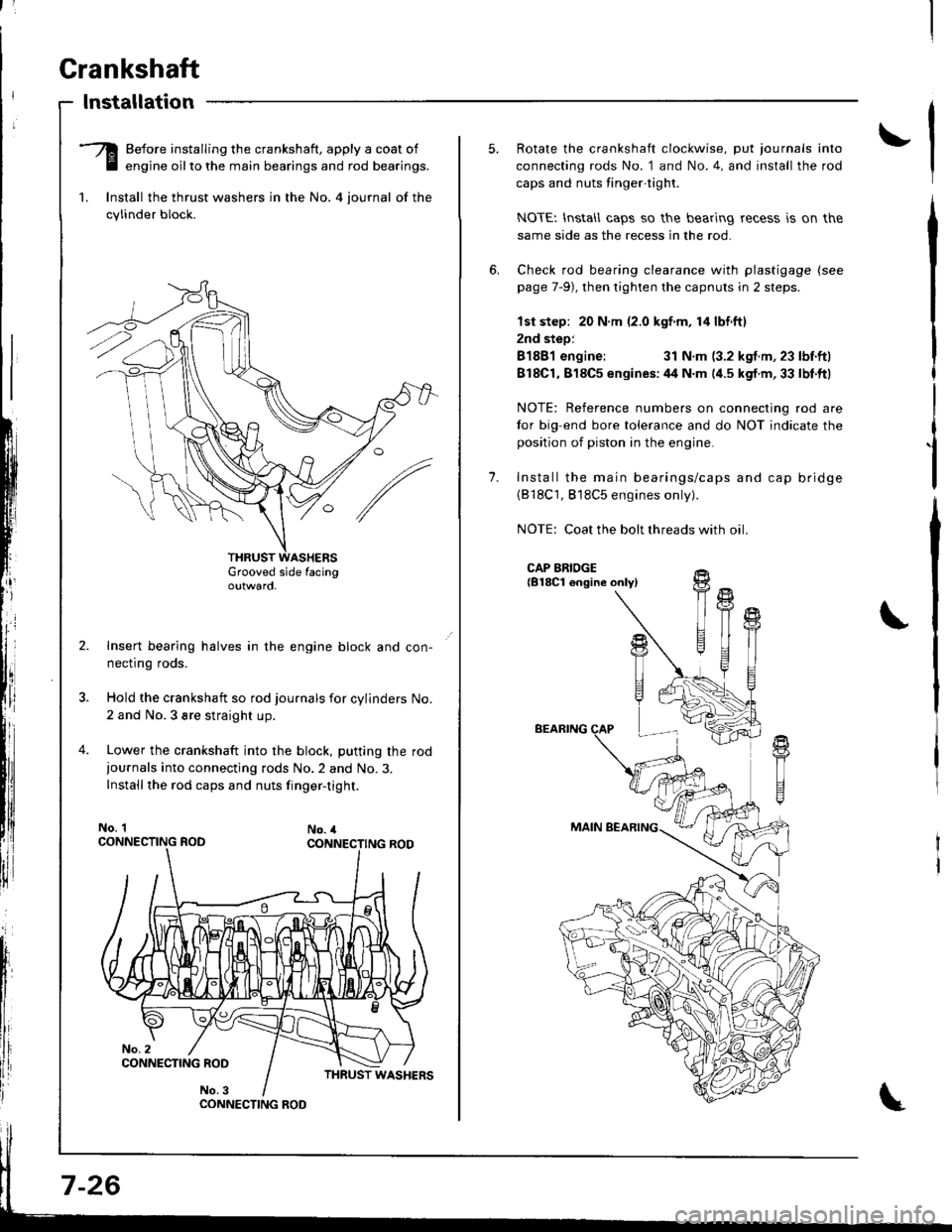
-Q Before installing the crankshaft, apply a coat of
E engine oilto the main bearings and rod bearings.
1. lnstall the thrust washers in the No. 4 iournal of the
cylinder block.
Grooved side facingoutwaro,
Insert bearing halves in the engine block and con-
necflng roos.
Hold the crankshaft so rod journals for cylinders No.
2 and No.3 sre straight up.
Lower the crankshaft into the block, putting the rod
iournals into connecting rods No.2 and No.3.
Installthe rod caps and nuts finger-tight.
No. 1No. 4
CONNECTING ROO
7-26
1.
Rotate the crankshaft clockwise, put journals into
connecting rods No. 1 and No.4, and install the rod
caps and nuts tinger-tight.
NOTEI lnstall caps so the bearing recess is on the
same side as the recess in the rod.
Check rod bearing clearance with plastigage (see
page 7-9), then tighten the capnuts in 2 steps.
lst step: 20 N.m (2.0 kgf m, 14 lbf.ftl
2nd step:
81881 engine:31 N.m (3.2 kgf.m, 23 lbf.ftl
818C1,818C5 enqines:44 N.m (4.5 kgf.m,33 lbt.ftl
NOTE: Reference numbers on connecting rod are
tor big-end bore tolerance and do NOT indicate the
position of piston in the engine.
Install the main bearings/caps and cap bridge(818C1, 818C5 engines only).
NOTE: Coat the bolt threads with oil
CAP BRIDGE{B18Cl engine onlyl
BEARING
MAIN BEARING
fi
U
t{
T
!+
T1
Page 171 of 1681

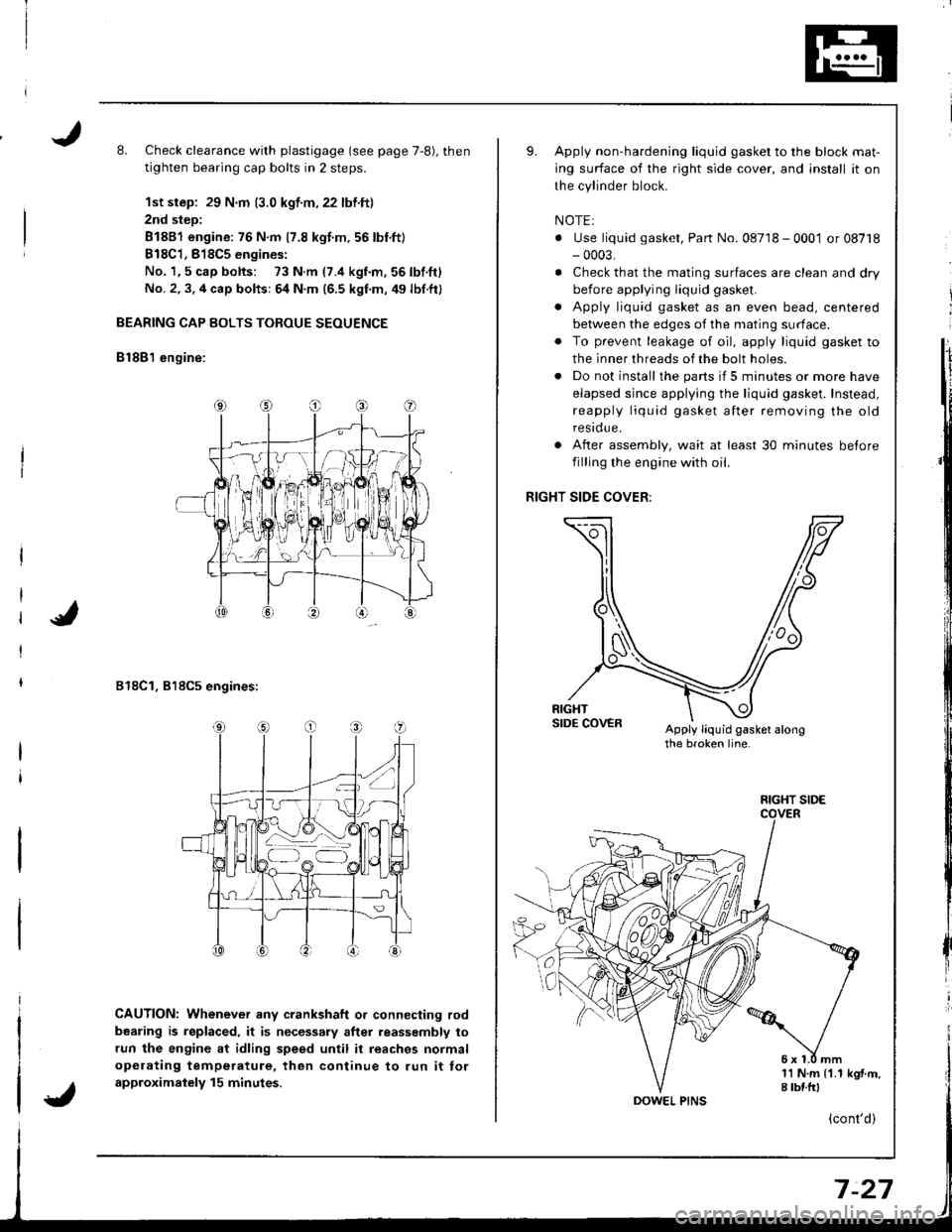
L Check clearance with plastigage (see page 7,8), then
tighten bearing cap bolts in 2 steps.
1st step: 29 N.m (3.0 kgf.m,22 lbf.ft)
2nd step:
81881 engine: 76 N.m 17.8 kgt.m.56 lbnft)
B18C1,818C5 engines:
No. 1,5 cap bolts: 73 N.m (7.4 kgnm,56lbf.ft)
No. 2, 3. 4 cap bolts: 64 N.m (6.5 kgf.m, 49 lbf.ft)
BEARING CAP BOLTS TOROUE SEOUENCE
B lSB'l engine:
818C1, 818C5 engines:
CAUTION: Whenever any crankshaft o. connecting rod
bearing is replaced, it is necessary after reassembly to
run the engine at idling speed until it reaches normal
opelating temperature, then continue to run it tor
approximalely 15 minutes.
Apply non-hardening liquid gasket to the block mat-
ing surface of the right side cover, and install it on
the cylinder block.
NOTEI
. Use liquid gasket, Part No. 08718 - 0001 or 08718- 0003,
. Check that the mating surfaces are clean and dry
before applying liquid gasket.
. Apply liquid gasket as an even bead, centered
between the edges of the mating surface.
. To prevent leakage of oil, apply liquid gasket to
the inner threads of the bolt holes.
. Do not install the parts if 5 minutes or more have
elapsed since applying the liquid gasket. Instead,
reapply liquid gasket after removing the old
residue.
After assembly, wait at least 30 minutes betore
filling the engine with oil.
RIGHT SIDE COVER:
Apply liquid gasket alongthe broken line.
o
a
1l N.m {1.1 kgf.m,I tbf.frl
FIGHT SIDE
(cont'd)
Page 179 of 1681

Inspection
Park the vehicle on level ground, and turn ofl the
engine. Allow the oil a few minutes to drain back
into the oil pan so the dipstick will show the actual
tevet,
Make certain that the oil level indicated on the dip-
stick is between the upper and lower marks.
lf the level has dropped close to the lower mark,
add oil until it reaches the upper mark.
CAUTION: Insert the dipstick caretully to avoid
bending it.
Engine Oil
t'
Replacement
CAUTION: Remove the drain plug carefully while the
engine is hot; the hot oil may cause scalding.
'1. Warm up the engine.
2. Drcin the engine oil.
\
tl
tl
tl
Lii
t'l
lr
ii
I
iliIItl
J
DRAIN PLUG44 N.m (4.5 kgl.m,33 lbl.tt)
WASHERReplace.
3. Reinstallthe drain plug with a new washer, and refill
with the recommended oil.
CAUTION: Do not overtighten the drain plug.
NOTE: Under normal conditions, the oil filter should bereplaced at every other oil change. Under severe condi-
tions, the oil filter should be replaced at each oil change.
\
-Ff
_ ,€- @
'@
oE
RequirementAPI Service Grader Use "Energy
Consetuing " SJ or "Energy
Conserving ll" SH grade oil SAE
5W 30 preterred.
You can also use an oil {rom a con
ta,ner that bears the API CERTIFI
CATION MARK.
CapacityB188 l engine:
3.5 | 13.7 US qt,3.1 lmp qt)
at oil change.
3.8 | (4.0 US qt,3.3 lmp qt)
at change, including filter.
4.6 | (4.9 US qt,4.0 lmp qt)
after engine overhaul-
Bl8C1, Bl8C5 engines:
3.7 f (3.9 US qt,3.3 lmp qt)
at oil change.
4.0 ( (4.2 US qt,3.5 lmp qt)
at change, including filter.
4.8 | (5.1 US qt,4.2 lmp qt)
after engine overhaul.
Cha ngeEvery 7,500 miles (12,000 km) or 12
months {Normal conditionsi.
Every 3,750 miles 16,000 km) or 6
months (Severe conditions).
8-6
Page 202 of 1681

Cap Testing
1.Remove the radiator cap, wet its seal with engine
coolant, then install it on the pressure tester.
Apply a pressure of:
93 123 kPa(0.95 1.25 kgf/cm', 13.5 17.8 psi)
Check for a drop in pressure.
2.
3.
AOAPTOR(for small cap)
PRESSURE TESTER
Radiator
Pressure Testing
1. Wait until the engine is cool, then carefully remove
the radiator cap and fill the radiator with engine
coolant to the top ot the filler neck.
2. Attach the pressure tester to the radiator and apply
a pressure of:
93 123 kPa(O.95- 1.25 kgf/cmr, 13.5-'17.8 psi)
3. Inspect lor engine coolant leaks and a drop inpressure.
4. Remove the tester and reinstall the radiator cap.
NOTE:
a Check for engine oil in the engine coolant and/orcoolant in the engine oil.a Check for ATF in the engine coolant and/orcoolant in the ATF {A/T}.
\
PRESSURE TESTES
AOAPTOR{for small cap)
Page 372 of 1681

aintenance
Transmission Oil
NOTE: Check the transmission oil with the engine OFF
and the vehicle on level ground.
1. Remove the oil filler plug, then check the level and
condition of the oil.
OIL FILLER PLUG44 N.m {4.5 kgf.m,Proper Level33 tbf.ftl
The oil level must be up to the filler hole. lf it is
below the hole, add oil until it runs out, then rein-
stall the oil filler plug.
lf the transmission oil is dirty, remove the drainplug and drain the oil.
Reinstall the drain plug with a new washer, and
refillthe transmission oilto the proper tevet.
NOTE: The drain plug washer should be replaced at
every oil change.
Oil Capacity
2.2 | i.2.3 US.qr,1.9 lmp.qtl at oil ch.nge.
2.3 t l2.1US.qt,2.O lmp.qtl at ovorhaul.
Always use genuine Honda manual transmission
fluid (MTF). Using motor oil can causa€tiffer shift-
ing because it does not contain the proper addi-
Back-up Light Switch
Replacement
NOTE: To check the back-up light switch. see section 23.
1. Disconnect the connector, then remove the back-up
light switch connector from the connector clamp.
l.m {2.5 kgf.m, 18lbf.ft) Replace.
Remove the back-up light switch.
Install the new washer and the back-up light switch.
Check the transmission oil level.
!ves.
OIL FILLER PLUG
DRAIN PLUG39 N.m {4.0 kg{.m,29 rbf.ftlReplace.
5. Reinstall the oil filler plug with a new washer,
Replace.
EACK.UP LIGHT SWITCH25 N.m {2.5 kgf.m, 18 lbf.ft)
13.3
Page 418 of 1681

Automatic Transmission
Special Tools ................ '14-2
Descraption .................... 14-3
Clutches ............ ...... 14-6
Power Flow ..,........... 14-8
Electronic Control System ..................... 1 4-1 8
Hydraulic Control ...... 14-23
Hydraulic Flow .........- 14-28
Lock-up System ........ 14-38
Electrical System
Component Location -................................ 1 4-45
Circuit Diagram ............. 14-46
TCM Terminal Voltage/
Measuring Conditions ......,.................... 1 4-48
Troubleshooting Procedures .. . ... ........ ...... ... 14-50
Symptom-to-Component Chart
Electrical System ...... 14-54
Electrical Troubleshooting
Troubleshooting Flowcharts .......... ... ...,.. 14-56
Lock-up Control Solenoid Valve A/B Assembly
Test .................. ...... 14-A7
Replacement ............. 14-a7
Shilt Control Solenoid Valve A/B Assembly
Test .................. ...... '14-88
Replacement .,..,........ 14-88
lvlainshaf t/Countershaft Speed Sensors
Replacement ....-......,. 14-89
Transmission Control Module (TCM)
Replacement ............. 14-89
Hydraulic System
Symptom-to-Component Chart
Hydraulic System ...... 14-90
Road Test ,................... 14-94
Stall Speed
Test .................. ...... 14-97
Fluid Level
Checking/Changing .... 14-98
Pressure Testing ........... 14-99
Transmission
Transmission
Removal ............. ...... 14-10�4
lllustrated lndex
Transmission/Right Side Cover ............... 1 4-1 08
Transmission Housin9 ................,..,....... 1 4-1'1 O
Torque Converter Housing/ValveBody .................. .. 14-112
Right Side Cover
Removal ............. ...... 14-114
Transmission Housing
Removal ............. ...... 14-1 l6
Torque Converter Housing/Valve Body
Removal ............. ...... l4-1 18
Valve Caps
Description ...........-... 14-120
Valve Body
Repair ................ ...... 14-12'l
Valve
Assembly
ATF Pump
Inspeclton
Main Valve Body
Disassembly/lnspection/Reassembly
Regulator Valve Body
Disassembly/lnspection/Reassembly
Lock-up Valve Body
Disassembly/lnspection/Reassembly
Secondary Valve Body
Disassembly/lnspection/Reassembly
Servo Body
....... 14-124
....... 14-126
....... 14-127
....... 14 124
Disassembly/lnspection/Reassembly .......
1st-hold Accumulator/Right Side Cover
Disassembly/lnspection/Reassembly .......
Mainsha{t
14-130
14-132
Disassembly/lnspection/Reassembly ....... 14-133
Inspection ................. 14-134
Countershaft
Disassembly/lnspection/Reassembly,..,.., l4-136
Disassembly/Reassembly ..,...,..,.........,,.. 1 4-1 37
Inspection ......,...,..,... 14-138
One-way Clutch
Disassembly/lnspection/Reassembly ....,.. 14-141
Sub-shaft
Disassembly/lnspection/Reassembly ...,,..'14-142
Disassembly/Reassembly ....................... 1 4- l 43
Sub-shaft Bearings
Replacement ,..,,.,,..,.. 14-144
Clutch
lllustrated Index ................................... I 4-1 45
Disassembly ............. 14-144
Reassembly .............. 14-150
Torque Converter Housing Bearings
Mainshaft Bearing/Oil Seal
Replacement ......... 14-154
Countershaft Bearing Replacement ......... 1 4- 1 55
Transmission Housing Bearings
Mainshaft/Countershaft BearingReplacement ......,.. 14-'156
Sub-shaft Bearing Replacement .,............ 1 4-1 57
Reverse ldler Gear
Installation .........-..... 14-158
Parking Brake Stop
Inspection/Adjustment .......................... 1 4-1 58
Transmission
Reassembly .............. 14-160
Torque Converler/Drive Plate ..............,.,,.,, 1 4-1 67
Transmission
Installation ............... 14-168
Cooler Flushing ......... 14-172
ATF Cooler Hoses
Connection ,..,,,....,,.,, '14-'174
*shift cable
Removal/lnstallation . . .. .... ... .... ... .... .. . ... .. 14-'l75
Adjustment ,..,...,,,,.,, 14-'116*Shilt lever
Disassembly/Reassembly ....................... 1 4-'17 7'Shift Indicator Panel
Adjustment .............. 14-178
\l
)g