Page 1235 of 1681
Dash Lights Brightness Control
Circuit Diagram
UNDER-HOOO FUSgRELAY 8OXUNDEN.DASHFUSE/RELAYEOXtX"f -.------^-;^*;;ilLrcrTswrc.
ffiwHT-lf-FEDGaN
, &TGEAN POSITION INOICATOROIMMING CIFCUIT.ATTGEAB POSITION CONSOLE LIGHT
. CRUISE COI,{TROL DIMMING CIRCUIT.CRUISE CONTHOT MAIN SWITCH LIGHT.GAUGE LIGHTS.HAZAFDWABN NG SWITCH LIGHT. HEATER CONTROL PANEL LIGHTS. REAR WINDOW DEFOGGER SWITCH LIGHT
23-178
Page 1247 of 1681
Brake
Brake
Lights
Switch TestHigh Mount Brake Light Replacement
\
t
2.
t.
3.
lf the brake lights do not go on. check the No. 52
{20 A) fuse in the under-hood fuse/relay box, and
the brake light bulbs in the taillight assembly and
high mount brake light.
lf the fuse and bulbs are OK, disconnect the 2P or
4P connector from the brake switch.
Without c.uisecontrol syst€mWilh cruisecontrol sYstem
Check for continuity between the B and C terminals.
There should be continuity with the brake pedal
pusneo.
a lf there is no continuity, replace the switch or ad-just pedal height (see section '19).
o It there is continuity, but the brake lights do not
go on, inspect for:
Poor ground (G5O3)
An open in the wire
AB
FS-A
lt--Ltl, t!,Z-\CD
-/Branl-ltl
tLatl\c
(LED typel
1. Remove the tour screws and the high mount brake
light, then disconnect the connectors.
TAILGATE SPOILER
HIGH MOUNT BRAKE LIGHT {tED TYPE}
23-190
Page 1308 of 1681
Cruise Control
)
Component LocationIndex
CRUISE LIGHT{Built into gauge assembly)Bulb Locations, page 23 122MAIN SWITCHTest, page 23-261Replacement, page 23-261SET/RESUME SWITCHTest, page 23 259Feplacement, page 23'259
BRAKE SwlTCHTest, page 23-262
CLUICH SWITCH IM/T)Test, page 23 262
cRutsEA/T GEAR POSITIONswtTcHTest, page 23-144,263Input Test, page 23 257
(cont'd)
23-253
Page 1309 of 1681
Cruise Control
Component Location Index (cont'd)
ACTUATOR ASSEMBLYTest, page 23-264Cable adjustment, page 23-264
23-254
Page 1311 of 1681

t
t;
i'l
I
dil
Gruise Gontrol
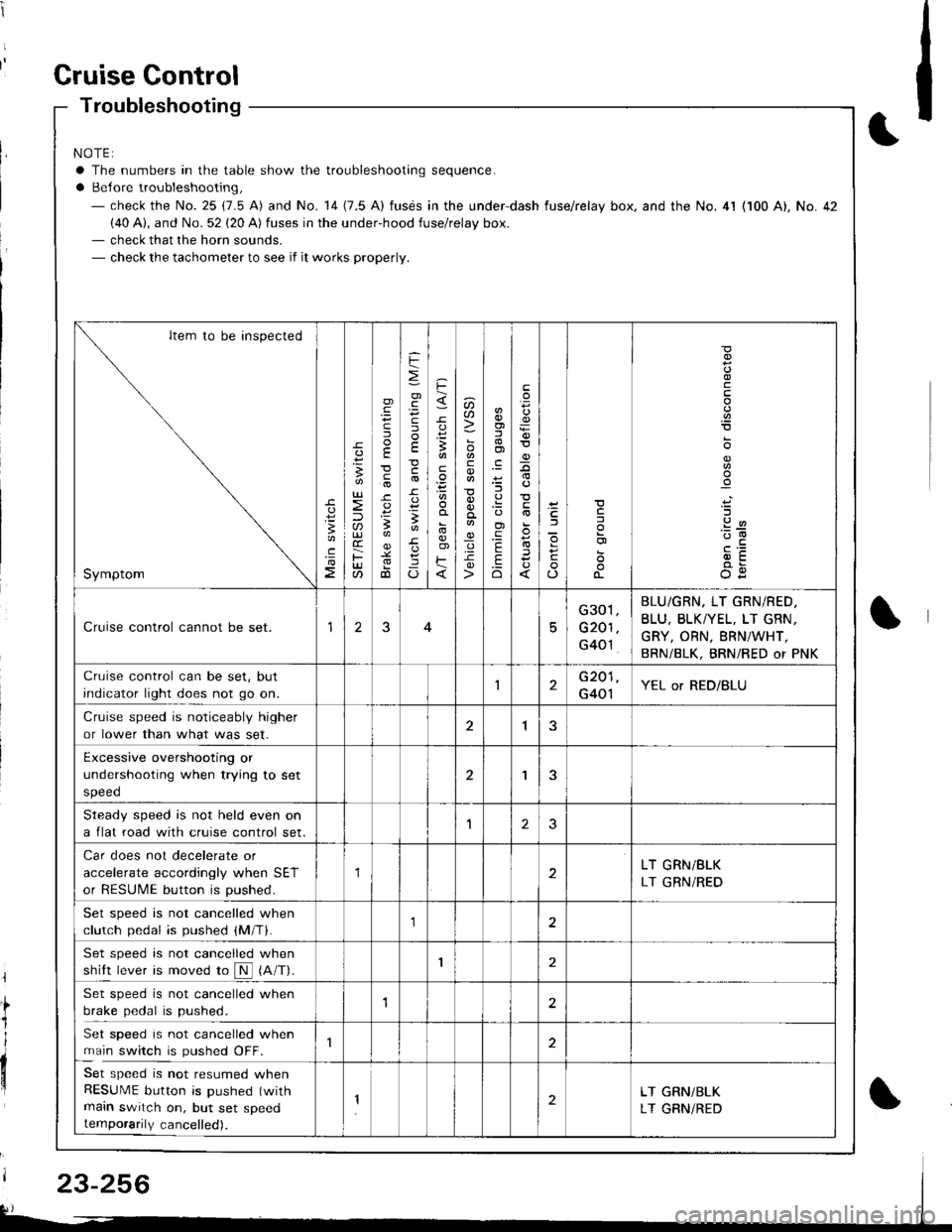
Troubleshooting
NOTE:
a The numbers in the table show the troubleshooting sequence.
a Belore troubleshooting,- check the No. 25 (7.5 A) and No. 14 (7.5 A) fusds in the under-dash fuse/relay box. and the No. 4l (100 A), No. 42(40 A), and No. 52 (20 A) fuses in the under-hood fuse/relay box.- check that the horn sounds.- check the tachometer to see if it works properly.
Item to be inspected
Symptom
c
:3
UJ
lU)(r
F(t
)
E
c
.
F
=
.g
E
-c
!-
Io
F
3
E
o)F
u)U'
co
_q.9-c
o)f,
ol
;l
E
.Eo
F
E
_9
)a
o
o-
o
c
.2
'::-c
OE
Cruise control cannot be set.15
G301
G201
G40't
BLU/GRN, LT GRN/RED.
BLU, BLKTYEL, LT GRN.
GRY, ORN, BRNiWHT,
BRN/BLK, BRNi RED or PNK
Cruise control can be set, but
indicator light does not go on.1G201
G401YEL or RED/BLU
Cruise speed is noticeably higher
or lower than what was set.1
Excessive overshooting or
undershooting when trying to set
speed
'I
Steadv soeed is not held even on
a flat road with cruise control set.1J
Car does not decelerate or
accelerate accordingly when SET
or RESUME button is pushed.
1LT GRN/BLK
LT GRN/RED
Set speed is not cancelled when
clutch pedal is pushed (M/T).1
Set speed is not cancelled when
shift lever is moved ro N (A/T).I
Set speed is not cancelled when
brake pedal is pushed.12
Set speed is not cancelled when
main switch is pushed OFF.
Set speed is not resumed whenRESUME button is pushed (with
main switch on, but set speedtemporarily cancelled).
2LT GRN/BLK
LT GRNiRED
23-256
Page 1312 of 1681
ControlInputTestUnit
'LRemove the dashboard lower cover and knee bolster(see page 23-71).
Disconnect the 14P connector from the control unit.
Inspect the connector and socket terminals to be
sure they are all making good contact.
a lf the terminals are bent, loose or corroded, repair
them as necessary, and recheck the system.a lf the terminals look OK, make the following input tests at the connector.
It any test indicates a problem, find and cor-
rect the cause, then recheck the system.
lf allthe input tests prove OK, the control unit
must be faulty; replace it.
3.
CRUISE CONTROL UNIT
View from w re s ce
(cont'd)
LT GRN/RED
14P CONNECTOR
)
23-257
Page 1313 of 1681

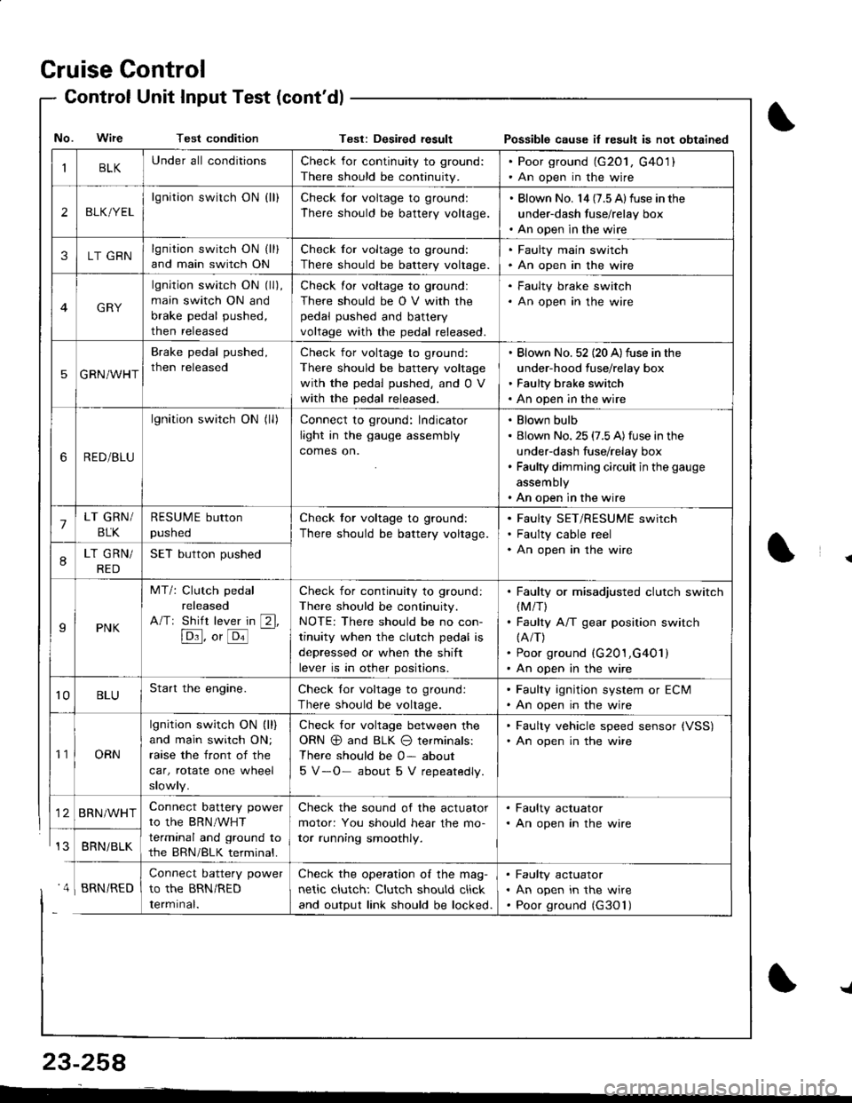
Cruise Control
- Control Unit InputTest(cont'dl
IBLKUnder all conditionsCheck for continuity to ground:
There should be continuity.
. Poor ground (G20l, G401). An open in the wire
2BLK/YEL
lgnition switch ON {ll}Check for voltage to ground:
There should be battery voltage.
. Blown No. l4 (7.5 Alfuse in the
under-dash fuse/relay box. An open in the wire
3LT GRNlgnition switch ON (ll)
and main switch ON
Check for voltage to ground:
There should be battery voltage.
. Faulty main swjtch. An open in the wire
GRY
lgnition switch ON (ll),
main switch ON and
brake pedal pushed,
then released
Check for voltage to ground:
There should be O V with the
pedal pushed and battery
voltage with the pedal released.
. Faulty brake switch. An open in the wire
5GRN/WHT
Brake pedal pushed,
then released
Check for voltage to ground:
There should be battery voltage
with the pedal pushed, and 0 V
with the pedal released.
Blown No. 52 (20 A)fuse in the
under-hood fuse/relay box
Faulty brake switch
An open in the wire
6RED/BLU
lgnition switch ON (ll)Connect to ground: lndicator
light in the gauge assembly
comes on.
Blown bulb
Blown No. 25 (7.5 A)fuse in the
under-dash fuse/relay box
Faulty dimming circuit in the gauge
assembly
An open in the wire
7LT GRN/
BLK
RESUME button
pushed
Check tor voltage to ground:
There should be battery voltage.
Faulty SET/RESUME switch
Faulty cable reel
An open in the wire8LT GRN/
RED
SET button pushed
IPNK
MT/: Clutch pedal
released
A/Tr Shift lever in [2l,
[Dl]. o, [o'l
-
Check for continuity to ground:
There should be continuity.
NOTE: There should be no con-
tinuity when the clutch pedal is
depressed or when the shift
lever is in other positions.
Faulty or misadjusted clutch switch(M/T)
Faulty A/T gear position switch(A/T)
Poor ground (G201,G401)
An open in the wire
't0BLUStart the engine.Check lor voltage to ground:
There should be voltage.
. Faulty ignition system or ECM. An open in the wire
't1ORN
lgnition switch ON (ll)
and main switch ON;
raase the front of the
car, rotate one wheel
slowly.
Check for voltage between the
ORN @ and BLK O terminals:
There should be 0- about
5 V-O- about 5 V repeatedly.
. Faulty vehicle speed sensor {VSS). An open in the wire
BRN/WHTConnect battery power
to the BRN/WHT
terminal and ground to
the BRN/BLK terminal.
Check the sound of the actuator
motor: You should hear the mo-
tor running smoothly.
. Faulty actuator. An open in the wire
BRNi BLK
Connect battery power
to the BRN/RED
Iermrnal.
Check the operation of the mag-
netic clutch: Clutch should click
and output link should be locked.
Faulty actuator
An open in the wire
Poor ground (G30'l)
No. Wire Test conditionTest: Desiled result Possible cause il lesult is not obtained
' 4 I BRN/RED
{
{
23-258
-L
Page 1318 of 1681
A/T Gear Position Switch Test
1.Remove the center console, then disconnect the 14P
connector from the switch.
Check for continuity between the terminals in each
switch position according to the table.
NOTE:
a Move the lever back and forth at each position
without touching the button, and check for con-
tinuity within the range of free play of the shitt
lever-
a lf there is no continuity within the range of free
play, adjust the installation positjon of the switch.
View lrom terrninal side
ABCDEFG
3. lf necessary. replace the switch (see section 14).
HIJKLM
A/T Goar Position Switch {For cruise control}
Terminal
'*';----_\
n
aoo
@oo
Eoo
E
tr
tr
I
J)
)
23-263