1998 HONDA INTEGRA cruise control
[x] Cancel search: cruise controlPage 1058 of 1681
J
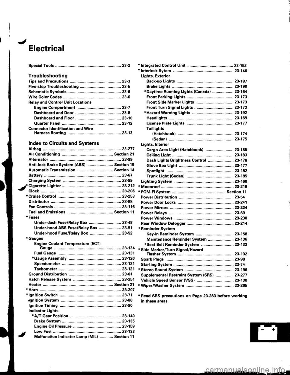
Electrical
Speciaf Toofs ..........................23-2
Troubleshooting
Tips 8nd Precautions .......................,..,.,.,.,.,......,..., 23-3
Five-step Troubleshooting ............,......,.,.,...,..,....., 23-5
Schsmatic Svmbols ...............23-6
Wire Color Code3 .. ................. 23-6
Relay and Control Unit Locations
Engine Compartment ......,.,.................,.,.,.,.,.,,,, 23-7
Dashboard and Door .........,...........,.....,.,....,.,.... 23-8
Dashboard and Floor ......................................... 23-10
Ouarter Pan€f .,,.,...,.,..,...,,,23-12
Connector ldontification and WireHarness Routing ......,.,......23-'13
Index to Circuits and Systems
Airbag
* Integrated Control Unit .....,.,.,.....23-152* Interlock Sytem .,...,.,...........,. 23.146
Lights, Exterior
Eack-up LighB ..................23.187
Brake Ligh$ ......................23-190*Daytime Running Lights (Canada) ................... 23"164
Front Parking Lights .......................................... 23-173
Front Side Marker Lights .................................. 23-173
Front Turn Signal Lights ..................-.......,...,.,. 23-173* Hazard Warning Lights ....................,........,....... 23-192
Headlights.....23-169
23-253 powerDistribution..................... 23-5/r
Air Conditioning.....,....... Soction 21
Alternator ..........,................... 23.99
iCigarette Lighter .........23-212
*Cruise Control
Distributor
'.'.,.'.'.,.'...,,,,.,''.'.,.',.'''.' 23.277
.............................. 23.88
................... 23-90lgnition Timing ......
Indicator Lights
Key-in Reminder System
Maintenance Reminder System*Seat Belt R€mindor System .,...........................* Side Marker/Turn Signal/HazardFlashcr Svstem .................23-192
Spark Plugs ............................23-98
Starting System .....................23-74* Stereo Sound System ...,......,..........,...,......,.,.,.,..,., 23-196
Supplemental Restraint System (SRS) ................ 23-277
Vshicle Speed Sensor (VSS) ................................. 23.130r Wiper/Washer System .........................................., 23-265
*Read SRS precautions on Psge 23-283 before working
in those areas,
23-154
23.136
23"133
Page 1065 of 1681
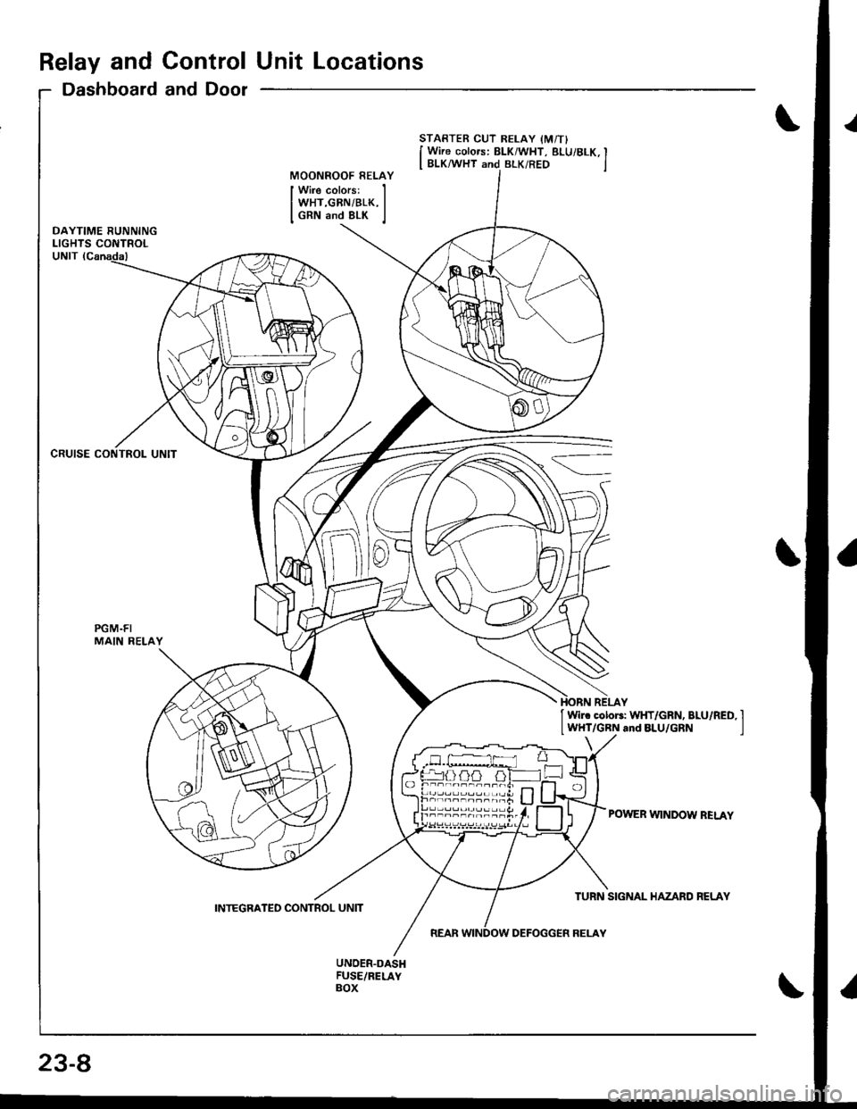
Relay and Control Unit Locations
Dashboard and Door
CRUISE CONTROL UNIT
PGM.FIMAIN RELAY
STARTER CUT RELAY IM/TI
I Wire colors: BLK/WHT, BLUi 8LK, II BLK/WHT and BLK/RED jMOONROOF RELAY
Wire colors:WHT,GBN/BLK,GRN and 8LK
I Wir. cotoF: WHT/GRN, BLU/RED, I
lWHT/GRN and BLU/GRN I
POWER WINDOW BELAY
23-8
INTEGRATED CONTROL UNIT
Page 1077 of 1681
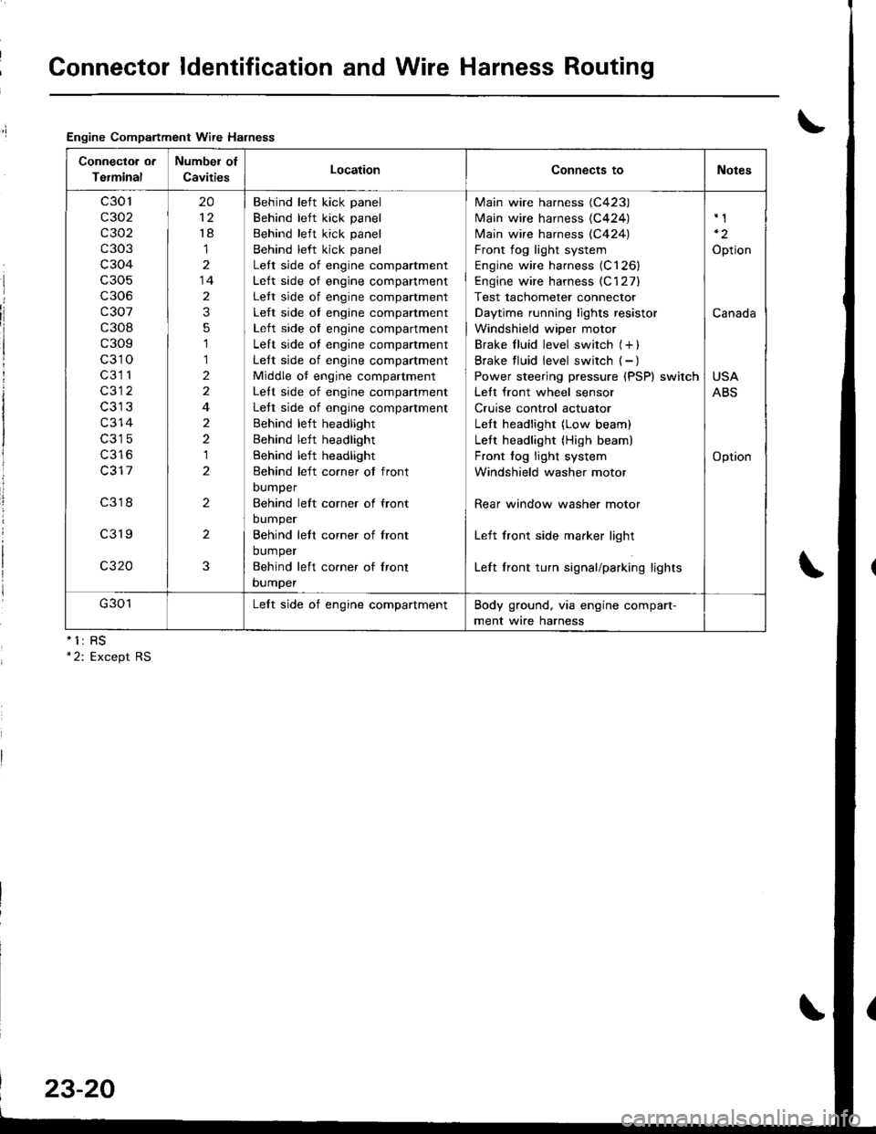
Connector ldentification and Wire Harness Routing
Engine Compartment Wire Halness
nll
Connectoa ot
Terminal
Number of
CavitiesLocationConnects toNotes
c301
c302
c 302
c303
c304
c306
c307
c308
c309
c310
c3l 1
c312
c314
c316
c317
c318
c319
c320
20
't8
1
14
2
3
5
1
1
2
2
4
2
2
1
2
2
2
3
Behind left kick panel
Behind left kick panel
Behind left kick panel
Behind left kick panel
Lett side of engine compartment
Lett side of engine companment
Lett side of engine compartment
Left side of engine compartment
Left side of engine compartment
Left side of engine compartment
Left side of engine compartment
Middle of engine compartment
Lett side of engine companment
Left side of engine compartment
Behind left headlight
Behind left headlight
Behind left headlight
Behind left corner of front
DUmper
Behind left corner ol front
bumper
Behind lett corner of front
bumper
Behind left co.ner of lront
bumper
Main wire harness (C423)
Main wire harness {C424)
N4ain wire harness (C424)
Front fog light system
Engine wire harness (C126)
Engine wire harness (C'127)
Test tachometer connector
Daytime running lights resistor
Windshield wiper motor
Brake f luid level switch (+ )
Brake f luid level switch ( - )
Power steering pressure (PSP) switch
Lett front wheel sensor
Cruise control actuator
LeIt headlight (Low beam)
Lett headlight {High beam)
Front fog light system
Windshield washer motor
Rear window washer motor
Left front side marker light
Left front turn signal/parking lights
Option
Canada
USA
ABS
Option
G301Lelt side of engine compartmentBody ground, via engine compart-
ment wire harness
23-20
Page 1083 of 1681
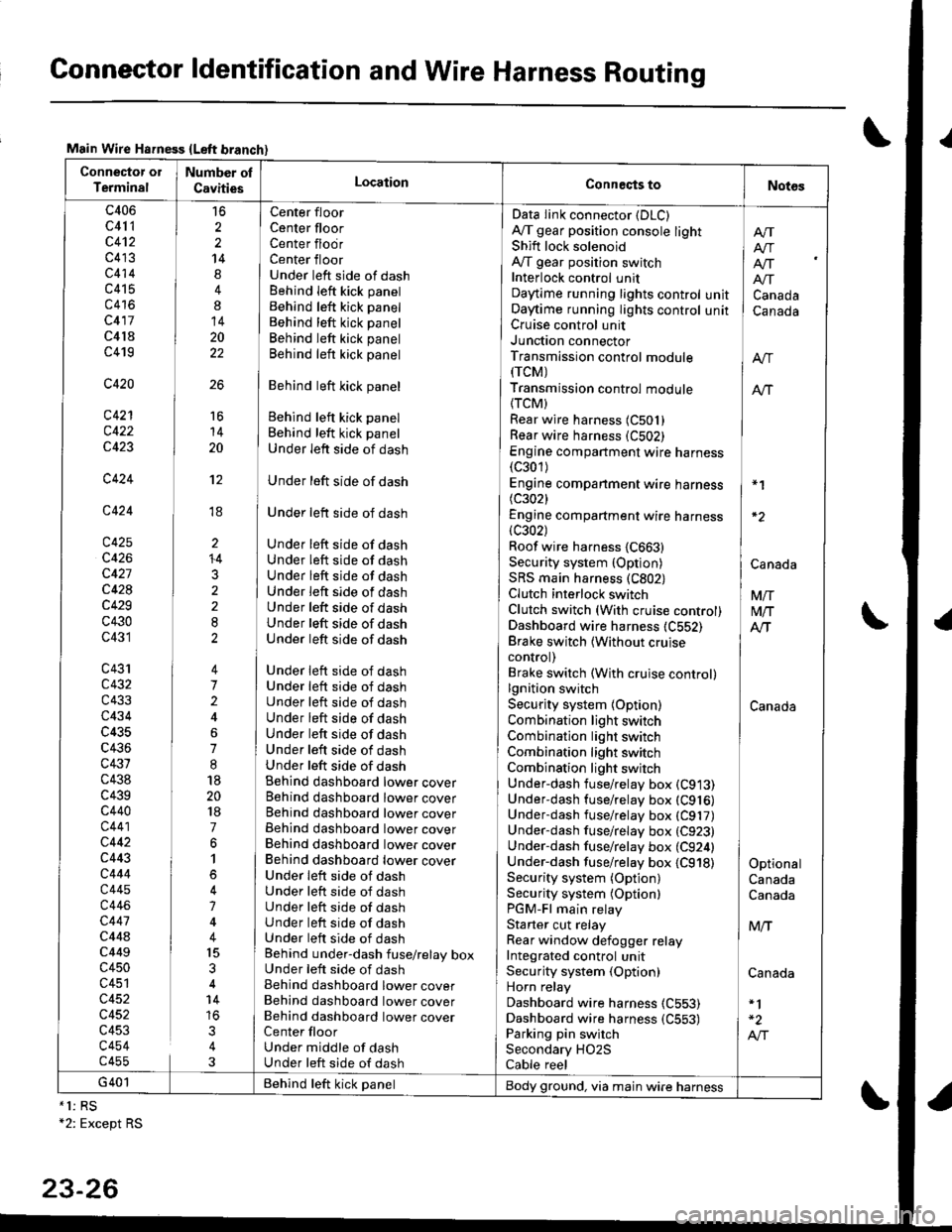
Connector ldentification and Wire Harness Routing
Main Wire Hsfness {Left branch}
Connector ol
TerminalNumber ol
CavitiesLocationConneqts toNot6s
c406
c41 1
c4't2
c413
c414
c415
c416
c417
c4l8
c419
c420
c421
c422
c423
c424
c424
c425
c426
c427
c428
c429
c430
c431
c43'rc432
c433
c434
c435
c436
c431
c438
c439c440
c441
c442
c443
c444
c445
c446
c447
c44ac449
c450
c451
c452
c452
c453
c454c455
16
2
2
14
4
8
14
20
22
26
Center floor
Center floorCenter flodrCenter floorUnder left side of dashBehind Ieft kick panel
Behind left kick panel
Behind left kick panel
Behind left kick panel
Behind left kick panel
Behind left kick panel
Behind left kick panel
Behind left kick panel
Under left side of dash
Under left side of dash
Under left side of dash
Under left side of dashUnder left side of dashUnder left side of dashUnder left side of dashUnder left side of dashUnder left side of dashUnder left side of dash
Under left side of dashUnder left side of dashUnder left side of dashUnder left side of dashUnder left side of dashUnder left side of dashUnder left side of dashBehind dashboard lower coverBehind dashboard lower coverBehind dashboard lower coverBehind dashboard lower coverBehind dashboard lower coverBehind dashboard lower coverUnder leit side of dashUnder left side of dashUnder left side of dashUnder left side of dashUnder left side of dashBehind under-dash fuse/relay boxUnder left side of dashBehind dashboard lower coverBehind dashboard lower coverBehind dashboard lower coverCenter floorUnder middle of dashUnder left side of dash
Data Iink connector (DLC)
A,/T gear position console lightShift lock solenoidAy'T gear position switchInterlock control unitDaytime running lights controlOaytime running lights controlCruise control unitJunction connectorTransmission control module(rcM)
Transmission control module
{TCM)Rear wire harness (C501)
Rear wire harness (C502)
Engine compartment wire harness(c301)
Engine companment wire harness I *1
(c3021 IEngine compartment wire harness(c302) lRoof wire harness {C663} |Security system {Option) | CanaAaSRS main harness (C802) |Clutch interlock switch I VnClutch switch (With cruise control) M/TDashboard wire harness (C552) AlTBrake switch lwithout cruise Icontrol) |Brake switch (With cruise control)lgnition switch ISecurity system {Option) CanadaCombination light switch /Combination light switch ICombination light switchCombination light switchUnder-dash fuse/relay box (C913)
Under-dash fuse/relay box (C916)
Underdash fuse/relay box (C917)
Under-dash fuse/relay box (C923)
Under-dash fuse/relay box (C924) |Under-dash fuse/relay box {C918) I OptionalSecurity system (Option) CanadaSecurity system (Optionl CanadaPGM-Fl main relayStarter cut relay ] M,.fRear window defogger relay IIntegrated control unitSecurity system (Option) CanadaHorn relay
Dashboard wire harness (C553)
Dashboard wire harness {C553) | -2
Parking pin switch I A,"ISecondary HO2S
Cable reel
Afi
I Atr
lf[
unit ] Canadaunit I Canada
16
14
20
't2
ti
I'
li
ll
li
+4
3
G401 Behind teft kick panelBody ground, via main wire harness*1: RS+2: Except RS
23-26
Page 1089 of 1681
Connector ldentification and Wire Harness Routing
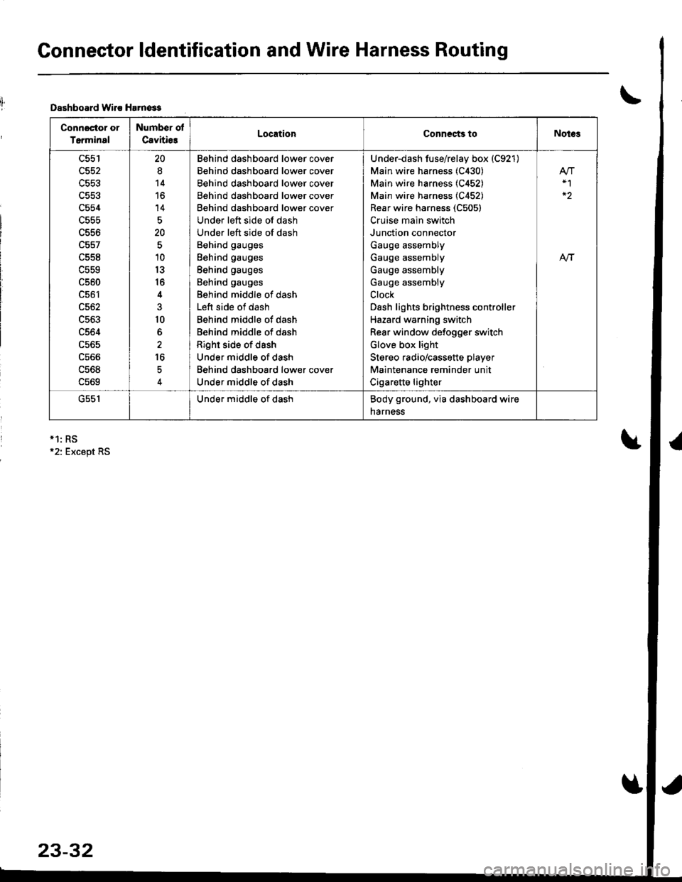
Dsshboard lvirc Harn€ss
Connoctor or
Terminal
Number ol
Cavitie3LocationCoDnects toNotes
c554
L55t'
c561
c562
c563
c564
c565
ucoo
uc06
c569
20
8
14
to
14
20
10
13
16
4
10
6
16
Behind dashboard lower cover
Behind dashboard lower cover
Behind dashboard lower cover
Behind dashboard lower cover
Behind dashboard lower cover
Under left side of dash
Under left side of dash
Behind gauges
Behind gauges
Behind gauges
Behind gauges
Behind middle of dash
Left side of dash
Behind middle of dash
Behind middle of dash
Right side of dash
Under middle of dash
Behind dashboard lower cover
Under middle of dash
Under-dash fuse/relay box (C921)
Main wire harness (C430)
Main wire harness (C452)
Main wire harness (C452)
Rear wire harness (C505)
Cruise main switch
Junction connector
Gauge assembly
Gauge assembly
Gauge assembly
Gauge assembly
Clock
Dash lights brightness controller
Hazard warning switch
Rear window defogger switch
Glove box light
Stereo radio/cassette player
Maintenance reminder unit
Cigarette lighter
At-|-
uc5 |Under middle of dashBody ground, via dashboard wire
narness
*1: RS12: Except RS
23-32
Page 1106 of 1681
T
I
1
J)
Fuso NumberWire ColorComponent{s} or Circuit(rl ftqt6cted
't210AYEUBLKTurn signal/hazard relay
15 AYEUGRNPGM-Fl main relay
GRN or REDSRS unit (VA)
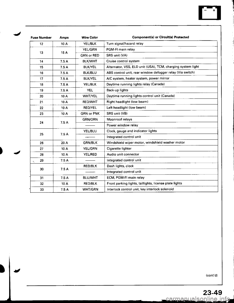
147.5 ABLK/WHTCruise control system
15BLK/YE LAlternator, VSS, ELD unit (USA), TCM, charging system light
't67.5 ABLVBLUABS control unit, rear window defogger relay (Via switch)
117.5 ABLK//ELAVC system, heater system, power marror
187.5 AYEUBLKDaytime running lights relay (Canada)
197.5 AYELEack-up lights
2010 AWHT/YELDaytime running lights control unit (Canada)
2110 ARED/WHTRight headlight (low beam)
2210 ARE D|YE LLett headlight (low beam)
2310 AGRN or PNKSRS unit (VB)
247.5 AGRN/ORNMoonroof relays
Power window relay
7.5 AYEUBLUClock, gauge and indicator lights
Integrated control unit
2620AGRN/BLKWindshield wiper motor, windshield washer motor
10AYEUGRNCigarette lighter
2810AYEUREDAudio unit connector
29Integrated control unit
30RED/BLKDash lights, clock
Integrated control unit
317.5 A8LU/WHTECM. PGM-Fl main relav
10ARE D/BLKFront parking lights, taillights, license plate lights
7.5 AWHT/GRNInterlock control unit, key interlock solenoid
23-49
Page 1154 of 1681
lgnition Control Module (lCM) Input Test
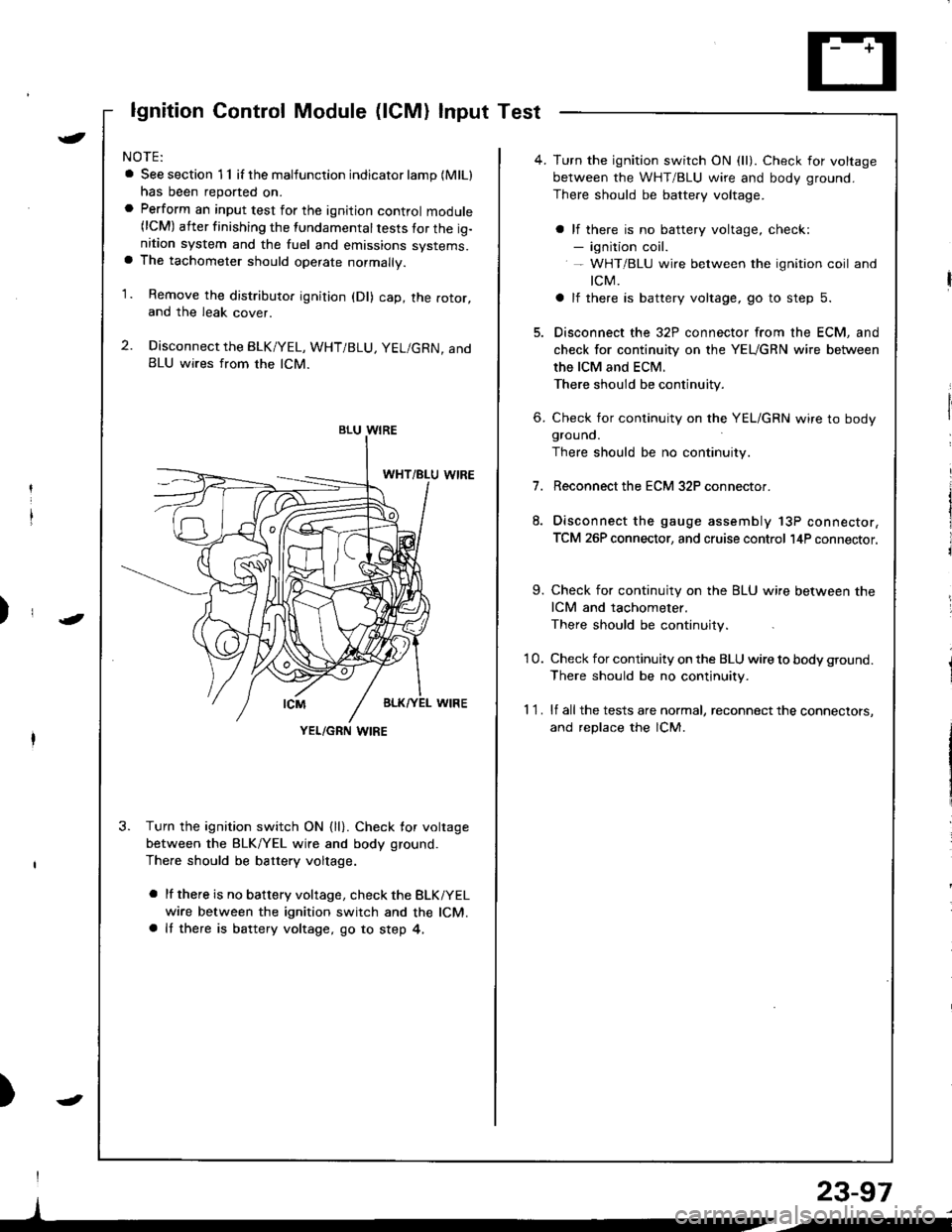
NOTE:
a See section 1 1 if the malfunction indicator lamp (MlLl
has been reported on.a Perform an input test for the ignition control module(lCM) after finishing the fundamental tests for the ig-nition system and the fuel and emissions systems.a The tachometer should operate normally.
1. Remove the distributo. ignition (Dl) cap, the rotor,and the leak cover.
2. Disconnect the BLK/YEL, WHT/BLU, YEL/GRN, andBLU wires from the lCM.
3. Turn the ignition switch ON {ll}. Check for voltage
between the BLK/YEL wire and body ground.
There should be battery voltage.
a lf there is no battery voltage, check the BLKiYEL
wire between the ignition switch and the lCM.a It there is battery voltage, go to step 4,
)
I
)
BLU WIRE
YEL/GRN I,\'IRE
4. Turn the ignition switch ON (ll). Check for voltage
between the WHT/BLU wire and body ground.
There should be battery voltage.
a lf there is no battery voltage, check:- ignition coil.- WHT/BLU wire between the ignition coil and
tcM.
a lf there is battery voltage, go to step 5.
5. Disconnect the 32P connector from the ECM, and
check for continuity on the YEUGRN wire between
the ICM and ECM.
There should be continuity.
6. Check for continuity on the YEL/GRN wire to bodygrouno.
There should be no continuity.
7.Reconnect the ECM 32P connector.
Disconnect the gauge assembly 13P connector,
TCM 26P connector, and cruise control l4P connector.
9. Check for continuity on the BLU wire between the
ICM and tachometer.
There should be continuity.
'10. Check for continuity on the BLU wire to body ground.
There should be no continuity.
1 1 . lf all the tests are normal, reconnect the connectors,
and replace the lCM.
23-97
/i
Page 1180 of 1681
UNDER.DASHFUSE/RELAY 8OX
No.l5 (7.54)
No 2s (7 5A)
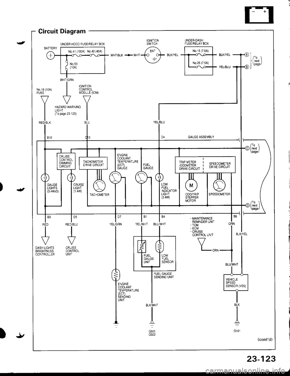
Gircuit Diagram
WHTiGRN
| $il,�4,
V
MODULE(ICM)
ru{no unrno I(To pase 23 12s)
|BtU
No.rs (10A)FUSE
V
I
GAUGE ASSEMBLY
YEUBLU
t,,
| ,,J,,
1l
|;;il'-II SPEED II SENSoBIVSS) |-t-
. MAINTENANCEREMINDER UNIT' TCM' ECM' CRUISECONTROT UNlT
f7
I-oRN
BLKMHT
I
G501
I'YEUGRN YE
ln
tl
P**,,,'
ffirxl-"
louRED/BLU
.J'-
CRUISECONTROLUNIT
BLK
I
G10l
23-123
-/
UNDEF HOOD FUSE/RELAY BOX