Page 690 of 1681

Power Steering
Gearbox
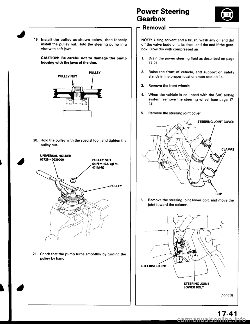
Removal
NOTE: Using solvent and a brush, wash any oil and dirt
off the valve body unit, its lines, and the end if the gear-
box. Blow dry with compressed air.
l. Drain the power steering fluid as described on page
11-21.
2. Raise the front of vehicle, and support on safety
stands in the proper locations (see section 1).
3. Remove the front wheels.
4. When the vehicle is equipped with the SBS airbag
system, remove the steering wheel (see page 17-
24t.
5. Remove the steering
6. Remove the steering joint lower bolt, and move the
ioint toward the column.
STEERING JOINTLOWER SOI-T
(cont'd)
19. Install the pulley as shown below, then loosely
install the pulley nut. Hold the steering pump in a
vise with soft jaws.
CAUTION: Be carelul not to damlge tho pump
hou3ino with ths ilws of th6 vies.
Hold the pulley with the special tool, and tighten thepu ey nut.
ioint
Va
20.
PULI.IY NUT6,1 N.m {6.5 kgt m,47 lbf,ftl
'(
Check that the pump turns smoothly by turning thepulley by hand.
.-l
21.
PULLEY
UNIVERSAL HOLDER
CLIP
17-41
Page 941 of 1681

Carpet
Beplacement
SRS wire harnesses are routed near the carpet.
CAUTION:
a All SRS wire harnesses are covered wilh yellow insu-
lation. Before you disconnect any palt of an SRS wire
harness, disconnect the airbag connectors.
a Whenever the ignition switch is ON (ll), or has been
tulned OFF fol less than three minutes, be caretul not
to bump the SRS unit; the airbags could accidentally
deploy and cause damage or inluries.
a Fof additional precautions, leter to the SRS sub-section
in section 23,
DRIVER'S AIRBAG FRONT
SRS UNIT
20-126
FOOTREST
'1. Removel
Hatchback
a Front seat (see page 20 103)
a Rear seat (see page 20-110)
a Rear shelf (see page 20'91)
a Rear trim panel (see page 20-921
a Side trim panel (see page 20 92)
a Front seat belt lower anchor (see page 20-117)
a Front and rear consoles (see page 20-'130)
. Kick panel {see page 20-91)
a Dashboard lower cover (see page 20-133)
a Opener cover (see page 20-156)
Sedan
a Front seat (see page 20 103)
. Rear seat (see page 20-1121o Rear pillar trim panel (see page 20 95)
a Center pillar lower trim (see page 20-94)
a Front seat belt lower anchor (see page 20-118)
a Front and rear consoles (see psge 20-130)
. Kick panel (see page 20'9'l)
a Dashboard lower cover (see page 20-133)
a Opener cover (see page 20-157)
2. Remove the footrest.
V i Bolt locations, 2
6xl.omm i
9.8 N.m {'l .0 kgl m,7.2 rbf.ft) )./
Page 945 of 1681
Consoles, Front and Rear
Replacement
SRS wire harnesses are routed near the front console.
CAUTION:
a AIISRS wire harnesses are covered with vellow insu-
lation. Before you disconnect any pan of an SRS wire
halness, disconnect the airbag connectors.a Whenever the ignition switch is ON {lll, o. has beenturned OFF for less than three minutes, be carefulnot
to bump the SRS unit; the airbags could accidentally
deploy and cause damage or injuries.a For additional pfecautions, reter to the SRS sub-section
in section 23.
PASSENGER'S AIRBAG
SRS UNIT
20-130
NOTEr Take care not to scratch the lront and rear con-
soles, and dashboard.
1. Remove the access cap.
CAUTION: When prying with a tlat tip screwdriver.
wrap it with protective tape to prevent damage.
ACCESS CAP
2. Remove the screws.
V : Screw locations
AV : Screw, 2 BV : Screw, 2
el
Ei-,)
*)
Page 948 of 1681

Dashboard
Component Removal/lnstallation
\J
U
uomponenl r{emoval/ Insrallarlon -
SRS wire harnesses are routed near the dashboard and
sreenng corumn.
CAUTION:
a AIISRS wire harnesses are cove.ed with yellow insu-
lation. Belore you disconnect any part of an SRS wire
hahess, disconnect the airbag connectors.
o Whenever the ignition switch is ON (ll), or has been
turned OFF fol less than three minutes, be caretul not
to bump the SRS unit; the airbags could accidentally
deploy and cause damage or inturies.
a For additional precautions, reJer to the SRS sub-section
in section 23.
FRONTPASSENGER'S AIRBAG
SRS UNIT
CAUTION: When prying with a flat tip screwdriver, wrap
it with protective tape, and apply proteclive tape around
the related parts, to prevent damage,
Instrument panel, Dashboad lower cover, Knee bolster
temovat:
1. Lower the steering column.
2. Remove the screws and detach the clips, then re-
move the instrument panel.
3. Remove the coin pocket.
4. Remove the screws and detach the clips, then re
move the dashboard lower cover.
Disconnect the connector.
A : Screwlocations,5A i Clip locations
AA: Clip, 2 B> : Clip, 2
INSTRUMENT PANEL
ii'- ' iq4'ii \Ll1
COIN POCKET
(cont'd l
20-133
Page 953 of 1681

Dashboard
Replacement Precautions
SRS wire harnesses are routed near the dashboard and
steenng column.
CAUTION:
a All SRS wire hsrnesses are covered wiih yellow insu-
lation. Before you disconnect any pan of an SRS wire
harness, disconnect the airbag conneclors.
a Whenever the ignition switch is ON (ll), or has been
tulned OFF for less than three minules, be careful not
to bump the SRS unit; the ai.bags could accidentally
deploy and cause damage or injuries.
a For additional precautions, refer lo the SRS sub-section
in section 23.
PASSENGER'S AIRBAG
Belore removing the dashboard:
1. Disconnect the battery negative cable, then discon-ne.r rhe n^.iriua.ahla
NOTEr The original radio has a coded thett protec,
tion circuit. Be sure to get the customer's code num
ber before- disconnecting the battery.- removing the No. 47 (7.5 A) fuse from the under-
hood tuse/relay box.- removing the radio.
After service, reconnect power to the radio and turn
it on. When the word "CODE" is displayed, enter
the customer's 5-digit code to restore radio
operation.
DRIVER'S AIRBAG
SRS UNIT
20-138
2.Install the short connectors (RED).
Driver's:
Remove the access panel, then disconnect the con-
nector between the cable reel and driver's airbag.
CABL€ REELCONNECTOR--_--._-_-----
Front passenger's:
Remove the glove box (see page 20-137), thendisconnect the connector between the front pas-
senger's airbag and SRS main harness.
FRONT PASSENGER'SAIRBAG CONNECTOR
SRS MAIN HARNESSCONNECTOR
ORIVER'S AIRBAG
Page 1267 of 1681
Horn
Switch Test (cont'd)
Remove the driver's airbag assembly (refer to the
SRS sub-section in section 23).
Check for continuity between the No. 2 terminal of
the cable reel sub-harness 3P connector and horn
Dositive terminal.
lf there is no continuity. replace the cable reel.
lf there is continuity, replace the horn switch.
a
a
HORN POSITIVE TERMINAL
23-210
9.
10.
11.
12.
lf all tests prove OK, reinstall the driver's airbag
assembly (re{er to the SRS sub-section in section 23).
Reconnect the driver's airbag connectors, and rein-
stall the access panel on the steering wheel.
Reconnect the front passenger's airbag connector,
and reinstall the glove box.
Connect the battery positive cable, then connect the
negative cable.
Atter installing the airbag assembly, confirm that
- the SRS indicator light should come on for about
six seconds and then go off with the ignition switch
oN 0t).- the horn sounds with the horn button pressed.
Page 1315 of 1681
Gruise Control
- Set/Resume Switch Test/Replacement {cont'dl
6, Remove the two screws and sevresume switch.
Check for continuity between the terminals in each
switch position according to the table.
lf it matche$ the table, the switch is OK. replace
the cable reel.
lf there is no continuity in one or both positions,
reolace the switch.
Not used
7.
Terminal
t*n*------l23
SET {ON)G----o
RESUME (ON}o----o
lf alltests prove OK, reinstallthe sevresume switch.
Reconnect the driver's airbag connectors, and rein'
stall the access panel on the steering wheel.
Reconnect the front passenger's airbag connector,
and reinstallthe glove box.
Connect the battery positive cable, then connect the
negative cable.
After installing the airbag assembly, confirm that
the SRS indicator light should come on for about
six seconds and then go off with the ignition switch
oN flr).
11.
12.
!a
Page 1333 of 1681

Description
I
J)
)
'\' '\, ili \.-.-1 i^\\,,; i \
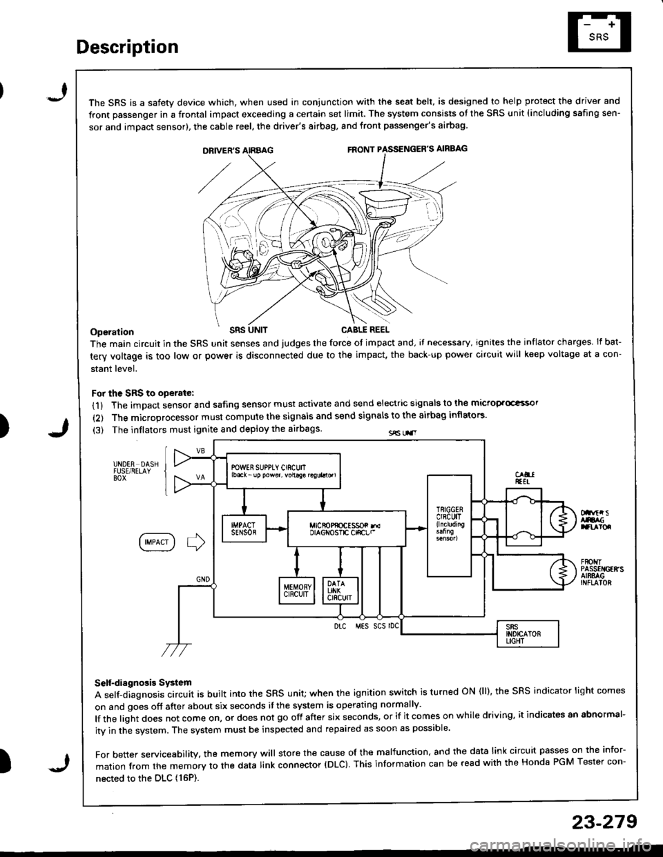
The SRS is a safetv device which, when used in coniunction with the seat belt, is designed to help protect the driver and
front passenger in a frontal impact exceeding a cenain set limit. The system consists ot the SRS unit (including safing sen-
sor and imDact sensor), the cable reel, the driver's airbag, and front passenger's airbag
Operation t'Its
The main circuit in the SRS unit senses and judges the force ot impact and, il necessary, ignites the inflator charges. If bat-
tery voltage is too low or power is disconnected due to the impact, the back-up power circuii will keep voltage at a con-
stant level.
For the SRS to operate:
(1) The impact sensor and safing sensor must activate and send electric signals to lhe mictop.Goi
{2) The microprocessor must compute the signals and send signals to the airbag inflators'
(3) The inflators must ignite and deploy the airbags sE Lr.r
UNDER DASHFUSE/RELAYBOX
Dnftr sAtacranroq
IIMPACT I ] )
F80t{TPASSEI{GEffSAIRSAGINFLAIOR
Drc MES SCS rDC
Self-diagnosis System
A self-diagnosis circuit is built into the sRs unit; when the ignition switch is turned oN (ll), the sRS indicator light comes
on and goes off after about six seconds if the system is operating normally'
lf the light does not come on, or does not go off after six seconds, or if it comes on while driving. it indicates an abnormal-
ity in the system. The system must be inspected and repaired as soon as possible'
For better servicesbility. the memory will store the cause of the malfunction, and the data link circuit passes on the infor-
mation from the memory to the data link connector (DLC). This information can be read with the Honda PGM Tester con-
nected to the DLc (16P).
23-279
J